Abstract – This paper provides a comprehensive study on how to use Profibus
fieldbus networks to support real-time industrial communications, that is, on how
...
Real-Time Fieldbus Communications Using Profibus Networks Eduardo Tovar (Member) Department of Computer Engineering, ISEP, Polytechnic Institute of Porto Rua de São Tomé, 4200 Porto, Portugal Tel.: +351.2.8340500, Fax: +351.2.8321159 e-mail:
[email protected]
Francisco Vasques (non-member) Department of Mechanical Engineering, FEUP, University of Porto Rua dos Bragas, 4099 Porto Codex, Portugal e-mail:
[email protected]
Abstract – This paper provides a comprehensive study on how to use Profibus fieldbus networks to support real-time industrial communications, that is, on how to ensure the transmission of real-time messages within a maximum bound time. Profibus is based on a simplified Timed Token (TT) protocol, which is a well-proved solution for real-time communication systems. However, Profibus differs with respect to the TT protocol, thus preventing the application of the usual TT protocol real-time analysis. In fact, real-time solutions for networks based on the TT protocol rely on the possibility of allocating specific bandwidth for the real-time traffic. This means that a minimum amount of time is always available, at each token visit, to transmit real-time messages. Conversely, with the Profibus protocol, in the worst-case, only one real-time message is processed per token visit. We propose two approaches to guarantee the real-time behaviour of the Profibus protocol: an Unconstrained Low Priority Traffic profile and a Constrained Low Priority Traffic profile. The proposed analysis will show that the first profile is a suitable approach for more responsive systems (tighter deadlines), whilst the second allows for increased non-real-time traffic throughput. Keywords – Field buses, Protocols, Real-Time Systems
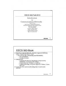
I. INTRODUCTION A recent trend in distributed process control systems is to interconnect the distributed elements by means of a multi-point broadcast network, instead of using the traditional point-topoint links. Within industrial communication systems, fieldbus networks are specially intended for the interconnection of process controllers, sensors and actuators, at the lower levels of the factory automation hierarchy (Fig. 1). These hierarchical levels have dissimilar message flows, in terms of required response times, amount of information to be transferred, required reliability and message rates (how frequently messages must be transferred) [1].
-1-
It is known that time constraints are more stringent as we go down in the automation hierarchy. In the context of this paper, we consider time constraints or deadlines as the maximum allowable time span between a message transfer request and its transmission on the bus. In fact, the total message cycle delay results from multiple factors, such as the access and queuing delays, the transmission time (frame length / transmission rate) and the protocol processing time. As we are dealing with real-time communication across a shared transmission medium, we focus our analysis on the access delay and queuing delay factors. These factors depend on the Medium Access Control (MAC) mechanism used by the fieldbus network. Planning Level Bus cycle-time >> 1000 ms
AREA CONTROLLER
Factory Level
Higher Level Networks
Bus cycle-time < 1000 ms
CNC
PC
Cell Level
HOST
Cell or Fieldbus Networks
Bus cycle-time < 100 ms
PC
Field Level
PLC
DCS
Fieldbus Networks
Bus cycle-time < 10 ms
I/O
Valve
Drive
Transmitter
Field Device
Figure 1 - Communication Networks within the Factory Automation Hierarchy
Different approaches for the MAC mechanism have been adopted by fieldbus communication systems. As significant examples, the Timed Token protocol in Profibus [2], the centralised polling in FIP [2] and the Carrier Sense Multiple Access with Collision Avoidance (CSMA/CA) in CAN [3], can be mentioned. Recently, several studies on the ability of fieldbus networks to cope with real-time requirements have been presented, such as those by Tindell et al. [4] on CAN, Pedro and Burns [5] and Vasques [6] on FIP and finally Tovar and Vasques [7-8] on Profibus. In this paper we address the Profibus MAC ability to schedule messages according to their real-time requirements, in order to support real-time distributed applications. This work is a step forward in the pre-run-time schedulability analysis of Profibus networks [7-8].
-2-
II. ESSENTIALS ON THE PROFIBUS PROTOCOL A. General Characteristics Profibus was recently considered as one of the fieldbus solutions of the General-Purpose Fieldbus Communication System European Standard, the EN 50170 [2]. The Profibus MAC mechanism is based on a token passing procedure used by master stations to grant the bus access to each one of them, and a master-slave procedure used by master stations to communicate with slave stations. The Profibus token passing procedure uses a simplified version of the Timed Token protocol [9]. These MAC mechanisms are implemented at the layer 2 of the OSI reference model, which, in Profibus, is called Fieldbus Data Link (FDL). In addition to controlling the bus access and the token cycle time (a feature that will be later explained in section II.B), the FDL is also responsible for the provision of data transmission services for the FDL user (e.g., the application layer). Profibus supports four data transmission services: Send Data with No acknowledge (SDN); Send Data with Acknowledge (SDA); Request Data with Reply (RDR) and Send and Request Data (SRD). The SDN is an unacknowledged service used for broadcasts from a master station to all other stations on the bus. Conversely, all other transmission services are based on a real dual relationship between the initiator (master station holding the token) and the responder (slave or master station not holding the token). An important characteristic of these services is that they are immediately answered, with a response or an acknowledgement. This feature, also called "immediate-response", is particularly important for the real-time bus operation. In addition to these services, industrial applications often require the use of cyclical transmission methods. A centrally controlled polling method (cyclical polling) may be used to scan simple field devices, such as sensors or actuators. Profibus enables a poll list to be created at the FDL layer, allowing the execution of cyclical polling services based on RDR and SDR services. An important Profibus concept is the message cycle. A message cycle consists of a master's action frame (request or send/request frame) and the associated responder's acknowledgement or response frame. User data may be transmitted in the action frame or in the response frame. All the stations, except the token holder (initiator), shall in general monitor all requests. The acknowledgement or response must arrive within a predefined time, the slot time, otherwise the initiator repeats the request. At the network set-up phase, the maximum number of retries, before a communication error report, must be defined in all master stations. -3-
The Profibus real-time analysis presented in this paper is based on the knowledge of the message cycle duration. This duration must include the time needed to transmit the action frame and receive the related response, and also the time needed to perform the allowed number of message retries. B. Behaviour of the Medium Access Control (MAC) One of the main functions of the Profibus MAC is the control of the token cycle time. After receiving the token, the measurement of the token rotation time begins. This measurement expires at the next token arrival and results in the real token rotation time (TRR). A target token rotation time (TTR) must be defined in a Profibus network. The value of this parameter is common to all masters, and is used as follows. When a station receives the token, the token holding time (TTH) timer is given the value corresponding to the difference, if positive, between TTR and TRR. Profibus defines two categories of messages: high priority and low priority. These two categories of messages use two independent outgoing queues. If at the arrival, the token is delayed, that is, the real rotation time (TRR) was greater than the target rotation time (TTR), the master station may execute, at most, one high priority message cycle. Otherwise, the master station may execute high priority message cycles while TTH > 0. TTH is always tested at the beginning of the message cycle execution. This means that once a message cycle is started it is always completed, including any required retries, even if TTH expires during the execution. We denote this occurrence as a TTH overrun. The low priority message cycles are executed if there are no high priority messages pending, and while TTH > 0 (also evaluated at the start of the message cycle execution, thus leading to a possible overrun of TTH). Apart from distinguishing high and low priority message cycles, the Profibus MAC differentiates three subtypes of low priority message cycles: poll list, non-cyclic low priority (application layer and remote management services) and Gap List message cycles. The Gap is the address range between two consecutive master addresses, and each master must periodically check the Gap addresses to support dynamic changes in the logical ring. After all high priority messages have been carried out, poll list message cycles are started. If the poll cycle is completed within TTH, the requested low priority non-cyclical messages are then carried out, and a new poll cycle starts at the next token arrival with available TTH. If a poll cycle takes several token visits, the poll list is processed in segments, without inserting requested low priority non-cyclical messages. Low priority non-cyclical message cycles are carried out only at the end of a complete poll cycle. At most one Gap address is checked per token visit, if there is still available TTH, and there are no pending messages.
-4-
Fig. 2 synthesises the Profibus MAC message handling procedures, where pl_len stands for the length of the poll list.
Token Receipt
Reset and Release TRR (up) TTH ← TTR - TRR Release TTH (down)
TTH < 0 ?
n
y n
high priority message ?
high priority message ?
y
y
process high priority message
n
m = pl_len ?
process high priority message
y
n
m=1
m=m+1 n
TTH < 0 ?
poll Poll_List member
y y
TTH < 0 ? n n m = pl_len ? y
n
low priority message ? y process low priority message
gap update
y
TTH < 0 ?
n
Token Pass
Figure 2 - Profibus MAC Message Handling Procedures
III. BASIC CONCEPTS OF THE PROFIBUS MAC TIMING ANALYSIS A. Network and Message Models We consider a bus topology containing n master stations. A special frame (the token) circulates around the logical ring formed by the masters. We denote the logical ring latency (token walk time, including node latency delay, media propagation delay, etc.) as τ. Message cycles generated in the system at run-time may be put into a high priority outgoing queue (high priority messages) or into a low priority outgoing queue (low priority messages). We
-5-
define nh(α) high priority message streams in each master α. A message stream corresponds to a sequence of message cycles related with, for instance, the reading of a specific process variable. We denote the βth (β = 1, 2, … nh(α)) high priority stream associated to a master α as Shβ(α). A high priority message stream Shβ(α) is characterised as Shβ(α) = (Chβ(α), Dhβ(α)). Chβ(α) is the maximum amount of time required to perform a high priority message cycle (as defined in §IIA) of stream β in master α. Dhβ(α) is the message's relative deadline, which is the maximum amount of time that may elapse between the message transfer request and its transmission on the bus. We consider that, in the worst-case, the deadline can be seen as the minimum inter-arrival time between two consecutive message requests in the same stream. As we do not mean to guarantee any deadlines for the low priority traffic, we assume only one low priority message stream per master α, which gathers all the non-high priority traffic issued by that master. Thus, we characterise a low priority message stream as Sl(α) = (Cl(α), nlp(α)). Cl(α) is the maximum amount of time required to perform a low priority message cycle in master α. nlp(α) is the maximum number of non-high priority message cycles that a master α is allowed to perform at each token visit, which is a meaningful parameter to constrain the low priority traffic. The following stream notation will then be used:
( ) Sl ( ) = (Cl ( ) , nlp )
Shβ(α ) = Chβ(α ) , Dhβ(α ) α
α
(α )
(1) (2)
B. Real-Time Characteristics of the Profibus Protocol Compared to the Timed Token protocol [9], the main difference of the Profibus token passing consists in the absence of synchronous bandwidth allocation (Hi). In the Timed Token protocol this is a relevant station parameter, since it specifies the amount of time a station has to transfer its real-time traffic. In Profibus, if a master receives a late token (TRR was greater than TTR) only one high priority message may be transmitted. As a consequence, in Profibus, low priority traffic may drastically affect the high priority traffic capabilities. In fact, if the low priority traffic is not constrained when a master receives an early token (TRR smaller than TTR), the master may use all the available time (TTH = TTR – TRR) to process low priority traffic, delaying the token rotation. In this case, the subsequent masters may be limited to only one high priority message transmission when holding the token. Figure 3 illustrates this situation.
-6-
In Profibus, the absence of synchronous bandwidth allocation prevents the use of the traditional Timed Token real-time analysis. In fact, real-time solutions for networks based on the Timed Token protocol, such as [10,11] (for FDDI networks) or [12] (for IEEE 802.4 token bus), rely on the possibility of allocating specific bandwidth for the real-time traffic. TTR
Master 1
Master 2
Master 3
Token Arrival
Message Cycle with TTH > 0
Token Transmission
Message Cycle with TTH < 0
Figure 3 - Example of Profibus Token Use
C. Approach Used in the Profibus Timing Analysis The major contribution of this paper is to prove that, despite the absence of synchronous bandwidth allocation, it is possible to guarantee the real-time behaviour of the high priority traffic with the Profibus protocol. We propose the two following approaches: •
An Unconstrained Low Priority Traffic profile, where real-time traffic requirements are satisfied even when only one high priority message is transmitted per token visit, independently of the low priority traffic load;
•
A Constrained Low Priority Traffic profile where, by controlling the number of low priority message transfers, all pending real-time traffic is transmitted at each token visit.
The proposed analysis will demonstrate that the first profile is a suitable approach for more responsive systems (tighter deadlines), whilst the second allows for an increased non-real-time traffic throughput.
IV. SETTING TTR FOR THE UNCONSTRAINED LOW PRIORITY TRAFFIC PROFILE In this profile, we consider the following assumption as the basis for the analysis: the transmission of one high priority message per token arrival is always guaranteed, independently of the low priority traffic load. Under this assumption, the queuing of outgoing messages will very much impact the realtime properties of the system. We will consider in our analysis both priority based queuing and -7-
First-In-First-Out (FIFO) queuing. This last is the one normally used in Profibus implementations. Our analysis is based on the definition of a deadline constraint and, using that deadline constraint, the definition of an upper bound for the TTR parameter. In this context, the deadline constraint is defined as the condition that must be satisfied in order to guarantee that all real-time messages are transmitted before their deadlines, i.e., before the end of the minimum inter arrival time between two consecutive message arrivals. A. Deadline Constraint with FIFO Outgoing Queues Between two consecutive token visits, several messages from distinct streams Shβ(α) may be put into the FIFO outgoing queue. It is a premise that the different messages in the FIFO outgoing queue belong to distinct message streams, otherwise a deadline was missed. In a worst-case scenario, assuming that each master will be able to transmit only one message per token visit, if ϕ messages are to be transmitted, this transmission will only be completed after ϕ token visits to that master. The critical case is when the message with the shortest value for Dhβ(α) becomes the last one in the FIFO outgoing queue. Fig. 4 illustrates this scenario. Maximum Waiting Time for Mh1(1) Mh4(1), Mh3(1), Mh2(1), Mh1(1)
Shortest Deadline
Ch4(1)
Ch3(1)
Ch2(1)
Ch1(1)
Master 1
Master 2
Master 3
Master 4 TTR - τ
TTR
Figure 4 - Example of a Maximum Waiting Time in the FIFO Outgoing Queue
In this scenario, when master 1 sends the token to master 2, messages from all the nh(1) streams arrive at the FIFO outgoing queue in the following order: Mh4(1), Mh3(1), Mh2(1), Mh1(1). Considering that the message deadlines are as follows: Dh4(1) > Dh3(1) > Dh2(1) > Dh1(1), the most stringent message (Mh1(1)) may wait until the 4th token visit to be transmitted.
-8-
We denote the Maximum Waiting time for a message at the master k as TMW(k). We also denote the maximum bound of the token inter-arrival time at a master as Tcycle. As a consequence, in a master k with nh(k) high priority message streams, TMW(k) will be: TMW
(k )
= nh ( k ) × Tcycle
(3)
A deadline constraint can then be formulated as follows: (k ) min( k ) Dhi( k ) ≥ TMW , ∀ master k i =1.. nh
(4)
That is, real-time message deadlines are guaranteed if all the message deadlines in all masters are greater than or equal to TMW(k). Combining (3) and (4) we can re-write the deadline constraint as: min( k ) Dhi( k ) ≥ nh ( k ) × Tcycle , ∀ master k i =1.. nh
(5)
B. Evaluation of Tcycle In order to apply the deadline constraint (5), we need to estimate Tcycle, which is the upper bound for TRR(k) (i.e., the maximum elapsed time between two consecutive token arrivals to the master k). The real token rotation time (TRR(k)) will be smaller than TTR, except if one or more masters in the logical ring cause the token to be late. The main cause for the token lateness is the overrun of the TTH(k). The token lateness may be worsened if the following masters, having received a late token, still transmit, each one, one high priority message. Considering the worst-case scenario in which a master k overruns its TTH(k) and the following masters until master k - 1 (modulo n) receive and use a late token, the maximum token lateness (Tdel) can be defined as: n
( )
Tdel = ∑ CM( k ) k =1
(7)
where CM(k) stands for the longest message cycle associated to each master k:
CM(k ) = max max( k ) Chi(k ) , Cl ( k ) i =1..nh
(8)
Thus, Tcycle can then be defined as: Tcycle = TTR + Tdel
(9)
To illustrate the Tcycle evaluation, assume the following scenario: after a token cycle without message transmissions, master k receives the token (TTH(k) = TTR - τ, since TRR(k) = τ). This master can actually hold the token during TTH(k) plus the duration of its longest message. In this situation -9-
all the following masters in the logical ring will receive a late token, thus only being able to process, at most, one high priority message cycle. Figure 5 illustrates this scenario. Tcycle = TTR + Ci(1) + Chi(2) + Chi(3)
Master 1 TTH(1) = TTR - τ
Ci(1)
Master 2 Chi(2)
Master 3 τ/3
Chi(3)
Figure 5 - Token Inter-arrival Time
A more accurate definition for Tcycle can be found in [13], where factors such as the different message cycle lengths and the relative position of each master in the logical ring are taken into consideration for the definition of Tcycle], which may have a different value in each master. C. Setting TTR with FIFO Outgoing Queues The deadline constraint (5) can now be re-written as: min Dhi( k ) ≥ nh ( k ) × (TTR + Tdel ), ∀ master k
i =1.. nh ( k )
(10)
which means that for guaranteeing real-time traffic, the TTR parameter is bounded as follows,
0 ≤ TTR
(k ) Dhi i =min (k ) 1..nh ≤ min − Tdel ( ) k k nh
(11)
This expression imposes an upper bound value for TTR. The lower bound for TTR is 0 as, by definition, TTR can not be negative. From (11), a negative result for TTR would mean that the network high priority traffic would not be schedulable. It can be seen that the upper bound for TTR decreases as deadlines get tighter or the number of high priority streams per master (nh(k)) increases. The maximum token lateness (Tdel) is also a factor to consider, since it very much affects the TTR parameter. D. Using Priority Outgoing Queues The major drawback of FIFO outgoing queues to support the high priority message streams, is the priority inversion problem, i.e., the message with the most stringent deadline can be the
- 10 -
last one in the FIFO queue and thus it will be delayed until all the other high priority pending messages are transmitted. This drawback can be overcome if priority queuing is used instead of FIFO queuing. We propose the use of a deadline based priority algorithm to sort the outgoing queue, in order to guarantee that the first message to be sent is the one with the earliest deadline. This can be considered as a FDL implementation issue, provided that time information is supplied to the FDL. E. Deadline Constraint with Outgoing Priority Queues Profibus high priority message streams (Shi(k)) are characterised by their relative deadlines (Dhi(k)) and their time length (Chi(k)). If we assume the worst-case inter-arrival time, these message streams can be seen as periodic message streams. It can be shown that for periodic tasks, there is a feasible schedule if and only if there is a feasible schedule for the LCM (least common multiple) of the periods [14]. Moreover, it can be shown that if tasks share a common request time, a schedulability sufficient condition is that tasks are schedulable for the longest of the periods [15]. Thus, considering the analogy between tasks and messages, it is sufficient to analyse the schedulability of the high priority message streams for a time span (Tspan(k)) corresponding to:
{
(k ) Tspan = max( k ) Dhi(k ) i =1..nh
}
(12)
Considering also that, in the worst-case, the token will visit master k each Tcycle (9), the (k ) number of token visits N tvisits during Tspan(k) is given by:
(k )
N tvisits
(k ) Tspan = − 1 Tcycle
(13)
In (13), the minus one results from the worst-case scenario where message cycles are passed to the outgoing queue just after the token being released, and the floor function results from Tspan(k) not being a multiple of Tcycle. Figure 6 illustrates these conditions. Contrary to the FIFO outgoing queue case, it can be shown that if the number of message (k ) requests during Tspan(k) is bounded to N tvisits , then ordering the outgoing queue using the earliest
deadline scheduling algorithm [15] is a sufficient condition to guarantee message deadlines. In fact, defining the concept of token use rate as the percentage of token visits used to transmit high priority messages, analogies with the case of task scheduling in a mono-processor environment can be made.
- 11 -
max{Dhi(k)}
Token arrival
Master k
Tcycle(k)
First token visit just before messages have been passed to the outgoing buffer
Thus the floor function
Figure 6 - Token Visits to Master k within Tspan
In [15] Liu and Layland showed that for a given set of m tasks, the earliest deadline scheduling algorithm is feasible if and only if: m
Ci
∑T i =1
≤1
(14)
i
where Ci represents the processor running time of task i and Ti represents the periodicity of task i. In other words, the set of tasks is schedulable if the processor utilisation factor (fraction of processor time used to process tasks) is less than 100%. Considering that the token use rate must be smaller than 100%, the number of high priority message requests arising during the longest deadline (or period, as we assume the deadline equal (k ) to the worst-case inter-arrival time) interval, must be smaller than N tvisits . A deadline constraint
can then be formulated as follows: (k ) Tspan (k ) ∑ ( k ) ≤ N tvisits , ∀ master k Dh i =1 i
nh ( k )
(15)
Figure 7 shows an example of a master with 4 high priority streams and illustrates the scheduling, using both priority and FIFO outgoing queues. Deadline = 2 x Tcycle Deadline = 4 x Tcycle Deadline = 8 x Tcycle Deadline = 8 x Tcycle
Deadline Miss
Max{Dh} Tcycle
Requested Token Visit
1 2 3 4 5 6 7 8
1 2 3 4 5 6 7 8
Transmitted Low
Priority Queue
Last
FIFO Queue Hi
First
Figure 7 - Comparative Scheduling Example
- 12 -
F. Maximum Bound for TTR with Outgoing Priority Queues Combining (13) and (15) we have, (k ) (k ) Tspan Tspan − 1 , ∀ master k (i ) ≤ ∑ i =1 Dhi TTR + Tdel
nh ( k )
(16)
which allows the set of the TTR for guaranteeing the real-time message deadlines. G. Some Considerations about the Unconstrained Low Priority Traffic Profile With this profile, as the analysis is based on a worst-case scenario of one high priority message cycle per token arrival, we propose a token cycle time as small as possible, that is, a short TTR. Therefore, as each master will have a more frequent opportunity to transfer its high priority messages, this profile seems a suitable approach for responsive systems, with few high priority message streams with stringent deadlines. Comparing the use of FIFO and priority based outgoing queues, the main difference is that in the former a more urgent message may have to wait several token arrivals, whilst in the latter, such message would be the first one to be transmitted.
V. SETTING TTR FOR THE CONSTRAINED LOW PRIORITY TRAFFIC PROFILE In this profile we consider the following assumption as the basis for the analysis: at each token arrival, a master must be able to execute all pending high priority message cycles. Under this assumption, low priority traffic must be constrained at each master, in order to guarantee the real-time properties of the system. A. Definition of the Deadline Constraint Considering that all real-time messages are to be sent at each token visit, the deadline constraint can be defined as: min( k ) Dhi( k ) ≥ Tcycle , ∀ master k i =1.. nh
(17)
Furthermore, as each master must be able to transmit both all high priority traffic and all allowed low priority traffic, an upper bound for the real token rotation time can be defined as follows: n nh ( k )
n
(
)
Tcycle ≤ ∑ ∑ Chi( k ) + ∑ nlp ( k ) × Cl ( k ) + τ k =1 i =1
(
where nlp ( k ) × Cl ( k )
)
k =1
(18)
corresponds to the low priority allowed traffic for master k, i.e., the
maximum amount of low priority traffic which can be transmitted at each token visit. The deadline constraint can then be re-written as follows:
- 13 -
n n nh min Dhi( k ) ≥ ∑ ∑ Chi(k ) + ∑ nlp ( k ) × Cl ( k ) + τ i ,k k =1 k =1 i =1
(
(k )
)
(19)
B. Setting the TTR Parameter TTR must be set in order to guarantee that, at the token arrival, there will be always enough time to execute all the pending high priority traffic. This means that, at the token arrival, TTH = TTR - TRR must be sufficient to transmit all high priority traffic, i.e.: nh TTR ≥ Tcycle + max ∑ Chi( k ) k =1.. n i =1 (k )
(20)
since Tcycle is the upper bound of TRR. Figure 8 illustrates a scenario with 3 masters, where nh(1)=2, nh(2)=2, nh(3)=2, nlp(1)=3, nlp(2)=1 and nlp(3)=4. Combining (18) and (20), a lower bound for TTR is given by: n nh n nh TTR ≥ ∑ ∑ Chi( k ) + ∑ nlp ( k ) × Cl ( k ) + τ + max ∑ Chi( k ) k =1.. n k =1 i =1 k =1 i =1 (k )
(
)
(k )
(21)
Expressions (19) and (21) are the basis for setting the TTR parameter for the Constrained Low Priority Traffic profile. It can be seen that there is no upper bound for TTR since, as there is an upper bound for TRR (20), expression (19) is a sufficient condition to guarantee high priority message deadlines. Minimum TTR
Maximum Cycle Time Ch1(1) Ch2(1)
Ch1(1) Ch2(1) Cl(1) Cl(1) Cl(1)
Master 1 Ch1(2) Ch2(2) Cl(2)
Master 2 Ch1(3) Ch2(3) Cl(3) Cl(3) Cl(3) Cl(3)
Master 3
Figure 8 - Cycle Time Example for the Constrained Low Priority Profile
C. Some Considerations about the Constrained Low Priority Traffic Profile In this profile, as each master must be able to execute all its pending real-time traffic at each token visit, the token cycle time will be much longer than in the Unconstrained Low Priority Traffic profile case. Therefore, as each master will need to wait more time to transmit its high priority messages, the supported message deadlines are necessarily looser than those supported by the Unconstrained Low Priority Traffic profile. - 14 -
However, with the Constrained Low Priority Traffic profile, there is more available time transmit low priority traffic, which allows for an increased non-real-time traffic throughput.
VI. IMPLEMENTATION ISSUES In this section, we give some guidelines concerning implementation issues about the Constrained Low Priority Traffic profile. We propose two different alternatives: 1. The first is based on the implementation of a low priority message counter at the MAC level, intended to control the number of transferred low priority messages per token visit. 2. The second is based on the application level control of low priority services, such as application layer non-cyclical low priority services and remote management services. A. Controlling Low Priority Traffic at the MAC Level We define at each master k the maximum number of low priority messages to be transferred (nlp(k)), per token visit. The low priority traffic is then controlled by means of a low priority messages counter (nlp_c). Figure 9 illustrates such implementation (refer to figure 2 for the traditional Profibus implementation). B. Controlling Low Priority Traffic at the Application Layer Level Concerning the traffic generated explicitly by the user, it is not advisable to use the Live List management service. The Live List service requests the FDL status of all stations (masters and slaves). It will generate multiple frames in the network. If, in the worst-case, every master station requests a Live List, expression (18) would then be as follows: n nh ( k )
n
(
)
n+s
Tcycle ≤ ∑ ∑ Chi( k ) + ∑ nlp ( k ) × Cl ( k ) + τ + n × ∑ C live k =1 i =1
k =1
(22)
k =1
where Clive stands for a request status message cycle length and n + s corresponds to the aggregate number of master and slave stations. This would lead to a much longer Tcycle. Concerning low priority non-cyclical services, the application process must be able to accept a Tcycle parameter, in order to control the number of low-priority messages (nlp(k)) generated in the master. Expression (18) must consider the influence of the Gap updating (see §II.B). We denote Cgap as the length of a Gap maintenance message cycle. Expression (23) includes the influence in Tcycle resulting from the Gap maintenance, considering that, in the worst-case, each master executes one Gap maintenance message cycle in each token visit.
- 15 -
Token Receipt
Reset and Release TRR (up) TTH ← TTR - TRR Release TTH (down) n
TTH < 0 ? y n
high priority message ?
high priority message ?
y
y
process high priority message
npl_c=0
n
m = pl_len ?
process high priority message
y
n
m=1
m=m+1 n
TTH < 0 ?
poll Poll_List member
y
nlp_c=nlp_c+1 y
nlp_c=nlp ? n
y
TTH < 0 ? n m = pl_len ?
n
y n y
low priority message ?
nlp_c=nlp ?
y process low priority message
n gap update
nlp_c=nlp_c+1 y
nlp_c=nlp ? n
y
n
TTH < 0 ?
Token Pass
Figure 9 - Implementation of a Low Priority Message Counter at the MAC Level
In order to support Poll List, an additional term must be added to (18). The user must be careful using Poll Lists, since Poll List messages are FDL triggered. Thus, the whole list length must be considered for the evaluation of Tcycle: n nh ( k )
n
(
)
n
Tcycle ≤ ∑ ∑ Chi( k ) + ∑ nlp ( k ) × Cl ( k ) + τ + n × C gap + ∑ C poll k =1 i =1
k =1
where Cpoll(k) stands for the master k Poll List length. - 16 -
k =1
(k )
(23)
VII. NUMERICAL EXAMPLE We consider a scenario with 6 master stations with different timing requirements (table 1). Dh1(k)
Master 1
Master 2
Master 3
Master 4
Master 5
Master 6
50ms (Dmin)
90ms
120ms
60ms
60ms
80ms
(k)
100ms
80ms
130ms
200ms
100ms
80ms
Dh3(k)
--------
140ms
110ms
140ms
100ms
100ms
2ms
2ms
2ms
2ms
2ms
2ms
3
3
3
3
3
3
Dh2
C nlp(k)
Table 1 - Numerical Example
For simplification, we assume that the maximum message length is, in all cases, equal to 2ms. Using a 1Mbps network, and if request and response frames total 400 bits, the frame duration is 400µs. Considering 260µs for communication stack and propagation delay, each message cycle will take 660µs. Configuring each master to support up to 2 message replies, we get the 2ms figure for the total length of the message cycle. We also assume that τ = 0,1ms. In order to assess the responsiveness of each proposed profile, the minimum supported relative deadline of message stream Sh1(1) will be evaluated. A. Unconstrained Low Priority Traffic Profile for the FIFO Queue Case From (7) Tdel = 6 × 2 = 12 ms . In this case, TTR upper bound (11) is imposed by master 4 (or master 5), with TTR /k =4 ≤
60 − 12 = 8 ms . 3
Using (10), the minimum relative deadline for Sh1(1) is either D min /TTR =8 = 2 × 20 = 40 ms for TTR = 8ms, or D min /TTR =0 = 2 × 12 = 24 ms for TTR = 0ms (in this case it would not be possible to transmit low priority messages). B. Unconstrained Low Priority Traffic Profile for the Priority Queue Case Using(16), we have: TTR /k =1 ≤
100 − 12 = 13 ms 4
TTR /k =4 ≤
200 − 12 = 21.3 ms 6
TTR /k =2 ≤
140 − 12 = 23 ms 4
TTR /k =5 ≤
100 − 12 = 13 ms 4
TTR /k =3 ≤
130 − 12 = 20.5 ms 4
TTR /k =6 ≤
100 − 12 = 13 ms 4
Therefore, the upper bound for TTR is 13 ms.
- 17 -
A value for Dmin can also be evaluated using (16). The minimum relative deadline for Sh1(1) is either D min /TTR =13 = 100 / 2.99 = 33.33 ms for TTR = 13ms, or D min /TTR =0 = 100 / 6.99 = 14.3 ms for TTR = 0 ms (no transmission of low priority messages). C. Constrained Low Priority Traffic Profile From (21) we can evaluate the lower bound for TTR: TTR ≥ 5 × 3 × 2 + 2 × 2 + 6 × 3 × 2 + 0.1 + 3 × 2 = 76.1 ms From (19), we can determine the value for Dmin: D min /nlp=3 ≥ 5 × 3 × 2 + 2 × 2 + 6 × 3 × 2 + 0.1 = 70.1 ms This last result means that the message stream set shown in table 1 is not schedulable using the Constrained Low Priority profile. In fact, with this profile, the most stringent deadline must be at least 70.1 ms, larger than both Dh1(1) and Dh1(4).
VIII. CONCLUSIONS The major contribution of this paper is to prove that is possible to guarantee real-time communication behaviour using Profibus fieldbus networks, thus allowing its use to support distributed computer-controlled systems. In order to achieve real-time communication behaviour using Profibus networks, we propose two distinct approaches: an Unconstrained Low Priority Traffic profile and a Constrained Low Priority Traffic profile. For both profiles we derive deadline constraints, which, if verified, guarantee real-time messages deadlines. We also propose the implementation of a deadline based priority mechanism for the high priority outgoing queue, which significantly improves the real-time characteristics of the Unconstrained Low Priority Traffic profile. We discuss two optional implementation schemes for constraining the low priority traffic in the Constrained Low Priority Traffic profile. The addition of a low priority message cycle counter to the Profibus MAC is, for the authors, a more elegant approach to implement this profile.
ACKNOWLEDGEMENTS This work was partially supported by FLAD under the project SISTER 471/97 and by ISEP under the project REMETER. The authors would also like to acknowledge Artur Cardoso for the useful comments on a previous version of this paper.
- 18 -
REFERENCES [1] J.-D. Decotignie and P. Pleinevaux, “A Survey on Industrial Communication Networks”, in Annales des Télécommunications, invited paper, Vol. 48, No. 9-10, pp. 435-448, 1993. [2] EN 50170, "General Purpose Field Communication System", European Standard, CENELEC, July 1996. [3] SAE J1583, "Controller Area Network (CAN), an In-Vehicle Serial Communication Protocol", SAE Handbook, Vol. II, 1992. [4] K. Tindell, H. Hansson and A. Wellings, “Analysing Real-Time Communications: Controller Area Network (CAN)”, in Proceedings of the IEEE Real Time Systems Symposium (RTSS’94), pp. 259-263, S.Juan, Puerto Rico, December 1994. [5] P. Pedro and A. Burns, “Worst Case Response Time Analysis of Hard Real-Time Sporadic Traffic in FIP Networks”, in Proceedings of 9th Euromicro Workshop on Real-time Systems, Toledo, Spain, June 1997. [6] F. Vasques, “Sur L’Intégration de Mécanismes d’Ordonnancement et de Communication dans la Sous-Couche MAC de Réseaux Locaux Temps-Réel”, PhD Thesis, available as technical Report LAAS Nº 96229, Toulouse, France, June 1996. [7] E. Tovar and F. Vasques, “Guaranteeing Real-Time Message Deadlines in Profibus Networks”, in proceedings of the 10th Euromicro Workshop on Real-time Systems, Berlin, Germany, June 1998. [8] E. Tovar and F. Vasques, “Setting Target Rotation Time in Profibus Based Real-Time Distributed Applications”, submitted to the 15th IFAC Workshop on Distributed Computer Control Systems (DDCS'98), Como, Italy, September 1998. [9] R. M. Grow, “A Timed Token Protocol for Local Area Networks”, in Proceedings of Electro’82, Token Access Protocols, Paper 17/3, May 1982. [10] G. Agrawal, B. Chen, W. Zhao and S. Davari, “Guaranteeing Synchronous Message Deadline with the Timed Token Medium Access Control Protocol”, IEEE Transactions on Computers, Vol. 43, No. 3, pp. 327-339, March 1994. [11] Q. Zheng and K. G. Shin, “Synchronous Bandwidth Allocation in FDDI Networks”, IEEE Transactions on Parallel and Distributed Systems, Vol. 6, No. 12, pp. 1332-1338, December 1995. [12] P. Montuschi, L. Ciminiera and A Valenzano, “Time Characteristics of IEE802.4 Token Bus Protocol”, IEE Proceedings, Vol. 139, No. 1, pp. 81-87, January 1992. [13] E. Tovar and F. Vasques, “Cycle Time Properties of the PROFIBUS Timed Token Protocol”, submitted to IEE Proceedings – Software, August 1998. [14] E. Lawler and C. Martel, “Scheduling Periodically Occurring Tasks on Multiple Processors”, Information Processing Letters, 12(1), February 1981.
[15] C. Liu and J. Layland, “Scheduling Algorithms for Multiprogramming in Hard-Real-Time Environment”, Journal of the ACM, Vol. 20, No. 1, pp.46-61, January 1973.
- 19 -