... Engineering and. Management Services, the Pennsylvania Benjamin Franklin Partnership, NSF grants ...... L. Mangasarian, R. R. Meyer and S. M. Robinson,.
AD-A220 462 ia.
MASTER
FOR REPRODUCTION PURPOSES
OPY
REPORT DOCUMENTATION PAGE
It0'uKT SECURITY CLASSIFICATION
lb. RESTRICTIVE MARKINGS
IUne I aq q fli =t 2a. SECURITY CLASSIFICATION AUTHORITY
3. DISTRIBUTION I AVAI AAIUTY OF REPORT
.
Approved for public release; distribution unlimited.
2b. 0ECLASSIFICATiONI DOWNGRADING SCHEDULE
)
,
4. PERFORMING ORGANIZATION REPORT NUMBER(S)
S. MONITORING ORGANIZATION REPORT NUMBER(S
6.. NAME OF PERFORMING ORGANIZATION
7a. NAME OF MONITORING ORGANIZATION
"
-. j
,A
Center of Excellence in AI University of Pennsylvania
Lb. OFFICE SYMBOL
(I Applcable)
U. S. Army Research Office
6c. ADDRESS (City, State, and ZiP Code)
7b. ADDRESS (City, State, and ZIP Code)
Dept. of Cornuter & Information Science 200 S. 33rd treet Philadelphia, PA 19104-6389 ga. ORGANIZAkTIONI NAME OF FUNDING/SPONSORING
P. 0. Box 12211
Research Triangle Park, NC
8b. OFFICE SYMBOL (if' apl
27709-2211
9. PROCUREMENT INSTRUMENT IDENTIFICATION NUMBER
iabe)
U. S. Army Research Office
Ji
Bc. ADDRESS (City, State, and ZIP Code)
L03-49- a -0031
10. SOURCE OF FUNDING NUMBERS PROGRAM ELEMENT NO.
P. 0. Box 12211
Research Triangle Park, NC
"
27709-2211
IPROJECT .
TASK
NO.
WORK UNIT ACCESSION NO-
11. TITLE (Include Secunty Cawssffcaton)
Real Time Inverse Kinematics with Joint Limits and Spatial Constraints (MS-CIS-89-09) 12. PERSONAL AUTHOR(S)
Jianmin Zhao and Norman I. Badler 13a. TYPE OF REPORT
,13b. TIME COVERED j14. DATE OF REPORT (Year. MAontmh Day) iS. PAGE COUNT Interim technical I FROM TO I January 1989 1 21 16. SUPPLEMENTARY NOTATION The view, opinions and/or findings contained in this report are those
of the auth r(q;),and should not be const 17.
COSATI CODES FIELD
GROUP
as an qfficial De artment of the Army position,
18. SUBJECT TERMS (Cont ne
on rer
if necenary and identify by block number)
SUB-GROUP
Human figure animation '9. ABSTRACT (Continue on reverse if necematy and identffy by block number) ') A configuration of an articulated figure of joints and segments can sometimes be specified as spatial constraints. Constrained parts on the articulated figure are abstracted as end effectors, and the counterparts in the space are abstracted as goals. The goal (constraint) can be as simple as a position, an orientation, a weighted combination of position and orientation, a line, a plane, a direction, and so on, or it could be as complicated as a region in the space. An articulated figure consists of various segments connected together by joints has some degrees of freedom which are subject to joint limits and manual adjustment. This paper presents an efficient algorithm to adjust the joint angles subject to joint limits so that the set of end effectors concurrently attempt to achieve their respective goals. Users specify end effectnrs and goals: the program computes a final configuration in real time in the sense that actions appear to take no longer than actual physical activities would. If it is impossible to satisfy all the goals owing to the actual constraints, the program should end up with the best possibility according to the users' assignment of importances to each goal.
20. DISTRIBUTIONiAVAILASIUTY OF ABSTRACT OUNCLASSIFIEDjUNUMITED E3 SAME AS RPT.
22. NAME OF RESPONSIBLE INDIVIDUAL
DO FORM 1473, &4MAR
121. (:0 TIC USERS
ABSTRACT SECURITY CLASSIFICATION
Unclassified 22b. TELEP14ONE lude Are. CO)
63 APR edition may be used until exhausted. All other editions are obsolete.
c. OFFICE SYMBOL
SECURITY aAssICAnON OF THIS U L IFIED
i&E
REAL TIME INVERSE KINEMATICS WITH JOINT LIMITS AND SPATIAL CONSTRAINTS Jianmin Zhao and Norman I. Badler MS-CIS-89-09 GRAPHICS LAB 27 by
CcPEC, 4
Department of Computer and Information Science School of Engineering and Applied Science University of Pennsylvania
Philadelphia, PA 19104 January 1989
Accession
For
NTIS T', G", DjTIC
I
By _Distri ut i oz/ Avail-,-i ity P;, ii
Dist
Code
and/or
Special
Acknowledgements: This research is partially supported by Lockheed Engineering and Management Services, the Pennsylvania Benjamin Franklin Partnership, NSF grants MCS-82-19196-CER, IST-86-12984, DMC-85-16114, IR184-10413-AO2 and ARO grants DAA29-84-9-0027, DAAG29-84-K-0061 including participation by the U.S. Army Human Engineering Laboratory.
Real Time Inverse Kinematics with Joint Limits and Spatial Constraints Jianmin Zhao and Norman I. Badler Department of Computer and Information Science University of Pennsylvania Philadelphia, PA 19104-6389 January 9, 1989
Abstract
A configuration of an articulated figure of joints and segments can sometimes be specified as spatial constraints. Constrained parts on the articulated figure are abstracted as end effectors, and the counterparts in the space are abstracted as goals. The goal (constraint) can be as simple as a position, an orientation, a weighted combination of position and orientation, a line, a plane, a direction, and so on, or it could be as complicated as a region in the space. An articulated figure consists of various segments connected together by joints. Each joint has some degrees of freedom which are subject to joint limits and manual adjustment. This paper presents an efficient algorithm to adjust the joint angles subject to joint limits so that the set of end effectors concurrently attempt to achieve their respective goals. Users specif, the program computes a final configuration in real time in the sense tha.
nosffectors and goals: ions appear to take
no longer than actual physical activities would. If it is impossible to satisfy all the goals owing to the actual constraints, the program should end up with the best possibility according to the users' assignment of importances to each goal.
1
Introduction
The ultimate objective of computer animation is to create various motions using computers. Often. we are given motions ,-r
sorw particula
p-;nt: :r "ic '
gure, and try to solve *he whole
motion. The specifications on those particular points are usually called constraints.
Badler et al introduced position constraints (1]. They recursively solved for joint angles of articulated figures to satisfy multiple pcsition constraints. But in that paper, orientation constraints and joint limits were not dealt with. Moreover, the sequential nature of the tree traversal often led to realizable but awkward solutions. Girard and Maciejewski used pseudo-inverse of Jacobian matrix to solve spatial constraints [8]. The main formula is A9 = J+Ar
where A9 is the increment of the joint angle vector, Ar is the increment of the spatial vector and J+ is the pseudo-inverse of the Jacobian or/0. If we use a large step size, the method is actually the well known Newton-Raphson method, which is not globally convergent and often needs some special handling (e. g. hybrid method [10]). Or we may use a sufficiently small step size, which was suggested by Girard and Maciejewski in [8]; but this requires excessive iterations. The inverse operation is usually very expensive (say, 0(n 3 )); and they did not deal with joint limits. Witkin et al used energy constraints [16]. The energy function is the sum of all constraints including position and orientation constraints. Constraints are satisfied if and only if the energy function ic zero. Their method is to find the integration of the differential equation: d&(t)/dt = -VE(O)
where 0 is the parameter vector, E is the energy function of 9, and V is the gradient operator. The motion is actually driven by the conservative force which serves as the constraint force derived from VE, and is smooth in the sense that the parameter vector 0 is a smooth function of time t. The energy function may incorporate the constraints on parameter space (joint angle space), but it treats the parameter limits (joint limits) as penalty functions rather than directly. Although the penalty function method is very effective in dealing with general constraints, we have a much more efficient method to deal with linear constraints Barzel and Barr used dynamic constraints to solve for the motion [2].
In their approach.
deviation functions were introduced such that the constraints are met if and only if the deviation funct;-,,
is zero.
They solved for constraint forces such that the deviation function decreases
exponentially in terms of time t under cxtcrnal furce: and conrtr-int force:.
J his m'Qod gives
very attractive motion because it considers not only constraint forces but also external forces such 2
as gravity. The constraint force is not necessarily a conservative force; actually it is derived from the deviation function. Joints can be accomplished by point-to-point constraints with their approach. But they did not consider joint limits. In Barzel and Barr's method, they use the parameter r to control the speed (not computational speed) by which the constraint is to be met. This parameter serves as a weight. So to maintain joints as point-to-point constraints, one must assign very small r to those constraints. But the time step of the computation will then be dominated by those small r. The methods of both Witkin et al and Barzel et al solve the problem in O-t space, and hence are very expensive comparatively. To be more efficient, one often chooses adaptive steps for time t. But the step of t is mainly decided by the spatial improvement. So if we are given a spatial path (in Barzel and Barr's paper [2], the deviation function actually defines a spatial path in terms of time t), we can split the spatial path into sufficiently small segments and get a smooth spatial trajectory. Moreover, often we just want to know some final configurations in an interactive manner, such as making a human figure reach somewhere, look at something, or get into a constrained environment. In human or robot reach space analysis, we may want to know whether or not some spatial constraints are satisfiable in determining the reachable space. If hundreds of reach points are involved, the speed of the algorithm is very crucial. In key frame animation, we create some key frames and let intermediate pictures be interpolated either using function interpolation techniques [15] or motion interpolation techniques using optimal control theory [3, 17]. In many situations, especially in human animation, joint limits are very important. In this paper, joint limits are not special cases but are fundamental to the procedure. An efficient way to deal with joint limits during inverse kinematic positioning is an important concern. This paper is devoted to solving for spatial constraints subject to joint limits. We solve the problem in 0 space (joint angle space or parameter space). It is very fast. For example. a situation with four concurrent goals, involving sixteen degrees of freedom, is achieved in only 2.6 seconds (see Figure 4).
2
The Method
The basic geometric entity being manipulated is the articulated figure. The data structure of the articulated figure we used is created by the Peabody language developed at Computer Graphics Lab 3
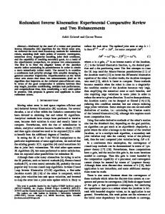
at University of Pennsylvania [4]. A Peabody figure is composed of segments connected together by joints '. Each joint has several degrees of freedom subject to joint limits and users' adjustment. Using graph terminology, the data structure of the Peabody figure is a tree, where segments are nodes and joints are edges. An example of human body model is illustrated in Figure 1. A spatial constraint involves two parts. The constraint parts on the figure are called the end effectors and their counterparts in space are called the goals. In certain contexts, goals and constraints are synonymous, For example, a position goal is satisfied means that a position constraint is satisfied. Associated with each goal, there is a non negative potential function P such that it is zero if and only if the goal is satisfied. Since we are only concerned about the spatial constraint, and the spatial position and orientation are determined by a point and two vectors (a coordinate frame has three basis vectors, but we can only place two of them in the space), the potential P is, in general, the function of a position and two unit vectors, say,
P = P(r, vi, v 2 ) where r is the position vector, and v 1 , v 2 are two unit vectors. Of course, we cannot place two unit vectors arbitrarily. Their angle must be preserved. We call it the potential because it depends only on spatial variables. To form a constraint, we just plug into P the appropriate variables of the end effector which are in turn the functions of the joint angles, i. e. P(O) = P(r(O), v,(0), v 2(0))
(1)
where 0 is the vector of the joint angles. Suppose we have m constraints, then the overall potential is defined as P(O)
, w 1P,(o)
=
(2)
where w, are weights put on the ith constraint, and Pi is the potential associated with the ith constraint. Clearly all the constraints are satisfied if and only if P is zero. In general. constraints are not satisfied simultaneously. Our task is to minimize the potential function subject to joint limits. In most cases, joint limits are described by linear equalities or inequalities, such as lower 'Actually, Peabody figures are graph-structured rather than being limited strictly to trees. For this discussion. however, the tree structure of the human or robot model suffices.
4
head
neck
left shoulder
thorax 1
,right shoulder/
(left upper arm)
lumbar 3
r ight upper arm)
(left lower arm)
lumbar 2
ight lower arm)
( leftand
(
lumbarl1
left upper leg (left
(
right upper leg
lower leg )
left foot
right hand
right lower leg)
right foot
)(
Figure 1: An example of a Peabody human figure model
5
limits and upper limits. So the technique of nonlinear programming with linear constraints is used. Formally, the problem is
{
minP(O) s. t. aTO = bi, i = 1, 2, .... 1
(3)
aTO


![[pdF] Download Time: Limits and Constraints (Study of ... - Google Sites](https://m.moam.info/img/260x300/pdf-download-time-limits-and-constraints-study-of-_647816b3097c47a9708c704c.jpg)


