linear behavior in an advanced steel design course, its ability to model ... that statics and mechanics of materials are taught before structural analysis, that static ...
Section 1526
Real-time, Non-linear, Dynamic Simulation in Teaching Structures: Elementary to Advanced Kirk Martini Department of Architecture, University of Virginia
Abstract The paper describes a project to develop software and teaching methods which employ real-time non-linear dynamic structural simulation in topics ranging from introductory statics to advanced steel design and earthquake engineering. The software is called Arcade and its computation method is based on a physics engine, a method which has been widely applied in computer games. The physics engine approach can easily model unstable structures with very large displacements, making it well suited to study post-buckling behavior, cable structures, and plastic collapse mechanisms. The program performs computations in real time, so that models respond instantly to input from the keyboard and mouse with a game-like interface. While the program has proven effective in lecture demonstrations and course assignments for studying nonlinear behavior in an advanced steel design course, its ability to model unstable structures also makes it useful in teaching elementary statics, since it can model the response of free-floating bodies to unbalanced forces. In addition, its visual presentation makes it suitable for nonengineering students, and the program has been used to teach statics in architecture courses. The program is also ideally suited to teaching concepts of structural redundancy and anti-terror design, since it is possible to see the response of a structure when members are removed interactively: e.g. removing a member from a loaded truss by clicking on the member. The paper describes the program and the teaching methods that have employed it, including lecture demonstrations, a homework problem, and a laboratory exercise. Overview There is a well established and sensible tradition in engineering education that a curriculum begins with basic subjects and then incrementally increases the range of phenomena considered and the sophistication of their analysis. In structural engineering education, this tradition means that statics and mechanics of materials are taught before structural analysis, that static analysis is taught before dynamic analysis, and that linear analysis is taught before non-linear analysis. As computer-based analysis has become common in engineering education, it has followed this tradition. As typical curricula progress, students use computational tools commensurate with their theoretical knowledge, beginning with static linear analysis and working their way up to more complex methods accounting for dynamics and non-linear phenomena. This paper describes a project which turns this tradition around, demonstrating that advanced computational methods can be used effectively not only for advanced topics, but also for elementary topics. The project centers on a computer program, called Arcade, which applies non-
linear, dynamic, time-history analysis – typically a graduate-level method – to teaching elementary statics and physics in addition to advanced topics concerning non-linear behavior. Arcade and associated materials have been tested in structural design courses in the Department of Architecture and the Department of Civil and Environmental Engineering at the University of Virginia. The courses have ranged from a first course in structural design for architecture students, to an advanced course in structural steel design aimed at graduate students and fourthyear undergraduates in civil engineering. The following discussion outlines the computational method and then presents example applications of the program in teaching. A note on presentation: one of the distinguishing aspects of Arcade is the on-screen movement of the structural model, and its real-time, game-like response to mouse clicks and key strokes. This quality is, of course, difficult to convey in static images. Most of the examples in this paper use stop-motion renderings of the animations constructed from screen dumps with image editing software, giving an approximate sense of the animated models. Computational Method Arcade uses a computational method called a physics engine, which is widely used to achieve visual realism in computer games and graphics. A simple implementation of this method involves modeling an object as a collection of point masses connected by springs, and then performing a time-step simulation, solving the differential equations of motion with each step1,2. In computer games, the calculation loop runs in real time, so the on-screen model responds immediately to input from a game controller. As a structural analysis method, the physics engine approach has two key features: •
Large displacements: All calculations are done with respect to the deformed geometry of the structure.
•
Unstable structures: Since a physics engine does not assemble a global stiffness matrix, it can model structures that are unstable, including cables and kinematic mechanisms.
These features make it possible to model the behavior of free-floating objects with forces applied, something which conventional structural analysis programs cannot model because the computation method requires that the structure be stable: that is, requires every degree of freedom to have an associated stiffness. The physics engine approach is not bound by this requirement. This ability to model free-floating objects means that a physics engine can be used to teach fundamental topics such as the effect of forces on particles and rigid bodies, where rigid bodies can be approximately modeled as collections of particles connected by stiff elastic springs. When structural engineering theory is used to extend the characteristics of the springs to account for flexural and axial material yielding, the approach can model a wide range of non-linear structural phenomena, including post-buckling behavior of columns and frames, snap-through phenomena of arches, and frame collapse mechanisms resulting from seismic loading or the loss of a member due to blast3,4.
Proceedings of the 2005 American Society for Engineering Education Annual Conference & Exposition Copyright © 2005, American Society for Engineering Education
Software Features for Teaching Unlike most structural analysis programs, Arcade is designed to serve specific needs of teaching. One such feature is the ability to define a set of input files as a slide show, so that a lecture speaker can advance from one file to the next by pressing a key, similar to the way that PowerPoint can advance from one slide to the next. This feature makes it possible for a speaker to use a dozen or more analysis models in a continuous logical progression, without the visual distraction of closing and opening a new file for each model. Another simple feature is the option to use large display fonts, since font sizes appropriate for an individual working at a desk are typically illegible to an audience viewing the projected screen image in an auditorium. Although mundane from a technical standpoint, these features have an enormous impact on the program’s effectiveness as a teaching tool, allowing a much clearer and more engaging presentation of ideas than conventional structural analysis software, which is typically optimized to serve a single desk-bound user. With the ability to present a collection of input files as a set of slides, several slide sets have been developed for a range of topics. The following discussion includes selected slides from some of these sets, beginning with the elementary topics and progressing to more advanced. Particle Motion Under Force Studying the response of a particle mass to force is one of the simplest problems in physics, and is the traditional starting point for the study of force mechanics. Despite the simplicity of the problem, conventional structural analysis programs cannot model the response of a particle to forces, because the system has no stiffness. The tradition in structural engineering is that students need to learn particle mechanics before they can use or understand a structural analysis program. With the physics engine approach, computer analysis can be used to teach concepts of particle mechanics, allowing computer analysis to be introduced in the first stages of the curriculum. Figure 1 shows an example of an extremely simple Arcade model consisting of a particle with a single force applied. When the simulation begins, as expected, the particle accelerates in the direction of the force. Figure 2 shows a more complex example illustrating the parallelogram rule for forces. In this example, there are two particles, each with a different force system. The simulation shows that the two particles have the same motion, which means that the two force systems are equivalent (this is easier to see when viewing the animation which shows the particles moving in synchronization). By counting squares of the background grid, it can be shown that the force on the right is the diagonal of the parallelogram formed by the first two forces: e.g. starting from the particle on the right, count up four and over one (the first force on the left) and then right three and up one (the second force).
Proceedings of the 2005 American Society for Engineering Education Annual Conference & Exposition Copyright © 2005, American Society for Engineering Education
Model of particle with force, shown before the simulation begins.
Stop-motion rendering of the simulation, showing the response of the particle to the force.
Figure 1: Simple particle mass with force.
Model with two particles with different force systems.
Stop-motion rendering of simulation, showing that the motion is the same for the two particles.
Figure 2: Particles with equivalent force systems. Moving ahead in the slide set to a more complex example, figure 3 shows a model with two particles with different force systems, labeled A and B respectively. The situation is described to the class: one of the force systems is in equilibrium and the other is not, first determine which is not in equilibrium, and then describe how that one will move. Students are asked to group into pairs and develop and answer, according to well-known active learning techniques5. The answer can be found simply by counting grid squares of force components vertically and horizontally for each system. After students have discussed and explained their answers, the simulation is run, showing that particle A accelerates to the left, as predicted by the square-counting calculation. The discussion then turns to the question of how the force system acting on particle A can be modified to put it in equilibrium, and the modification is made to the model and tested in simulation. This approach has two key advantages. First, the device of drawing forces to scale on a grid allows problems to be solved with simple integer arithmetic, so the discussion focuses on physical concepts of force balance rather than the details of calculating vector components, which are introduced later. Of course, that method could be used in a paper-based presentation of the problem, which leads to the second advantage. The program’s ability to simulate the physics provides a mechanism to check the answer, and to immediately see how the response changes when the force system is modified. This capability is particularly important when questions arise during lecture concerning the effect of changes to the system. If a student proposes a change to the system on particle A to put it in equilibrium, the change can be made on Proceedings of the 2005 American Society for Engineering Education Annual Conference & Exposition Copyright © 2005, American Society for Engineering Education
the spot and tested, which may lead to further discussion depending on whether the proposed change is correct. The ability of the program to model the effect of forces can be applied to bodies as well as particles, as discussed below.
Two particles with different force systems. One is in equilibrium and one is not.
Stop-motion rendering of the simulation. Particle A has an imbalance of horizontal force components, while particle B is in equilibrium.
Figure 3: Two particle systems with one in equilibrium. Rigid Body Motion Under Force Progressing in complexity of statics topics, the following discussion concerns a homework assignment based on a rigid body with an unbalanced force system, shown in figure 4. The system’s horizontal and vertical force components are balanced, but the moments are not balanced; the simulation shows that the body rotates clockwise. The task given to students is to add two forces to the body which put it in equilibrium. The correct answer is any two forces that produce a counterclockwise couple of 800 kip-feet (the grid in the figure has a module of 10 feet). The problem has two notable characteristics. First, unlike most problems in a statics course, there is no single correct answer; an infinite number of couple configurations can produce the required balancing moment. Second, the program gives instant feedback on a proposed answer: if the answer is correct, the model remains stationary, otherwise the model moves. The type of movement gives a hint about how the answer is incorrect: clockwise movement means their couple is too small, counterclockwise movement means it is too big. Working with such problems gives students an opportunity to develop experience and intuition concerning the response of free-floating bodies to force systems, a situation that rarely occurs in everyday life, but is essential to understanding force mechanics.
Proceedings of the 2005 American Society for Engineering Education Annual Conference & Exposition Copyright © 2005, American Society for Engineering Education
Body with rotationally unbalanced force system.
Stop-motion rendering of the simulation, showing the response of the body to the force system.
Figure 4. Body with unbalanced forces. Students must add two forces which put the body in equilibrium
Truss Behavior and “Zero Force” Members Analysis of statically determinate trusses is another topic typically found in a statics course. The following discussion involves a lecture demonstration concerning the 10-panel truss shown in figure 5. In the simulation, shown in the lower part of the figure, the truss is rendered to show the magnitude and sense of the axial force in the truss members. The thickness of the line indicates the magnitude of the member force, and the color indicates the sense of the force: red for compression and blue for tension. After discussing the patterns of member forces in the truss, the subject of zero force members arises, since it is clear from the rendering that almost all of the verticals and two of the horizontals are extremely thin lines, meaning very low force. There is inevitably a question about whether such members are necessary, a question that can be answered using Arcade’s “bomb tool.” With the bomb tool, a user can click on an element in the model while a simulation is running and the element is immediately removed. Experimenting with the bomb tool reveals that removing some verticals, such as the third or fifth from the left, has no visible effect on the truss, while removing others, such as the fourth from the left, cause the truss to collapse, as shown in figure 6.
Proceedings of the 2005 American Society for Engineering Education Annual Conference & Exposition Copyright © 2005, American Society for Engineering Education
10-panel truss with overhang.
Rendering of simulation where line thickness indicates the axial force. The color indicates force sense: red for compression and blue for tension.
Figure 5. 10-panel truss and rendering of simulation showing bar forces.
Figure 6. Collapse of the truss initiated by using the bomb tool to remove a “zero force” member: the fourth vertical from the left. Note the bomb tool cursor near the removed member. The reason that the force is near zero in the vertical members is explained in any statics textbook; when a truss joint has a condition of three forces converging where two forces are inline, then statics dictates that the third force is zero6. Traditionally, texts explain that even though the forces calculate to zero, the members are often necessary as secondary bracing. Working with the Arcade model makes it possible to elaborate on this point as follows: •
In real structures, forces are rarely perfectly in-line. The statics rule for zero force members applies to the case where there are three forces and two are in-line. This rule is typically applied on the assumption of first-order behavior: that is, using the undeformed geometry of the structure. Considering the geometry of the deformed structure, as Arcade
Proceedings of the 2005 American Society for Engineering Education Annual Conference & Exposition Copyright © 2005, American Society for Engineering Education
always does, members that are aligned in the undeformed structure probably will not be after load is applied. •
“Zero-force” members bracing tension members are far less important than those bracing compression members. Experimenting with removing various zero-force members, students eventually notice the pattern that the structure collapses when the zero-force member was bracing two compression members (as shown in figure 6), but does not collapse when the zero force member was bracing two tension members. They can understand that after removing the bracing member, nearly aligned tension members will straighten out to an in-line configuration, while nearly aligned compression members will fold inwards, forming a collapse mechanism.
•
Compression bracing is one of a structure’s most vulnerable points. The catastrophic effect of removing compression bracing underscores an important aspect of structural behavior; compression bracing is a highly vulnerable point in a structure. Considering design from an anti-terror perspective, secondary compression bracing members typically have much lighter sections than those of the primary compression structure that they brace. Removing that lightweight bracing can lead to collapse of the entire structure, making it a likely target of a terror attack.
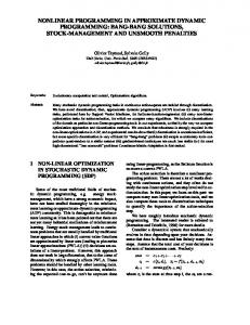
This example illustrates that working with the dynamic non-linear simulation in the context of an introductory statics course makes it possible to introduce substantive discussion of second-order behavior and anti-terror design, topics that would normally arise, if at all, only in advanced structural design courses in the graduate or late undergraduate engineering curriculum. Frame Buckling The discussion now turns to a more advanced topic: frame buckling. Figure 7 shows a model used in teaching an advanced engineering course in steel design; it is based on a textbook example problem7. The model includes a graph where the vertical axis represents the total of the vertical reactions, and the horizontal axis is the average of the vertical displacements at the tops of the two columns (Arcade provides a facility for real-time graphing of combinations of several node-related quantities such as displacement and unbalanced force). Each column is modeled using four elastic beam elements, and the nodes of the columns are positioned to given an out-ofplumbness of L/1000. The graph illustrates the nature of side-sway frame buckling: the vertical stiffness is linear up a point, and then transitions to near zero stiffness. The pop-up window on the graph shows the values of the force and displacement at the point indicated by the upper left corner of the window; such a window can be summoned by right-clicking any point on the graph. The window in the figure is near the point where the stiffness begins to deviate from its initial linear value. The theoretical column buckling load is 1500 kips for each column, meaning 3000 kips for the entire frame. As shown in the graph, the frame initiates buckling at about 2800 kips, and then plateaus at 3000 kips. The initiation of buckling before the theoretical value is the result of the out-of-plumbness.
Proceedings of the 2005 American Society for Engineering Education Annual Conference & Exposition Copyright © 2005, American Society for Engineering Education
This example underscores important aspects of frame buckling. One is the effect of out-ofplumbness. Varying the out-of-plumbness shows that the degree of out-of-plumbness influences the load at which buckling initiates (when the load displacement curve deviates from linear), but does not change the maximum vertical load (the height of the plateau). More importantly, watching the animated image of the frame makes clear that for a side-sway frame, it is necessary to conceive buckling as a phenomenon involving the entire frame, rather than individual columns.
Figure 7. Stop-motion rendering of side-sway buckling frame from a textbook example. The pop-up window on the graph is the result of a right-click.
Design for Blast Load World events over the past decade have created a heightened awareness of blast-load design in the structural engineering community, yet there is a limited selection of computational tools suitable for undergraduate teaching that can account for the dynamic, non-linear phenomena associated with blast load. One effective tool for such phenomena is the NONLIN program8. developed by Finley Charney and freely available from the Federal Emergency Management Agency. Despite its effectiveness, NONLIN has an inherent limitation in that it can model only single degree of freedom systems. The following example illustrates how Arcade incorporates some of the functionality of the NONLIN program, including defining load histories and graphing, in a laboratory exercise for blast design with a multi-degree-of-freedom system. Figure 8 shows a simplified model of a vertical truss acting as lateral-load bracing for a 40-foot tall wall, as might be found enclosing a large public room. The model shown is the starting point for the 90-minute laboratory exercise in an advanced architecture course on structural design for dynamic loads. The loading is a triangular impulse load applied to the three interior nodes on the Proceedings of the 2005 American Society for Engineering Education Annual Conference & Exposition Copyright © 2005, American Society for Engineering Education
left chord of the truss. The maximum magnitude of each load is 4000 kips, with an impulse duration of 3.7 milliseconds. The load properties were calculated using the ATBlast program9, developed by Applied Research Associates, and freely available from the General Services Administration. The load correspond to a charge of 100 pounds of TNT at a distance of 30 feet. All elements in the model are inelastic truss elements using bilinear stiffness; the elements can be set to be removed from the model if the tension strain exceeds a threshold value, modeling tension fracture. The model includes short vertical links at the top and bottom of the truss which represent the displacement and force capacity of the structure that supports the truss. Those links yield at a force of 500 kips, and fracture at an extension of 3 inches. Figure 9 shows a stop-motion rendering of the simulation for the initial model. The stop-motion snapshots are taken at intervals of 4 milliseconds, with the entire motion shown in the rendering taking 12 milliseconds (the program is set to show the animation of response in slow motion). The yellow color of some members indicates material yielding. The graph to the right of the rendering shows the structural resisting force on the vertical axis, calculated as the sum of the horizontal support reactions, and the structural displacement on the horizontal axis, represented by the horizontal displacement of the mid-height node on the left chord. Each dot on the graph corresponds to a snapshot in the stop motion rendering.
Figure 8. Starting model for blast load laboratory exercise. The sudden drop in the graph corresponds to the failure of the vertical links in the starting configuration. The simplified criteria for the lab exercise require students to reconfigure the truss so that under the blast load, the vertical links do not fracture, and that the total horizontal resisting force does not exceed 1000 kips. Students are allowed to change the cross section area of any member, the profile of the right chord of the truss, and are also allowed to add Proceedings of the 2005 American Society for Engineering Education Annual Conference & Exposition Copyright © 2005, American Society for Engineering Education
superimposed mass to the nodes. The objective is to meet the criteria with minimum weight, where the weight includes the structural self weight plus the weight of the added mass.
Figure 9. Stop-motion rendering of starting truss design subjected to blast load. The snapshots are taken at the times 0, 4, 8, and 12 milliseconds, with each snapshot corresponding to a dot on the graph. Members rendered in yellow indicate material yielding. The pedagogic objective of the exercise is to make students conceptualize the structure as a system to absorb energy with controlled levels of force and displacement, rather than as a system to resist loads. Experimenting with the design variables of the problem, students quickly observe that the force levels in the structure depend on the structure itself. Structures with high strength and low mass have much higher force response than those with low strength and high mass. The structure needs to be ductile to absorb the energy, but if the inelastic displacement is too high, the structure will exceed the vertical displacement limits at the supports. Figure 10 shows a successful student-generated redesign of the truss. The dots on the graph correspond to the state of the truss at 10-millisecond intervals. The vertical drop of the graph does not correspond to a structural failure, but rather to the elastic rebound of the structure after it has fully absorbed the kinetic energy imparted by the blast impulse. The primary modification made by the student was to add superimposed mass to selected nodes and to make adjustments to the truss profile and member sizes to reduce its strength and weight; this combination produces much better performance, allowing the structure to fully absorb the kinetic energy generated by the blast and stay within the force and displacement limits of the problem. There are many aspects of this problem which are highly simplified, for example, it does not model buckling of compression members. In addition, the links modeling the capacity of the Proceedings of the 2005 American Society for Engineering Education Annual Conference & Exposition Copyright © 2005, American Society for Engineering Education
supporting structure are highly simplified, and the limiting values of force and displacement are arbitrary. It would be possible to produce a more sophisticated model by using beam elements rather than truss elements and adding other refinements, but that would be more appropriate for an extended homework assignment. The primary objective of this short laboratory exercise, is to illustrate that the goal of a blast resistant structure is to absorb energy rather than resist forces.
Figure 10. Truss redesigned by student. The snapshots are taken at the times 0, 10, 20, 30, and 40 milliseconds, with corresponding dots on the graph.
Limitations Although Arcade can be applied to a wide variety of situations, it does not replace the need for other types of analysis software. The following listing identifies limitations of the physics engine computational method and Arcade’s implementation of it. •
The physics engine approach is limited to time-history analysis. There are many problems in dynamics where it is useful to consider the characteristics of a structure’s modes of vibration. The physics engine approach is limited to time-history analysis, and so cannot perform a modal analysis.
•
The physics engine approach is not well suited to large problems. The physics engine approach is extremely computationally intensive, particularly for engineering structures with realistic stiffness because it requires an extremely small time step to be stable. It is best suited to small-scale problems useful to teach structural behavior. In today’s computing environment, it would not be a suitable choice for the complete analysis of a 50-story building frame. Proceedings of the 2005 American Society for Engineering Education Annual Conference & Exposition Copyright © 2005, American Society for Engineering Education
•
Arcade has a limited library of elements. The Arcade element library has four element types available (elastic and inelastic truss elements, and elastic and inelastic beamcolumn elements). Many important problems require more sophisticated elements.
•
Arcade is limited to two-dimensional analysis. Many important structural engineering problems require three-dimensional analysis, while Arcade is limited to two-dimensional analysis.
The inability of the physics engine approach to consider vibration modes is an inherent limitation of the computation method. The limitations on problem size will, of course, be less restrictive as computers continue to grow in speed and capacity. Arcade’s limited element library reflects its current early stage of development. The limitation to two dimensions in part reflects the stage of development, but also reflects pedagogic objectives of the project. One of the goals is that instructors be able to introduce the program into a course without spending significant time teaching details of its operation. There is a high priority on ease of learning. Supporting three dimensional analysis runs counter to this goal because it would require a significantly more complex graphic interface, as well as requiring more data to define element properties and orientation. For the near future, the project development will emphasize an easy-to-learn program which supports non-linear, time-history analysis of relatively small-scale, two-dimensional models for the purpose of teaching structural behavior. The goal is that Arcade become a versatile tool in an instructor’s tool box, used to complement software that can perform other tasks, such as modal analysis of large structures. Conclusions In a traditional structural engineering curriculum, a student’s first contact with computer-based structural analysis is typically static, linear analysis, only after courses in statics and mechanics of materials have been completed. Experience with the Arcade program has demonstrated the value of an apparent contradiction: advanced analysis methods can be effective in teaching elementary topics. Using the physics engine approach, non-linear, dynamic analysis can be applied from the earliest stages of the undergraduate structural engineering curriculum, continuing on to graduate-level topics such as inelastic analysis for blast loads. This approach can also allow the early undergraduate curriculum to introduce substantive discussion of traditionally advanced topics such as second-order truss behavior and collapse modes. The physics engine approach has clear limitations, and the Arcade implementation of it includes more limitations, but experience with the program has shown that the game-like instant feedback, combined with the non-linear capabilities enable a completely new role for analysis software in the structural engineering curriculum.
Proceedings of the 2005 American Society for Engineering Education Annual Conference & Exposition Copyright © 2005, American Society for Engineering Education
Acknowledgements This material is based upon work supported in part by the National Science Foundation under Grant No. 0230573. That support is gratefully acknowledged. Any opinions, findings and conclusions or recommendations expressed in this material are those of the author and do not necessarily reflect the views of the National Science Foundation. Bibliography 1.
Hecker, C. (1996) “Physics, The Next Frontier”, Game Developer, October/November, p. 12-20.
2.
Witkin, Andrew, D. Baraff, (1997), : Physically Based Modeling: Principles and Practice: Particle System Dynamics (accessed December 22, 2004)
3.
Martini, K. (2001) “Non-linear Structural Analysis as Real-Time Animation: Borrowing from the Arcade”, Proceedings of the Computer-Aided Architectural Design Futures 2001 Conference, Kluwer Academic Publishers, Dordrecht, Netherlands, pp. 643-656.
4.
Martini, K (2002) “A Particle-System Approach to Real-Time Non-Linear Analysis,” Proceedings of the 7th National Conference on Earthquake Engineering, Earthquake Engineering Research Institute. CD-ROM publication.
5.
Johnson, D., Johnson, R., Smith, K. (1991) Active Learning: Cooperation in the College Classroom. Edina, MI, Interaction Book Company.
6.
Beer, P., Johnston E. R., (1977) Vector Mechanics for Engineers, McGraw Hill, New York.
7.
Salmon, C. G., Johnson, J. E., (1996) Steel Structures: Design and Behavior, Addison Wesley Longman, New York.
8.
Federal Emergency Management Agency (2004), Nonlinear Dynamic Time History Analysis of Single Degree of Freedom Systems, (accessed December 22, 2004).
9.
Office of the Chief Architect (2004) ATBlast 2.1, General Services Administration, (accessed December 22, 2004)
KIRK MARTINI has been with the Department of Architecture at the University of Virginia since 1992. He received a Ph.D. in structural engineering from the University of California at Berkeley. He teaches courses in structural design as well as digital media. His research interests include non-linear analysis, seismic design, and physical modeling for computer graphics.
Proceedings of the 2005 American Society for Engineering Education Annual Conference & Exposition Copyright © 2005, American Society for Engineering Education