email: {gerold, pieter}@ph.tn.tudelft.nl. Keywords: Real-Time Imaging, Stereo ... cessing units, the IMAP- VISION device developed by NEC Corporation Japan.
Real-Time Stereo with Dense Output by a SIMD-Computed Dynamic Programming Algorithm Gerold Kraft
Pieter P. Jonker
Pattern Recognition Group, Department of Applied Physics Delft University of Technology Lorentzweg 1, 2628 CJ Delft, The Netherlands email: {gerold, pieter}@ph.tn.tudelft.nl Keywords: Real-Time Imaging, Stereo Vision, SIMD, Dynamic Programming (DP)
Abstract We present a modified stereo algorithm based on dynamic programming techniques, which outputs a dense disparity map, and its actual implementation on a linear SIMD image processing device with 256 PE, the IMAP-VISION. Our results show the high suitability of this algorithm and the parallel hardware for real-time 3D-vision based robot control. Running on the SIMD device, the algorithm guarantees a processing time of less than 100 ms hard for a Region Of Interest of 128 by 128 pixel and a respectively large depth range of 64 disparity levels. The algorithm can be adjusted with ease and fast at the update rate of the input for even higher output rates, when considering lower depth resolution or less ROI width.
1
Introduction
To obtain 3D depth information in fast and continuous sequence is a very high ranking problem in applications of autonomous operating robots. For matters of image transmission, the term ’real-time constraint’ usually must be expanded as ’video realtime constraint’, i.e. requiring 25 respectively 30 full frame images per second according to common industrial standards. Robotic tasks, our scope in this paper, allow to relax this definition slightly. Any hard realtime sensor input must not exceed the time constant of the controller feedback loop. For the majority of robotic applications this means, we can consider update rates about 10 Hz to fit real-time requirements. The vision and 3D localization system of an autonomous robot must be able to process generic composed scenes. Especially robot systems operating outdoors or in scenes containing natural objects are highly dependent on dense 3D information. We will present an algorithm for passive stereo which will out-
put dense maps of disparity samples. In consequence, this approach focuses on the generation of rich depth data sets, allowing for robust segmentation at a later stage, while it does not match the scene with any specific CAD-metric model already at the stage of early vision. Dynamic programming (DP) techniques are shown to reduce the time complexity of dense stereo search from order O(N M ) towards O(N ×M ), where N and M are the number of features in left, respectively the right image. DP techniques are highly suited for data-parallel implementations, such as on SIMD system architectures, due to their simple algorithmic structure and low computational requirements. Section 2 describes the general structure of a known, non-parallel operating DP stereo algorithm. In section 3 we discuss and show our modifications to that very algorithm towards data-parallel operation on a linear SIMD processor array. Section 4 presents our promising experimental results towards real-time stereo, using an existing highly parallel operating SIMD video processing hardware of 256 processing units, the IMAP- VISION device developed by NEC Corporation Japan. The final section 5 gives the summary of our paper.
2
Dense Stereo using DP Techniques
Dynamic programming is an efficient way to minimize a function of many discrete variables. While using dynamic programming for means of stereo registration, our goal is to find in the discrete space grid, generated by permutations of left and right input image data positions, a joint path of grid cells indicating a global minimum in stereo mismatch. We present to the algorithm two input maps, a left and a right, of data values organized in identical pixel
Different fast methods of stereo matching using dynamic programming have been presented in the past among others by Ohta and Kanade [1] and Lee and Leou [2] for matching of extended line structures, Cox et al. [3], Birchfield and Tomasi [4] and Jeong and Oh [5] for matching pixel by intensity value directly. The structure of the sequential stereo matching algorithm we describe in the following is based on that presented by Cox et al., while we also benefit from the idea of inter-scanline matching early introduced by Ohta and Kanade.
2.1
Interpreting the Stereo Search Space as a Markov Random Field
Exploiting epipolar geometry, we first reduce the stereo matching problem from a 2D search into a 1D search along straight epipolar lines. We assume left and right input to be processed in a rectification step beforehand, such that corresponding epipolar lines have been identified, and are now presented by corresponding image scanlines. Registration of matching pixel positions becomes a problem of O(N 2 ) in this case, assuming N discrete sample positions equally at both, lefty and right, epipolar lines from the input. Generally, any valid object depth in the discrete search space can not perform independent from neighboring solutions since they must represent physically cohesive constrained object surface. Therefore we interpret the discrete stereo search space, which is created by two epipolar lines, as a 2D Markov Random Field (MRF) of many discrete variables or nodes, inter-connected by transitional dependencies. While each variable, also called a node of the MRF, measures the similarity of data from corresponding spatial permutations in the left and the right epipolar line, its distance to the main diagonal of the square MRF matrix can be interpreted as a value for disparity, or in consequence, a depth measure for that correspondence. Let the scene contain a single ideal Lambertian reflective surface, which introduces no occlusions in any of both camera views. Those nodes in the MRF will show maximum similarity (or, respectively, minimum dissimilarity due stereo mismatch) for their respective input samples, if these input samples refer to
Left camera epipolar line
0
1
2
3
4
5
xLeft Right camera epipolar line
grid resolution. We obtain a dense output map containing disparity values for all matching pixel positions and occlusion indications in the other case. The output map has the same resolution as the input. For reason of symmetry, i.e. in order to present left and right occlusions in the same output map, we choose the cyclopedian eye position in the middle between both stereo cameras as the origin of the disparity map frame.
0 1 2 3 4
2
5
xRight
-1
3
4
5
1 disparity=0
Figure 1: Discrete stereo search space introduced by two epipolar lines. very the same point onto the 3D object surface. We search the MRF, while following the transitions between the nodes, for exactly one joint path of minimum stereo mismatch, which is also the representation of the continuous 3D object surface. If we note the position of the nodes we visited on this path relative to the MRF main diagonal, we easily reconstruct the disparity values along the scanline.
2.2
Constraints to Consider
We can assume that match positions are constrained by strict ordering along the epipolar lines. In this case, the stereo search space, as shown in figure 1, reduces to half of the original size and becomes the upper triangular matrix only. The assumption of an ordering constraint holds true for a strict parallel stereo setup. Hence in the general case, considering input from stereo cameras mounted at angle, the input will not fit any strict ordering constraint. But practically, stereo setups are preferably mounted in nearly parallel orientation, and ill-conditioned objects in the near-camera field can be identified else. When searching the MRF by dynamic programming for a minimum cost path, we need to introduce a direction attribute to the transitions between the nodes. Since we are operating in a 2D rectangular organized grid, each node, except those at the borders of the MRF, features three inputs and one output. Any first pixel we choose in order to initiate a stereo search, does not allow the DP algorithm to reason for its very disparity value since those MRF nodes will have no predecessor input in the 2D Markov chain. If it is not a background pixel, i.e. it has not truly zero (or else known) disparity value, all in consequence processed pixel positions in the Markov chain might become initially biased by an unknown disparity offset.
disparity 5
j :
E(i-1, j+1) 4
E(i-1, j)
3
E(i, j-1)
2
+ WDiscontinuity
gi+jLeft
+ WMatch
E(i,j)
+ WOcclusion gi Right
1 S site i :
0
D 1
2
3
4
0
5
Figure 2: The stereo search space as a MRF structure consisting of nodes and directed transitions. A simple DP algorithm starts at the node S and visits all sites i while it follows the transitions, until it reaches node D. From there it traces back to S and outputs the actual disparity level j each step.
2.3
Processing the Stereo–MRF using Dynamic Programming
In order to process the 2D – MRF of the stereo search space by dynamic programming techniques, we address the nodes in the MRF along an axis of sites and an axis of levels orthogonally. As the axis of sites we chose the main diagonal of the MRF matrix, also representing the set of all possible matches of true zero disparity. The axis of levels we consequently chose to represent the possible disparity values to search. The technique of dynamic programming evaluates the discrete 2D – MRF structure in two passes, a forward programming pass which propagates cost values, and backward pass which tracks back exactly one minimum cost path. In the forward pass we evaluate sites sequentially, starting from an initial position, until we reach the final site. Evaluation of a site means, we evaluate all levels of this site, possibly employing dataparallelism. In the backward pass we start at the final site that we reached the pass before and trace sequentially back a path of minimum cost from in memory stored information at the MRF nodes. The sequential processing of the sites in both passes efficiently can be implemented as repeated operations in-situ.
Figure 3: Each MRF node updates the input stereo mismatch error E it get offered from predecessors, decides on one to select and notes that predecessor to memory, before it passes the selection to its successor node.
ues E from its closest three predecessor neighbors. Each transition increments the transmitted data by its specific cost value W. Any node in the MRF selects and memorizes the source node offering the actually minimum total error. This error value then will become avail for input request from the direct successor nodes: E(i − 1, j + 1) + WDiscontinuity E(i, j) = min E(i − 1, j) + WM atch E(i, j − 1) + WOcclusion (1) If we follow a transition of increasing disparity, we accept occlusion of areas with greater depth in the stereo search process. A depth discontinuity is present if the object surface is actually visible but bending away from the camera position, forcing us to continue the search at a lower disparity level. The costs for occlusion and discontinuities in depth are constant terms. For the specific case of an a-priori known probability for depth discontinuity occurrences, Cox et al. [3] show the exact computation of these costs. Although, in most real scenes this probability is very unlikely to be known. Therefore we heuristically determine these costs to fit the condition WOcclusion ≥ WDiscontinuity . The actual cost of a stereo match WM atch we compute robust as Lef t WM atch = k · giRight − gi+j � � Lef t + (1 − k)· gb − min(giRight , gi+j ) ,
(2)
2.3.1 The Forward Programming Pass In the forward pass we increment and propagate values of mismatch error from the actual site towards the next site. Exemplary (as shown in figure 2) we start with the leftmost node in the triangular MRF as initial node and loop through the number of sites until we reach the rightmost node. Due to the rectangular structure of the MRF grid, each node receives accumulated mismatch error val-
Lef t where giRight and gi+j are the intensity values at the indicated scanline position and gb an upper bound of intensity in the image. We assume object pixel to have originally higher intensity values than background pixel. The heuristic constant k ∈ [0, 1] therefore balances the objective measure of pixel similarity and our subjective trust in this match due to object visibility.
2.3.2 The Back-Tracking Pass Since each node memorized the input source position it selected, we can trace back with ease from any chosen position in the MRF the complete minimum cost path from node to node, following the transitions in counter-direction until we reach the initial node we started at. At the intermediate stop each reviewed MRF node we note its corresponding disparity value, or respectively, the presence of occlusion.
3
SIMD Computed DP–Stereo
Most Single Instruction – Multiple Data (SIMD) computer architectures introduce for operation multiple and connected Reduced Instruction Set Computer (RISC) Processing Elements (PE), usually operating in synchronous mode. DP based algorithms are highly suited to be implemented on such RISCtype hardware. Dynamic programming basically employs accumulative addition and comparison operations only. Also these algorithms easily can be implemented using integer arithmetics only.
3.1
Mapping the DP–Stereo Problem onto a linear SIMD Array
As we showed in section 2.1, a DP based stereo search algorithm requires for each epipolar scanline a triangular shaped 2D–structure. As mentioned, DP evaluates sites axis in sequential order. Hence, with subject to data-parallelism, the evaluation of multiple disparity levels, or to process multiple pixels along one epipolar line instead, are alternative choices. Although, in order to achieve maximum performance, the distribution of computational load should not set PE idle, i.e. let PE perform operations based on dummy values. One can find usually a low limit to the requested Disparity Levels Of Interest (DOI), so one has to search a much smaller range than the full length of both epipolar lines. A proper selection of the DOIbound depends on the current amount of objects in the scene and the expected structural complexity of the visible object surface. To our knowledge, all relevant approaches described in the literature focus on the data-parallel evaluation of pixels by linear SIMD array structures, hence they process epipolar scanline separately in sequence. Assuming the height of a xy-spatial Region of Interest (ROI) as a constant, we rather propose to evaluate multiple epipolar scanlines data-parallel. Given a linear SIMD array, we leave access on pixel level subject to a sequential sub-procedure. A 2D – SIMD matrix could data-parallel access pixels and evaluate multiple epipolar lines. But with respect to the issue to adapt certain parameters in a dynamically changing
D site i :
0
S 1
2 PE 1
D 3
4
5
PE 2
Figure 4: Processing a epipolar line by the multiple wavefront approach, using 2 PE. Pixel 2 is known to be a background pixel in left and right view. Therefore we assume zero disparity (infinite depth) for it. environment fast, the choice of a 2D – SIMD matrix leaves one with less flexible and efficient DP implementations than an 1D-array architecture does. Aiming to quasi-static environment scenes, Laine and Roman [6] developed for 2D – SIMD matrix structures a fast stereo algorithm based on relaxation labeling. If the total number of PE is significantly smaller than the total number of pixels on the epipolar line, a parallel computation of the DOI range will show good performance. The authors of [7] present a SIMD– hardware with 9 PE, evaluating the DOI for each pixel along the epipolar line in a systolic process. If the total number of PE reaches in the order of the length of the epipolar line, the DOI–parallelization of one epipolar line only obviously introduces a very uneven computational load not constant over time, which leaves available PE running idle at sites where the remaining DOI range less than the PE amount. In this case, a data-parallel evaluation of pixels along an epipolar line might be thought to give better performance, since it will set less PE idle. But still, the computational load is not constant over processing time. Therefore we propose to evaluate data-parallel multiple epipolar scanlines instead, using (at least) 1 PE at each epipolar line.
3.2
Bi-Directional Stereo Search
As we argued in section 2.2, in order to succeed with the DP algorithm we need to know well the disparity value of at least one initial position along each epipolar line. Usually the search is meant to start at the leftmost pixel of a scanline. But, more precisely, one can start from any arbitrary pixel position along the epipolar line (preferably close to the image center), if the disparity value at that very position is known a-priori. The DP algorithm evaluates now the epipolar line in two wavefronts, one processing towards the left-hand and the other towards the righthand end of the epipolar line. Each wavefront can be
processed using a different PE, hence we spend 2 PE each epipolar line in total.
3.3
Using Inter-Scanline Dependencies
We assume the input maps are corrupted by noise and sampling artifacts at intensity edges, causing noisy vertical shape artifacts in the output disparity map. Therefore we correlate the search results of neighboring epipolar lines close to each other in order to reduce noise, while we exploit communication between neighboring PE in the SIMD architecture. In a first approach we let in the DP forward pass each MRF–node access not only its predecessors operating at the very same scanline, but also those predecessors it would have when operating one epipolar line above and one below. Thus, by means of inter-scanline communication, each node effectively has now 9 inputs to choose the minimum of instead of 3 before. In experiments we found the benefits of this approach highly comparable to those when one would apply a slight defocus to the stereo cameras. In best case this approach showed in our implementation still about 30% to 40% additional computational load compared to the original DP algorithm. Also, this approach does not allow to compute epipolar lines in multiple wavefronts by different PE. In a second approach we correlate the selection process of a proper minimum error path during the back-tracking pass. While the DP algorithm follows back the minimum mismatch path through the nodes, we established a majority vote of those nodes placed at identical position at neighboring epipolar lines on the subject which minimum error path to follow. In fact, this approach applies a dynamic median filter on the disparity output, showing better results than a conventional median filtering of the ready-computed disparity map output afterwards. Also note, the additional computational time complexity of this approach is the same low than that of a conventional median filter. Therefore we favor this approach in our actual implementation.
4
Experimental Results
In our experiments we use the IMAP-VISION image processing device, developed by NEC Incubation Center, a subdivision of NEC Corporation Japan. Computational operations on the IMAP-VISION are performed by a linear SIMD array consisting of 256 PE, which are clocked synchronously at a 40 MHz operation cycle speed. Each PE is a 8-bit integer RISC processor with a local register cache memory of 1 KB, comparator, adder and bit-shifter unit. Hence, due to the RISC architecture, it efficiently can perform addition and extremum selection operations, but multiplication and division by arbitrary numbers, which are
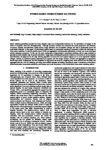
(a) Input Overlay Display
(b) Dispartity Map Output of Center ROI
Figure 5: Top: Left and right stereo input, greylevelinverted and combined by a minimum operation, showing background pixel of known zero disparity in white. Bottom: Output disparity map in a 128x128 pixel ROI. not powers of 2, are necessarily executed in software. The hardware of the IMAP-VISION also implements a method for fast barrel-shifting of data words towards and through neighboring PE, thus allowing exchange of data in small PE–neighborhoods. Single PE can be disabled by a mask register bit and thus be hidden from participation at computations. In our implementation we compute each epipolar scanline by 2 PE, as we discussed before in section 3.2. Therefore we can process 128 scanlines dataparallel with all 256 PE of the IMAP-VISION, leaving none PE running idle on dummy values. The width of the xy-spatial ROI is limited only by the total image width. Exemplary we refer to a square ROI of 128 by 128 pixel. The actual width of a ROI refers also to the number of disparity levels we at most can
disparity [pixel] 16
32
64
128
hardware IMAP PIII-866 PIII-450 IMAP PIII-866 PIII-450 IMAP PIII-866 PIII-450 IMAP PIII-866 PIII-450
ROI width [pixel] 32 64 128 6 14 28 12 28 59 24 54 114 8 22 52 16 48 103 31 87 199 30 85 59 171 116 331 111 228 440
Table 1: Computation time of the dynamic programmed stereo algorithm in milliseconds, running on the IMAP-VISION (256 PE, 40 MHz) and on single-processor PC hardware based on Intel PentiumIII at 866 MHz and 450 MHz, dependent from disparity range and ROI width. Results refer to a ROI height of 128 scanlines. process. Although, dependent on the scene, usually a much smaller number of disparity levels is sufficient. Because we do not map the number of disparity levels to the SIMD array hardware, neither the length of epipolar lines, but process instead these dimensions sequentially, we efficiently can tune these limits in real-time at input frame rate. We examined the computation time our implementation requires to process different sizes of the ROI and different ranges of disparity levels. Also, we compare the SIMD computed results of the IMAPVISION to data-serial implementations on Intel PC processor hardware suitable for autonomous mobile robot setups. The results in table 1 illustrate the ability of our modified DP algorithm to perform a dense stereo search in real-time using SIMD hardware. Regarding our reference of 128 by 128 pixel spatial resolution, we can search a large range of 64 disparity levels within 85 ms. We note, preprocessing and rectification of the full stereo input for epipolar geometry can be done on the SIMD hardware as well and require together a constant and low time amount of 11 ms additionally, not contained above in table 1. The algorithm code has high locality and is entirely based on integer operations. Therefore it efficiently can be implemented at PC hardware, where it scales well with the cycle speed of the actual main processor. Although, any actual autonomous robot architecture would require a powerful second PC processor specially designated for the stereo matching task additionally to its main control processor.
5
Conclusions
For autonomous mobile robots acting in outdoor situations or handling natural objects by 3D-vision it is important to obtain dense object depth information with update rates under real-time constraints. In this paper we showed and discussed data-parallel modifications to a dense stereo matching algorithm based on DP techniques for operation on a massive parallel linear SIMD device, the IMAP-VISION. Our results demonstrate in general the high efficiency of SIMD based 3D-vision approaches. More precisely, our implementation obtains in less than 100 ms a dense disparity map of 128 by 128 pixel ROI and a large depth resolution of 64 disparity levels. The parallelization strategy we discussed leaves the ROI width and the range of disparity levels subject to at input frame rate adjustable parameters, thus allowing dynamically to tune for even higher output update rates in cases of lower disparity resolution or a narrower ROI.
References [1] Y. Ohta and T. Kanade, “Stereo by intra- and inter-scanline search using dynamic programming,” IEEE Trans. Pattern Analysis and Machine Intelligence, vol. 7, no. 2, pp. 139–154, 1985. [2] S.H. Lee and J.J. Leou, “A dynamic programming approach to line segment matching in stereo vision,” Pattern Recognition, vol. 27, no. 8, pp. 961–986, 1994. [3] I.J. Cox, S.L. Hingorani, and S.B. Rao, “A maximum likelihood stereo algorithm,” Computer Vision and Image Understanding, vol. 63, no. 3, pp. 542–567, 1996. [4] S. Birchfield and C. Tomasi, “Depth discontinuities by pixel-to-pixel stereo,” Proc. of IEEE Internat. Conf. on Computer Vision, pp. 1073– 1080, 1998. [5] H. Jeong and Y. Oh, “Fast stereo Matching using constraints in discrete space,” IEICE Trans. on Information and Systems, vol. E83-D, no. 7, pp. 1592–1600, 2000. [6] A.F. Laine and G.C. Roman, “A parallel algorithm for incremental stereo matching on SIMD machines,” IEEE Trans. Robotics and Automation, vol. 7, no. 1, pp. 123–134, 1991. [7] P.W. Han and Y.Y. Yang, “A new stereo matching hardware with merged odd-even PE architecture,” Proc. of IEEE TENCON, vol. 2, pp. 1263–1266, 1999.