Feb 18, 2008 - M.Hussian and Richard Harris [4]. The Performance of an adaptive noise canceller with DSP processor is studied in. [5]. [6] discussed the real ...
Mosharaka International Conference on Communications, Computers and Applications
MIC-CCA2011
Real-Time TMS3206713 DSP-Based Adaptive Noise Cancellation for Speech Signal Processing Abdul-Bary R. Suleiman, Mahmod A. Al_Zubaidy, Omar W. Hamdon** *
College of Electronics Eng., University of Mosul, Mosul, Iraq. **MSc. Student at Communications Eng. Dept., College of Electronics Eng.
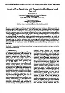
Abstract: Implementation of Real-time adaptive noise cancellation for strongly corrupted speech signal using the TMS3206713 DSP starter kit (DSK) is achieved. LMS algorithm is used for adaptation. The program code for the system is created in a MATLAB Simulink environment. The model is converted from MATLAB to DSP kit through Code Composer Studio which is an integrated development environment for TI’s digital signal processors. The analog input channel of the DSK is adjusted so as to satisfy the requirement of having two inputs for the adaptive noise canceller. The LMS parameters are chosen to give higher performance and improvement in signal to noise ratio of 4dB is obtained. I. INTRODUCTION Speech is a very basic way for humans to convey information to one another with a bandwidth of only 4 kHz; speech can convey information with the emotion of a human voice. The speech signal has certain properties: It is a one-dimensional signal, with time as its independent variable, it is random in nature, it is nonstationary, i.e. the frequency spectrum is not constant in time. High-frequency noise masks only the consonants, and its effectiveness as a mask decreases as the noise gets louder. But low-frequency noise is a much more effective mask when the noise is louder than the speech signal, and at high sound pressure levels it masks both vowels and consonants. [1]. Adaptive filters are employed because they are environmentally self adjusting systems which allow to solve random problem processes. Among all adaptive algorithms, Widrow and Hoff's least mean square (LMS) has probably become the most popular for its robustness, good tracking capabilities and simplicity, both in terms of computational load and easiness of implementation; it requires only a finite-impulse response implementation; therefore, been successfully applied to a wide variety of using the steepest descent method. II. RELATED WORKS Different applications of the adaptive digital filters were studied as early as the 1950s. Now adaptive filters are ubiquitous tools for numerous real-world scientific and industrial applications. The initial works on adaptive echo cancellers started around 1965. It appears
Mosharaka for Researches and Studies (16C-142) 978-0-9836521-1-3
that Kelly of Bell Telephone Laboratories was the first to propose the use of an adaptive filter for echo cancellation, with the speech signal itself utilized in performing the adaptation [2]-[3]. Performance of adaptive filtering algorithms as a comparative study is introduced by Yuu-Seng Lau, Zahir M.Hussian and Richard Harris [4]. The Performance of an adaptive noise canceller with DSP processor is studied in [5]. [6] discussed the real time implementation of adaptive noise cancellation based on an improved adaptive wiener filter on Texas Instruments TMS320C6713 DSK; its performance is compared with the Lee’s adaptive wiener filter. Noise suppression in speech signals using adaptive algorithms is presented by [7]. The problem of controlling the noise level has become the focus of a tremendous amount of research over the years; paper [8] compared the performance of many adaptive algorithms in noise cancellation. III. LMS ALGORITHM Because the exact measurements of the gradient vector are not possible and since that would require prior knowledge of both the correlation matrix R of the tap inputs and the cross correlation vector p between the tap inputs and the desired response, the optimum wiener solution could not be reached. Consequently, the gradient vector must be estimated from the available data when operating in an unknown environment. After estimating the gradient vector we get a relation by which the tap weight vector can be updated recursively as: W (n+1) = w (n) + μ u(n) [d*(n) - u`(n) w(n)] Where μ = step size parameter u`(n) = hermit an of the matrix u d*(n) = complex conjugate of d(n) Eventually we may write the result in the form of three basic relations as follows: 1. Filter output: y (n) = w (n) u (n). . . . . . . (1 ) 2. Estimation error or error signal: e (n) = d (n) – y (n) . . . . . .(2 ) 3. Tap weight adaptation: w (n+1) = w (n) + μ u (n) e* ( n) . . . .(3 ) Equations 1&2 define the estimation error e(n), the computation of which is based on the current estimate of the tap weight vector, w(n). .Note that the second term, μ u(n) e*(n), on the right hand side of equation
28
Mosharaka International Conference on Communications, Computers and Applications
MIC-CCA2011
represents the adjustments that is applied to the current estimate of the tap weight vector, w (n). The iterative procedure is started with an initial guess w(0). The algorithm described by equations 1and 3 is the complex form of the adaptive least mean square algorithm. At each iteration or time update, this algorithm requires knowledge of the family of stochastic gradient algorithms. In particular, when the LMS algorithm operates on stochastic inputs, the allowed set of directions along which one “step” from one iteration to the next is quite random and therefore cannot be thought of as consisting of true gradient directions.
automatically adjusts its own impulse response through a least squares algorithm such as LMS that responds to an error signal dependent, among another things, on the filter's output. Thus with the proper algorithm, the filter can operate under changing conditions and can readjust itself continuously to minimize the error signal. It can be seen that the error signal used in an adaptive process depends on the nature of the application. In noise canceling systems the practical objective is to produce a system output, s + n0 - y, that are a best fit in the least squares sense to the signal s. This objective is accomplished by feeding the system output back to the adaptive filter and adjusting the filter through an adaptive algorithm to minimize the total system output power.
Figure 1: A detailed description of the LMS adaptive filter
Assuming that s, n0, n1, and y are statistically stationary and have zero means. Assume that s is uncorrelated with n0 and n1, and suppose that n1 is correlated with n0. The output is e = s + n0 – y .. .(4) Squaring, one obtains e²=s²+ (n0–y)² + 2s (n0–y) . . . . . (5) Taking expectations of both sides of (2), and realizing that s is uncorrelated with n0 and with y, yields E[e²] = E[s²] + E[(n0 – y)²] + 2E[s(n0 - y)] =E [s²] +E [(n0 - y) ²] . . . . . . (6) The signal power E [s²] will be unaffected as the filter is adjusted to minimize E [e²] accordingly, the minimum output power is: Emin [e²] =E [s²] +Emin [(n0—y) ²] . . . . . (7) When the filter is adjusted so that E [e²] is minimized, E [(n0-y) ²] is therefore also minimized. The filter out put y is then a best least squares estimate of the primary noise n0. Moreover, when E (n0 - y)²] is minimized , E[(e - s)²] is also reference input . (e - s) = (n0 - y) . . . . (8) Adjusting or adapting the filter to minimize the total output power is thus tantamount to causing the output e to be a best least -squares estimate of the signal s for the given structure and adjustability of the adaptive filter and for the given reference input. The output e will generally contain the signal s plus some noise. From (4), the output noise is given by (n0-y). Since minimizing the output noise power and, since the signal in the output remains constant, minimizing the total output power
Figure 2: Adaptive Noise Canceller
IV. NOISE CANCELLATION The basic noise-canceling situation is illustrated in figure 2. A signal is transmitted over a channel to a sensor that receives the signal plus an uncorrelated noise n0. The combined signal and noise, s + n0, form the "primary input" to the canceller. A second sensor receives a noise n1, which is uncorrelated with the signal but correlated in some unknown way with the noise n0. This sensor provides the "reference input” to the canceller. The noise n1 is filtered to produce an output y that is a close replica of n0. This output is subtracted from the primary input s+ n0 to produce the system output, s + n0 - y. If the characteristics of the channels over which the noise was transmitted to the primary and reference sensors are known, one could, in general, design a fixed filter capable of changing n1 into y= n0. The filter out put could then be subtracted from the primary input, and the system output would be the signal alone. Since, however, the characteristics of the transmission paths are assumed to be unknown or known only approximately and not of a fixed nature, the use of a fixed filter is not feasible. Moreover, even if a fixed filter are feasible, its characteristics would have to be adjusted with a precision difficult to attain, and the slightest error could result in increased output noise power. In the system shown in figure 2, the reference input is processed by an adaptive filter that
Mosharaka for Researches and Studies (16C-142) 978-0-9836521-1-3
29
Mosharaka International Conference on Communications, Computers and Applications
MIC-CCA2011
maximizes the output signal-to-noise ratio. It can be seen from (6) that the smallest possible output power is Emin [e²] = E[s²].When this is achievable ,E[(n0-y)²] = 0. Therefore, y = n0 and e = s. In this case, minimizing output power causes the output signal to be perfectly free of noise. V. IMPLEMENTATION The Texas Instrument's DSP starter kit (DSK) TMS320C6713 is used to implement the LMS algorithm. The DSK board includes the C6713 floatingpoint digital signal processor, a 32-bit stereo codec TLV320AIC23 for input and output, 16MB of synchronous dynamic random access memory (SDRAM), 256KB of flash memory and two 80pin connectors for external peripheral and external memory interfaces . The C6713 operates at 225 MHz and delivers up to 1350 million floating-point operations per second (MFLOPS), 1800 million instructions per second (MIPS) and 450 million multiply-accumulate operations per second (MMACS). Figure 3 (a) and (b) shows the TMS320c6713 based DSK board and diagram respectively [9].
Figure 4: Implementation procedure from the Simulink model to the target DSP.
The DSP board has a single line-in input stereo channel, so we separate this channel into two mono channels to be used as primary input and reference input to the noise canceller. The input signal(primary input) is fed through a wide sense microphone to the DSK board. The reference input is fed to DSK board through a second microphone. In this way the signals are fed to the 6713 DSP as shown in figure 5. The two channels is a 16bit monaural audio signal with a sampling frequency of 8KHZ. The noise signal is generated by the Matlab software and is applied to stereo speaker ..
Figure 5: Implementation Model
Figure 3: TMS320C6713 based DSK board and diagram
The program code for the real system is made in a MATLAB Simulink environment. The Code Composer Studio is used to convert the model from MATLAB to DSP. Simulink and Code Composer studio are connected to each other with MATLAB’s Link. Block diagram in figure 4 illustrates the implementation procedure generally used [10].
Mosharaka for Researches and Studies (16C-142) 978-0-9836521-1-3
VI. EXPERIMENTAL RESULTS LMS Noise cancellation for Speech Signal Processing needs a high performance processor including an arithmetic floating point. In this section we test the performance of the LMS algorithm for noise cancellation. The LMS algorithm parameters have been chosen to introduce a higher performance. the parameters is set to the step size factor μ (μ = 0.0032) and the filter length N (N=32). The phrase "Bism Allah Alrahman Alrahem" is used as the speech signal. Figure 6 displays the time series input signal. It can be observed that the input signal is
30
Mosharaka International Conference on Communications, Computers and Applications
MIC-CCA2011
strongly corrupted (low S/N ratio) by the noise shown in figures 7 and 8 in time and frequency domains respectively.
Figure 9: Output of noise canceller
Figure 6: Corrupted signal
Figure 10: Speech Signal before and after noise cancellation
Figure 7: Noise signal
Figure 11: Welch power spectral estimation of input signal and filtered signal
Figure 8: Welch power spectral estimation of Noise signal
From figure 9, it can be seen that there is a considerable improvement in the output signal. Figures 10 and 11 assures the noise reduction taking place at the output. The amount of this reduction is measured to be 4 dB.
Mosharaka for Researches and Studies (16C-142) 978-0-9836521-1-3
VII. CONCLUSIONS The TMS320C6713 DSP kit is hardwarely and softwarely configured to implement real-time adaptive speech signal processing as adaptive noise canceller. This includes the Matlab program interfacing with the DSK hardware and the modification in the analog input channel (line-in) so as to acquire the two inputs necessary for adaptive noise cancellation. One high sensitive microphone is connected to the primary input (s + no ), and the other is low sensitive microphone connected as a reference input (n1) to overcome the speech distortion problem . LMS algorithm is used in the adaptation process. The input speech signal is strongly corrupted with a noise signal and a considerable real-time noise reduction (up to 4dB) is obtained.
31
Mosharaka International Conference on Communications, Computers and Applications
References [I] Vijakumar, V. and Vanathi, P., “Modified Adaptive Filtering Algorithm for Noise Cancellation in Speech Signals”, Electronics and Electrical Engineering -Kaunas: Technologija, 2007. [2] Lilatul Ferdouse1, and et. al. " Simulation and Performance Analysis of Adaptive Filtering Algorithms in Noise Cancellation "; IJCSI International Journal of Computer Science Issues, Vol. 8, Issue 1, January 2011. [3]
MIC-CCA2011
[9] Texas Instruments,"TMS320C6713 DSK Technical Reference", SPECTRUM Digital Inc., November 2003. [10] Antti Lankila,” Simulation Model for an Active Noise Control System Development and Validation”, Master’s Thesis, Helsinki university of Technology, Faculty of Electronics, Communications and Automation, Espoo, February 18, 2008.
B.widrow and S.D.Stearns, adaptive Signal Processing, Englewood Cliffs, NJ:Prentice-Hall. 1985, p.474 .
[4] Yuu-Seng Lau, Zahir M.Hussian and Richard Harris,“Performance of Adaptive Filtering Algorithms:A Comparative Study”, Austrailan Telecomminications ,networks and Applications Conference(ATNAC), Melbourne, 2003. [5] Boo-Shik Ryu, Jae-Kyun Lee, Joonwan Kim', ChaeWook Lee,"The performance of an adaptive noise canceller with DSP processor", 40th Southeastern Symposium on System Theory, University of New Orleans New Orleans, LA, USA, March 16-18, 2008. [6] Gaurav Saxena, Subramaniam Ganesan, and Manohar Das "Real time implementation of adaptive noise cancellation", IEEE International Conference on Electro/Information Technology, EIT2008, AmesIA, 2008. [7] V.JaganNaveen, T.prabakar, J.Venkata Suman , P.Devi Pradeep ; "NOISE SUPPRESSION IN SPEECH SIGNALS USING ADAPTIVE ALGORITHMS "; International Journal of Signal Processing, Image Processing and Pattern Recognition, Vol. 3, No. 3, September, 2010. [8] Raj Kumar Thenua et. al., "Simulation and Performance Analysis of Adaptive Filter in Noise Cancellation", International Journal of Engineering Science and Technology, Vol.2(9), 2010, 4373-4378 .
Mosharaka for Researches and Studies (16C-142) 978-0-9836521-1-3
32