International Conference on Artificial Reality & Tele-existence ICAT'97; Tokyo, Dec. 3-5, 1997. Real World .... and the remote environment to enable it to achieve the goal state by ..... call up views from special locations like the manipulator ...
Proc. International Conference on Artificial Reality & Tele-existence ICAT'97; Tokyo, Dec. 3-5, 1997
Real World Teleoperation via Virtual Environment Modelling Paul Milgram Mechanical & Industrial Engineering Dept. University of Toronto Toronto, Ontario, Canada &
John Ballantyne Spar Aerospace Limited Brampton, Ontario, Canada Abstract The fields of artificial reality and conventional telerobotics share many common technological challenges. In this paper we discuss the concept of applying techniques of virtual environment simulation to address some of the challenges of remote manipulation of teleoperated systems in unstructured environments, with a focus on remote excavation. We first present a taxonomy of factors for distinguishing between some of the constraints imposed by different remote interaction environments. In contrast to the conventional methods of continuous closed loop manual control of remote systems, we discuss the concept of supervisory control. This leads to the notion of elevating the operator from low level tasks by providing a virtual model of the remote work site, to allow the operator to plan and rehearse remote operations off-line prior to execution. In an attempt to reduce this concept to practice, we review two complementary approaches: Augmented Reality TEleManipulation Interface System (ARTEMIS) and Virtual Environment for Remote Operations (VERO).
1. Introduction Until recently advances in the fields of Telerobotics and Artificial Reality have occurred essentially independently of each other. In general, Telerobotics is
Interaction Environment
Mental Model =>Telepresence Experience
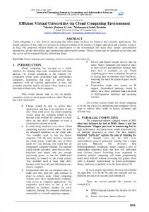
dedicated largely to challenges as diverse as remote mining, orbital construction, planetary exploration, telesurgery, underwater pipeline inspection and the handling of nuclear materials in inaccessible radioactive reactor vessels, while Artificial Reality is dedicated essentially to the creation of compelling virtual environments within which human participants are led to feel somehow present, for purposes such as training, design evaluation and entertainment. Both situations nevertheless share the common structure of a human participant “tele-existing” within some kind of an artificial interaction environment. This concept is illustrated in the schematic diagram shown in Fig. 1. In the Telerobotics case on the left, the interaction environment is ordinarily real, and the human participant experiences some degree of "telepresence", or the sense of being physically present and, through some kind of remote manipulator, interacting with real objects at the remote teleoperator site. In the Artificial Reality case on the right no real remote environment need exist, but, although the entire interaction environment is simulated, or virtual, the operator nevertheless experiences a similar sense of being physically present and interacting with the virtual objects via visual, auditory or force displays. (Sheridan, 1992a).
Interaction Environment
Mental Model =>Telepresence Experience
Commands
Commands
Human Participant
(a)
Interaction Environment (REAL)
Human Participant
(b)
Feedback
Feedback
(Video)
(CGÎ)
Interaction Environment (VIRTUAL)
Fig. 1 Generic representation of telepresence: a) Telerobotics: Human participant experiences interaction of remote manipulator with real environmental objects; b) Artificial Reality: Human participant experiences interaction with computer simulation of both manipulator and environmental objects.
Proc. International Conference on Artificial Reality & Tele-existence ICAT'97; Tokyo, Dec. 3-5, 1997
Distinguishing Factor Extent of World Knowledge Degree of Worksite Structure Degree of Worksite Constancy Degree of Mechanical Dexterity Degree of Operational Criticality
General Definition / Description Extent of (prior) quantitative data about environment and objects contained within it. Is the worksite "orderly", and thus easily describable, or is it arbitrary and featureless? Is the environment relatively static, or are there changes which occur independently of the prescribed work activity? Does prescribed work involve complex motions, controlled contact, simultaneous coordination of several objects, etc.? Are consequences of imperfect performance tolerable?
"Low End" Examples No prior knowledge; first visit to worksite. Topologically uneven worksite, littered with unknown objects: e.g. rocks, rubble.... Locomotion: remote vehicle moves (relatively rapidly) through worksite; frequent changes of viewpoint Impact shovelling at rock face; remote inspection.
Compliant manipulator; no suspected hazards.
"High End" Examples Known (man-made) worksite; dimensions contained in CAD system. Worksite comprises known objects, with rectangular walls, floors, tables, etc. Static or slowly changing scene; no viewpoint change; no locomotion Delicate probing, placement and/or insertion tasks.
Presence of toxic substances; possibility of mortal danger.
Table 1: Distinguishing properties of remote interaction environments With the advent of publications such as Presence (the journal of Teleoperators and Virtual Environments) and of conferences such as ICAT, however, it is now well accepted that the two fields of endeavour share not only common technological challenges but also similar issues related to user metaphors and human interface design. As indicated in Fig. 1, the human participant in either case must develop a mental model of the environment with which s/he is interacting, thus leading to some kind of telepresence experience. The objective of the present paper is to outline some of the concepts underlying our current development of a
Distinguishing Factor Extent of World Knowledge Degree of Worksite Structure Degree of Worksite Constancy Degree of Mechanical Dexterity Degree of Operational Criticality
Virtual Environment system for Remote Operations (VERO) (Ballantyne et al, 1997) . In particular, our efforts are centred on remotely controlled excavation systems, for applications in areas such as toxic waste removal and mining.
2. Distinctions in Defining Remote Interaction Environments Prior to discussing our design philosophy, it is important first to clarify some of the constraints which typically drive the design of teleoperator systems in
Buried Waste Removal (Remote Excavation)
Sample Application Space Station Orbital Replacement Unit (ORU) Exchange
Robotically Assisted Minimally Invasive Surgery
Low
High
Medium
Low
High
Low / Medium
Medium
High
Low / Medium
Medium / High
Medium
High
Medium / High
High
High
Table 2: Application of Table 1 taxonomy to three teleoperation cases
-2-
Proc. International Conference on Artificial Reality & Tele-existence ICAT'97; Tokyo, Dec. 3-5, 1997
general. For that purpose we present Table 1, in which five key factors are proposed as a means of distinguishing among different operational situations and environmental circumstances. Needless to say, this list is not exhaustive, and other factors could easily be added. The objective of such a classification scheme is to provide a framework for categorising research and development efforts, by enabling different researchers to be explicit about the definition of the particular problems that they are addressing. An example of how this taxonomy is used for framing research on various control strategies, for instance, is given in Section 3. To facilitate the discussion we present Table 2, in which we briefly analyse three examples of specific remote operation situations in terms of the Table 1 taxonomy presented. Our current focus of interest, Remote Excavation, is shown in the first column.
ARTEMIS
Fig. 3. Degree of Autonomy taxonomy The conventional case of Manual (Master/Slave) Teleoperation at the low end of the spectrum is the simplest and most direct. In this case, the human operator (HO) remains continuously in the control loop. Unfortunately, a number of disadvantages accompany this simplest case. For example, due to inevitable restrictions in the field of view of the remote camera(s) and in the quality of the visual displays fed back from the remote worksite, the HO is often unable to maintain a level of situational awareness sufficient for safe and efficient task execution. Furthermore, restrictions in communication due to, for example, limited channel capacity and transport delays, can result in awkward and often unstable control performance. In addition, because active control of the remote system stops whenever the loop becomes open, the need for the HO to remain in the control loop can lead to fatigue and other forms of operator stress.
Remote World Fully Modelled
(C o n t i n u u m)
VERO
Manual Teleoperation
Although in Table 1 we present examples of both low and high end cases, it is important to note that, as discussed elsewhere (e.g. Milgram et al, 1994a, 1994b, 1995), each factor listed should best be regarded as a continuum, rather than a simple dichotomy, with actual real-world cases lying somewhere between the extrema indicated. An example of one of the Table 1 factors, Extent of World Knowledge is presented in Fig. 2.
Extent of World Knowledge
Supervisory Control
(C o n t i n u u m)
Degree of Autonomy
Autonomous Robotics
VERO
ARGOS: VTM The concept of Supervisory Control of telerobotic systems was introduced by Sheridan and colleagues approximately 30 years ago (Ferrell & Sheridan, 1967), as a means of addressing some of the problems outlined above. A thorough treatment of the concept, together with a review of associated research, can be found in Sheridan (1992b). The essence of the Supervisory Control concept is that the HO is elevated from the low level task of continuous closed loop control and instead is provided the means of communicating higher level goal states to the teleoperated system, together with guidelines, as necessary, for arriving at those goal states. The remote subordinate control system in the meantime is equipped with sufficient means for sensing and measuring variables generated by both the machine and the remote environment to enable it to achieve the goal state by performing a variety of prescribed functions autonomously.
Remote World Completely Unknown Fig. 2: Extent of World Knowledge taxonomy.
3. Supervisory Remote Control The block diagram shown in Fig. 1 depicts the generic case of a human interacting with a remote environment; however, we must recognise that in actuality a variety of possible modes of interaction exist. These too can be classified in many ways, one of which is by invoking yet another continuum, this time in terms of the degree of autonomy granted to non-human elements in the system. Fig. 3 illustrates this concept. (See Milgram et al, 1995, for further details.)
-3-
Proc. International Conference on Artificial Reality & Tele-existence ICAT'97; Tokyo, Dec. 3-5, 1997
Several variations of this basic concept have been proposed over the years, including supervised autonomy (Burtnyk & Greenspan, 1991), virtual telerobotic control (Zhai & Milgram, 1991, 1992), point-and-direct control (Cannon & Thomas, 1997) and the set director model (Ballantyne et al, 1997). It is noteworthy that, in graduating from low level control tasks to become a human supervisor (HS), each of these schemes acts in a sense to reduce the degree of telepresence, since the HS no longer needs to be as intimately involved with moment to moment control functions.
example, to include physical and mechanical properties of the robot-environment interface. • Degree of Operational Criticality: High levels of this factor will increase the need for being able explicitly to designate particular areas and define specific boundary areas.
4. Model Based Telerobotic Control In this section we present an overview of our current efforts to address many of the above mentioned issues associated with teleoperation in unstructured environments. In Section 4.1 we summarise the capabilities of ARTEMIS (Augmented Reality TEleManipulation Interface S ystem) and following that the VERO (Virtual Environments for Remote Operations) system. Further details about ARTEMIS may be found in (Rastogi et al, 1996 and Milgram et al, 1997). Further details about the VERO project (Virtual Environments for Remote Operations) may be found in (Ballantyne et al, 1997).
It is also important to note that, in order for the HS to be able to relay task related instructions about particular objects or locations at the remote site, there is a paramount need to be able to communicate explicit quantitative information about things such as particular objects and/or absolute object locations, in 3D realworld coordinates. What is thus needed for essentially any level of supervisory teleoperation control, in other words, is some kind of a model of the remote environment and of the remote manipulators. For instance, in order to convey any kind of a "put that there" or "dig there" command, it is clearly necessary to know in advance or determine on-line where "there" is. In manual master/slave teleoperation, more often than not, ones only option is to drive to "there" or move the manipulator until "there" has been reached. With supervisory control, on the other hand, the potential exists to convey this in other ways. At high levels of autonomy (Fig. 3), with the support of computational vision, it should be possible simply to specify the object – e.g. "pick up the hammer". At lower levels, however, it is more important to convey where the hammer is than the knowledge that what is about to be picked up is in fact a hammer.
The basic long-term philosophy underlying both designs is that remote operations are likely to be more productive and less tedious if the human operator (HO) can be taken out of the conventional continuous manual control loop shown in Fig. 1a and be transformed instead into a Human Supervisory (HS) controller. As discussed above, this can not easily be accomplished without an adequate amount of world knowledge. In general, the higher the degree of world knowledge available, the higher the level of supervisory control that can in principle be achieved. This principle is illustrated in Fig.’s 2 and 3. In the former we note that the ARGOS Virtual Tape Measure (VTM), summarised in Section 4.1, can be used to elevate world knowledge from the lowest level, “remote world completely unknown”. The VERO system, which is based on the same principle of continual updating and refinement of its modelling database, is capable of reaching higher levels of quantitative world knowledge, as shown in Fig. 2. Fig. 3 echoes this relationship by indicating VERO above ARTEMIS (the telemanipulation system based on ARGOS) on the Supervisory Control continuum.
Referring now to Tables 1 and 2, it should become apparent why the factors listed there have been selected as critical distinguishing properties for remote interaction environments (in particular remote excavation) and how each of them relate to the important concept of world modelling: • Extent of World Knowledge: If this is very high, for example, there is little need to acquire additional information and one can easily plan operations offline using the model alone. • Degree of Worksite Structure: If this is high, the task of modelling the worksite will ordinarily be much easier than if the degree of structure is low. • Degree of Worksite Constancy: If this is low, frequent updates to the model will be necessary. • Degree of Mechanical Dexterity: If this is high, for example, then dynamic control of the manipulator will be more prone to error. In addition, a more intricate model of the worksite will be necessary, for
4 . 1 ARTEMIS: Augmented Reality TEleManipulation Interface System The ARTEMIS concept represents a further development of the ARGOS (Augmented Reality through Graphic Overlays on Stereo-video) technology, which has been reported on extensively (e.g. Drascic & Milgram, 1991; Milgram et al, 1994a, 1994b, 1995, 1997a). As the name implies, ARGOS permits one to view an (unmodelled) video scene and to superimpose on it computer generated stereoscopic graphic images.
-4-
Proc. International Conference on Artificial Reality & Tele-existence ICAT'97; Tokyo, Dec. 3-5, 1997
4.1.1 ARGOS Toolkit There are three primary purposes for applying the ARGOS toolkit to telerobotic operations: 1) for probing the real remote environment visible on video, 2) for enhancing video images through real object overlays, thus compensating for image degradation due to occlusion of objects, poor video quality and bad lighting conditions, and 3) for introducing realistic looking but non-existent graphic objects, so that they may appear to be a part of the video scene. Bearing this in mind, the tools provided by ARGOS can be classified as "probing tools" or "enhancement tools": • The fundamental probing tool is the virtual pointer, a stereo-graphic cursor which can be positioned anywhere in the stereo video scene [Drascic & Milgram, 1991]. When properly calibrated, the virtual pointer gives a direct readout of its corresponding {x,y,z} location in absolute real world units, and thus quantifies the 3D location of any object adjacent to which it is placed. • The virtual tape measure (VTM), an extension of the virtual pointer, is used for measuring distances between points in the remote stereo video scene. It is generated by clicking a start point with the virtual pointer and dragging a virtual line of calibrated length through the video image to a selected end point. A recent enhancement of the VTM has produced a computer-assisted VTM, based on interactive use of a set of computational vision tools. This allows the user to request an alternative version of the actual 3D location of the virtual SG pointer relative to a designated real SV object. The user is then free to accept the machine version, remain with her own original perceptual estimate or, ideally, to confirm agreement of the two estimates. • Virtual landmarks are graphical objects of known length, or known separation, superimposed on the video scene to enhance the HO's ability to judge absolute distances, and thus the absolute scale of the remote world. • Virtual planes are generated by specifying three or more coplanar points with the virtual pointer. One important application of such planes is for restricting 3D movements of simulated or real objects within a 3D real-world video scene. • Virtual objects, which are either interactively generated or premodelled according to particular geometric specifications, can be superimposed on stereo video at designated locations and at specified orientations to appear as if they are really present within the remote scene. • Virtual encapsulators are wireframe shapes created on the remote stereovideo scene to encapsulate real objects. This can be done approximately, as a tool for indicating an envelope of size, position and orientation of a real object in space, or more exactly, for highlighting the edges of an object. Virtual
encapsulators require the same modelling, location and orientation data as do virtual objects. • Virtual trajectories are graphical indications of prescribed robot motions, added to the image of the real robot at a particular initial configuration, to specify the desired trajectory for the robot to follow. These can be used, for example, for path planning purposes, by placing trajectories into the video space and verifying plans for their accuracy in relation to the actual (unmodelled) worksite. 4.1.2 Recent ARGOS Performance Data Recent studies to evaluate the precision and accuracy of the VTM have generated very promising results. As reported in (Milgram et al, 1997a,b), measurements made on a series of targets of separation along the order of 25 cm produced a small but significant overestimation bias of 0.6 cm. In general the results indicated achievable accuracies of 3-5%. In terms of precision, it was found that there was a significant improvement in standard deviation of the computer assisted VTM over the unassisted version. This finding supports the design objective of providing a more reliable probing tool for remote operations. In another recent study (Kim et al, 1997) have evaluated the VTM as an intra-operative tool for micro(neuro)surgery. Data from their precision and accuracy studies have concurred with results from the earlier studies, with indicated errors along the order of millimetres in a microscopic (x16 magnification) environment. 4.1.3 Virtual Telerobotic Control As an extension of the ARGOS toolkit, a model based virtual telerobotic control system, ARTEMIS, has been developed. The remote manipulator situated in the real unstructured, unmodelled world is sensed by video and reproduced locally for the HO. Superimposed upon that video view is a fully controllable stereographic 3D model of the HO’s own robot, that is, a virtual manipulator. Using the ARGOS augmented reality toolkit, primarily the VTM, the HO is able interactively to build up a partial model of the remote world, on the basis of which commands intended for the real remote system can be formulated, rehearsed and ultimately transmitted to the remote site. Because it is often impossible to update the video image from the remote site on a continuous basis, ARTEMIS grabs a single stereo video image transmitted from the remote scene and the operator then uses the local computer to model the remote site, as outlined above. Note that such local off-line control is essentially closed loop, since there is no time delay due to communication with the remote site. Once an offline programmed manoeuvre has been approved, the
-5-
Proc. International Conference on Artificial Reality & Tele-existence ICAT'97; Tokyo, Dec. 3-5, 1997
operator simply relays the trajectory end point and robot control signals for execution at the remote site. Because the information transmitted at this point requires a very low bandwidth, subsequent execution of the manoeuvre at the remote site can commence effectively instantaneously. ARTEMIS has been tested by successfully controlling our robot at the University of Toronto from several locations around the world, the most distant being from Kyoto, Japan.
presents a formidable challenge for construction of the virtual environment shown in Fig. 4. One of the factors motivating our project is that unfortunately few if any of the commercially available robot graphic simulation packages are able to link interactive 3D graphic modelling capabilities to real-world sources. Furthermore, since it is of critical importance that the virtual graphic workspace model correspond to the real worksite to the extent that it is necessary to support required operations, we have formalised the additional requirement that VERO graphic models be updated as rapidly as possible as operations progress.
4.2 VERO: Virtual Environments for Remote Operations The aim of the VERO system is very similar to ARTEMIS. VERO accomplishes this aim, however, by providing a much more detailed virtual model of the remote real world interaction environment, as indicated in Fig. 2. This model is modified with real-world imaging updates, which allows the HS to perform high level supervisory functions outside of the primary control loop. The current state of VERO is illustrated in Fig. 4, which differs from Fig. 1a through the addition of a Virtual Environment model proximal to the HS. Note also that, whereas the loops joining the HO and the remote system in Fig. 1 are depicted as solid lines, signifying continuous communication, in Fig. 4 these links are intermittent. The HS is now able to concentrate on the principal high level supervisory functions of Planning, Teaching, Monitoring, Intervening and Learning (Sheridan, 1992b) rather than only continuous control.
4.2.1 Worksite Capture and Representation In its present form VERO incorporates the following methods of acquiring quantitative data about the remote worksite, for construction and presentation of the virtual workspace: • Remote range imaging data. The principal source of range imaging data is the NRCC 3D laser range scanning system (Greenspan et al, 1995). Data sets produced by this system can be displayed as clusters of 3D points, and are usually readily interpreted as images by the human viewer, especially if the viewpoint is dynamically adjustable. When the individual points of the data set are rendered with the grayscale values corresponding to their measured intensity (reflectance), the visual interpretation is even clearer. However, due to the high computational costs of this approach, such point sets are generally not used for data display. Rather, surface representations are employed, because these are less expensive computationally, because they provide a normal vector at every surface location (which point sets do not), thereby enabling artificial lighting models, and because they readily afford visual navigation, such as zooming in, which is not the case with point sets (which will spread apart when
As indicated in Table 2, remote excavation, currently our primary target application, is characterised by an absence of prior CAD models, very little worksite structure and a medium level of worksite constancy, and demands as well a fairly high level of mechanical dexterity for operations which have typically a mediumhigh level of criticality. This combination clearly
Plan, Teach, Monitor, Intervene, Learn
Commands (Intermittent)
Human Supervisor (HS)
Virtual Environment
Interaction Environment
Feedback (Intermittent)
Fig. 4: VERO Model based teleoperation schematic
-6-
Proc. International Conference on Artificial Reality & Tele-existence ICAT'97; Tokyo, Dec. 3-5, 1997
approached.) • Other range imaging data. VERO is also able to import and display other kinds of range data. In particular this includes digital terrain maps collected from aerial surveys. Since these data tend to involve very large files, due to the areas covered and the resolution of the data sets, and since these data are typically not ordered on a regular grid in the same way that the laser range data are, integrating the two sources has been a major challenge. • Sparse range data. Because it is often sufficient to measure the 3D locations of a small number of points at the worksite, to create a model of one object or a few key landmarks, such as the locations of a set of excavation area markers, VERO software includes a simple interface for entering theodolite survey data, a common form of 3D point measurement. • Sparse CAD object models. The VERO software can also import and display 3D CAD models of objects such as scene props, virtual barriers and 3D stencils. Machine models are created from collections of parts for which the relative positions are determined through appropriate kinematic relationships. (The VERO software does not itself contain CAD modelling tools as such.) • Scalar data fusion. The 3D models and surfaced range images in VERO can be used as geometric templates to support the display of other data being measured, such as temperature, pressure, etc. Usually, such physical measurements correspond to particular locations in 3D space, but the measurements do not explicitly include those location data. These must instead be inferred from the known or estimated positions of the sensor and other local objects at the time the sensors are sampled. An example of this is radiation sensor data, collected as a series of readings made at several placements and orientations of a collimated sensor probe. By knowing the probe characteristics, and the position and direction of the probe with respect to the surface that contains the radioactive material, an estimate of the radioactivity level at the surface of the objects being monitored may be calculated. Other measurements which may be treated this way include eddy-current signatures for metal surface inspection, temperature readings and coating thickness. • Measured machine states. Another source of data fusion comes from the remote machines, which typically have a variety of internal sensors that are used to measure and report current states (typically positions, joint angles, tilt angles, velocities, accelerations and forces). These signals are relayed to VERO as a real-time data stream. • Estimated machine states. Often it is not possible to measure all of the remote machine states accurately, in a timely manner. The VERO software therefore
employs simple kinematic models to estimate machine position and pose based on control inputs. This capability is especially required during “rehearsal mode”, when the actual machine is not being driven, but the operator wants to review predicted control actions within the virtual VERO workspace. 4.2.2 World Model Referencing and Updating Prior to using the VERO software for planning, rehearsal or on-line control of a telerobotic task, the virtual machine must be properly situated in the virtual workspace, that is, its base reference frame must be positioned correctly with respect to the workspace frame. The accuracy of this virtual/real correspondence can be quite critical in some applications. (We typically assume that the joint positions correctly correspond to those of the actual machine, since its internal sensors would be calibrated.) In mobile robotics applications it is common practice to use external sensing systems, such as RF beacons, optical tracking, GPS, etc., to report the robot position in the workspace. However, in the VERO project, we have attempted to use only range imagery to ascertain the position of the remote machine in its environment. The following camera mounting cases may be encountered: • The range imaging camera is mounted to the remote machine. In principle, in this most common case, since one always knows the position of the camera frame with respect to the mobile base, any changes in vehicle position can be determined by observing apparent movement in fixed landmarks. The operator would construct a reference frame for the virtual environment by selecting three or more well spaced and non-colinear landmarks from the environment scans. • The range imaging camera is mounted to a second mobile platform. Sometimes it is advantageous to use a second, independent, platform to carry the range imaging camera, or even to simply mount the camera in one fixed location in the workspace. In either case we assume that it is possible to set up the camera so that some views include a portion of the work vehicle. The operator would select features within the range image set to construct two reference frames: one for the vehicle and another for the environment. The operator would therefore need to ensure that both frames were updated in the virtual workspace according to the latest range images received from the remote workspace. • The range imaging camera is fixed in the environment frame. The VERO software includes features designed to simplify the task of repositioning objects and point data sets in the virtual environment. The operator simply identifies a “destination” feature by eye and uses the mouse to
-7-
Proc. International Conference on Artificial Reality & Tele-existence ICAT'97; Tokyo, Dec. 3-5, 1997
select and mark it. The corresponding “source” feature is similarly selected. Once all the feature pairs have been selected, the objects are automatically repositioned. The operator interaction is the same whether the source and destination objects are point data sets, models, or one of each type.
occur fairly rapidly, producing a visual impression of digging action. The digging algorithm does not attempt to simulate the resistance of soil to shovel motion, nor does it support transferring and dumping of quantities of soil another locations. • Robots appear to manipulate (grasp, reposition, release) objects which are designated for manipulation by the machine model. In other words, they may be temporarily attached to the end-effector reference frame, repositioned, and then released at the new location. The algorithm does not model contact interaction forces, however, nor does it respect kinematic constraints.
4.2.3 Operator Control Functions The current VERO software allows the operator to effect control actions in a variety of forms. In addition to standard mouse-activated pull-down menus, buttons, sliders, and pop-up forms, we have thus far integrated two 2-axis joysticks with force reflection capability, for remote excavator control. In “dig” mode, left and right hand joysticks are used to control the four axes of the excavator arm (swing, boom, stick, shovel). The force reflection feature is used to indicate to the operator any collision with the virtual barriers mentioned above. Alternatively, at the push of a button the operator can switch to “travel” mode, whereby the joysticks control left and right caterpillar tracks. In this mode the force reflection feature is used to indicate “movement” by simply vibrating the stick. All joystick functions work identically for both “rehearsal” and “live” action modes.
4.2.5 Operator Assistance Features Because the purpose of the VERO software is to assist a human operator/supervisor with the various levels of planning and decision making involved in performing remote operations, a number of features have been provided to make this possible: • Terrain marking, for indicating regions of potential vehicle overturning. • Surface colouring, for indicating location and quantity of non-geometric information, such as temperature, radiation, etc. • Colour Change indication: dynamic changes in object colour to warn of impending overturn, collision, etc. • Virtual Barriers: to “fence off” areas or objects in order to protect against collisions or other intrusions. • 3D Stencils: to constrain teleoperated motions to within pre-defined boundaries. • 3D Tape Measure: to determine straight line distances between any two points within the virtual 3D image. • 3D Protractor: to quickly measure angles between any two intersecting 3D lines.
4.2.4 Physical Simulation Features Due to the computational costs of classical finite methods, the VERO remote workspace models are essentially geometric and kinematic, but do not simulate material properties or dynamic interactions such as forces and accelerations. This decision was made in order to ensure delivery of satisfactorily rapid “real-time” performance at the scale necessary for effective human interaction. Nevertheless, some degree of “natural behaviour” was built in to the environment model as follows (Gagnon et al, 1997): • Vehicles appear to follow the contours of terrain surfaces. The terrain following algorithm allows a virtual vehicle to be driven over a surface such that its height, roll and pitch change to conform to the local surface contour. The algorithm does not account for vehicle suspension or the compressibility of soil, so the behaviour corresponds to a rigid interaction. Moreover, the algorithm does not account for gravity or vehicle centre of mass, so overturning behaviour is not simulated. On the other hand, the terrain following algorithm is rapid and easily meets realtime interactive requirements. • Shovels appear to remove material from the terrain when digging. The digging algorithm takes advantage of a feature of the terraforming algorithm that supports localised and incremental changes to the terrain surface. Usually such changes are affected by the addition of point data sets; however, in the case of digging, the path of the shovel is examined while below the surface boundary and used to generate a revised surface description. The changes to the surface
4.2.6 Display Properties The current VERO software display is a conventional large-screen monitor, comprising a 2D projection of the 3D virtual environment. The projection may be manipulated such that the viewpoint can be smoothly varied, thereby conveying a reasonable sense of depth and space to the user. Another display mode allows for multiple panels to be displayed simultaneously. In this mode, the operator can set up two or more viewpoints (orthographic projections), thus facilitating very precise spatial estimates. The operator can also define a number of “virtual cameras” and activate them through a simple push-button sidebar. This feature allows the operator to call up views from special locations like the manipulator end-link frame. Finally, the VERO software supports a live video feed. The video can be displayed as a separate panel along with one or more virtual view panels. A useful technique is to arrange one of the virtual cameras to have a position and focal length that corresponds to the real video camera. This gives the operator a means to quickly compare the
-8-
Proc. International Conference on Artificial Reality & Tele-existence ICAT'97; Tokyo, Dec. 3-5, 1997
modelled environment with the real world. One important advantage of this facility is if the apparent locations of objects and other modelled features differ between the video view and the virtual view, the operator may then suspect that there has been a modelling error and initiate remedial actions.
6.
7.
5. Tradeoffs and Further Developments
8.
In addition to developing the ARTEMIS and VERO telerobotic control tools independently, we are currently investing efforts to integrate the two concepts as complementary approaches within a single platform. Two of the disadvantages of the laser range imaging approach of VERO, for example, are the high capital cost and the relatively slow update rate. By complementing the VERO system with ARTEMISlike capabilities, we anticipate, for example, being able to replace laser range imaging with video, when cost and/or speed are overriding factors. The price of relying solely on ARTEMIS, however, is a sparser, less flexible model which will not, for example, permit VERO-type variable perspective viewing. Clearly, a viable alternative to both approaches is the use of computational 3D stereo imaging, which is both faster and less expensive than 3D laser range imaging. The disadvantage of the computational stereo option, however, is a much smaller resolution compared to 3D laser range imaging.
9.
10.
11.
12.
13.
In addition to the ARTEMIS/VERO integration effort, we are currently developing the VERO world model building tools further, to facilitate the process of interactive world model updating and re-registration. In addition, we are also developing new work planning and scripting tools, which will permit the off-loading of a greater portion of the low level telerobotic control tasks to the remote control hardware, and thereby further elevate the human's role as a system supervisor..
14.
15. 16.
6. References 1.
2.
3.
4.
5.
17.
Ballantyne J, Greenspan MA, Lipsett M: "Virtual environments for remote operations", ANS 7th Topical Meeting on Robotics & Remote Systems, Augusta, Georgia, 1997a. Drascic D, Milgram P: “Positioning accuracy of a virtual stereographic pointer in a real stereoscopic video world”. Proc SPIE 1457 Stereoscopic Displays and Applications II, 1991. Gagnon E, Greenspan M, Ballantyne J: "Real-time surface following for teleoperation in virtual environments", SPIE Program for Factory, Field and Space. Pittsburgh, Oct. 1997. Greenspan M, Lipsett L, Ballantyne J: Laser range vision for tele-excavation", Robotics & Knowledge -Based Systems Workshop, Montréal, 1995. Burtnyk N, Greenspan M: "Supervised autonomy – partitioning telerobotic responsibilities between
human and machine", International Conf. on Intelligent Teleoperation, Nov, 1991. Cannon DJ, Thomas G: "Virtual tools for supervisory and collaborative control of robots", Presence 6(1), 1997, 1-28. Ferrell WR, Sheridan TB: "Supervisory control of remote manipulation". IEEE Spectrum 4(10) 1967. Kim M, Milgram P, Drake J: “Virtual tape measure for 3D measurements in micro-surgery”. Annual Meeting Human Factors & Ergonomics Soc., Albuquerque, NM, 1997. Milgram P, Takemura H, Utsumi A, Kishino F: "Augmented reality: A class of displays on the reality-virtuality continuum". SPIE Vol. 2351 Telemanipulator & Telepresence Technologies, 1994a, 282-292. Milgram P & Kishino F: "A taxonomy of mixed reality displays". IEICE Trans. Information and Systems, E77-D(12), 1994b, 1321-9. Milgram P, Rastogi A, Grodski JJ: "Telerobotic control using augmented reality". Proc. 4th IEEE Intn’l Workshop Robot & Human Communication (Ro-Man'95), Tokyo, July 1995, 21-29. Milgram P, Yin S, Grodski JJ: “An augmented reality based teleoperation interface for unstructured environments”. ANS 7th Topical Mtg on Robotics & Remote Systems, Augusta, Georgia, 1997a. Milgram P, Drascic D: “Perceptual effects in aligning virtual and real objects in augmented reality displays”. Annual Meeting Human Factors & Ergonomics Soc., Albuquerque, NM, 1997b. Rastogi A, Milgram P, Drascic D, Grodski JJ: “Telerobotic control with stereoscopic augmented reality”. Proc. SPIE Vol. 2653 Stereoscopic Displays and Applications VII & Virtual Reality Systems III, Feb. 1996. Sheridan TB: "Musings on Telepresence and Virtual Presence". Presence, 1(1), 1992a, 120-125. Sheridan TB: Telerobotics, Automation and Human Supervisory Control. MIT Press, 1992b. Zhai S, Milgram P, "Human-robot synergism and virtual telerobotic control", Proc. Annual Meeting of Human Factors Association of Canada, 1992.Zhai S, Milgram P: "A telerobotic virtual control system", Proc. SPIE 1612, Cooperative Intelligent Robotics in Space II, Boston, 1991.
7. Acknowledgements The research reported here has been supported by the Defence and Civil Institute of Environmental Medicine (DCIEM), Manufacturing Research Corp. of Ontario (MRCO), the Institute of Robotics and Intelligent Systems (IRIS), the Natural Sciences and Engineering Research Council (NSERC), the National Research Council of Canada (NRC), AECL Ltd, the Canadian Space Agency, and Precarn Associates.
-9-