Arts et Metiers ParisTech, CNRS, LE2I,. 2 rue T. Dumorey, 71100 ... vertex and faces description of the polygonal mesh of the part. (Figure 3). VHT uses this file ...
Proceedings of the ASME/AFM 2009 of World Conference on Innovative VirtualVR Reality Proceedings the World Conference on Innovative 2009 WINVR2009 Proceedings of the World Conference on InnovativeWINVR09 VR 2009 February 25-26, 2009, 2009, Chalon-sur-Saône, Chalon-sur-Saône, France 25-26 february France WINVR09 February 25-26, 2009, Chalon-sur-Saone, France
WINVR2009-743 WINVR09-743 VIRTUAL ASSEMBLY ENVIRONMENT MODELLING Ulises ZALDIVAR-COLADO Laboratoire d'Ingénierie des Systèmes de Versailles 10 - avenue de l'Europe 78140 VELIZY, France
ABSTRACT In this paper, we present the virtual environment of assembly sequence generation of a product at the design stage. The interaction technique developed for the manipulation of virtual parts includes visual and haptic feedback limited to force sensation in the fingertips and weight and inertia parts sensation. At this stage of development, the parts and subassemblies have kinematics behaviour in the virtual scene. We present some guidelines for modeling a generic virtual environment for performing assembly tasks. Virtual parts modeling and connections modeling is based on characteristics of real parts and connections. The mating phase of assembly is based on the Snap-Fitting technique, which is improved by the addition of vectors in the symmetry axis of virtual parts. An XML modeling allows the environment to be generic and supporting different products. 1
INTRODUCTION Virtual reality techniques allow creating a 3D environment, which contains the most possible functionalities of the real world, in order to perform assembly tasks of a virtual product prototype. The user interaction with this environment make use of specific interaction tools as interactive graphs, force feedback systems, audio feedback and user’s actions visualization on the virtual scene. In order to create the 3D geometrical model of a mechanical part, we can use standard graphic libraries, as OpenGL, or we can import the 3D model created in a CAD system. This last method is faster, but the importing process may produce the missing of geometrical details. Polygonal mesh correction is necessary after the conversion process of the file format. Relationships between virtual parts are determined since the creation of theirs 3D models. These relationships are
Samir Garbaya Arts et Metiers ParisTech, CNRS, LE2I, 2 rue T. Dumorey, 71100 Chalon-sur-Saone, France
represented in form of liaison graphs. Assembly planning depends on the operator strategy and the relationship of each part with other parts of the product to assemble. In the following section of this paper, the software architecture is presented. The hardware architecture is presented in section 3. The virtual mechanical part modelling is presented in section 4 whereas the assembly modelling is presented in section 5. The assembly planning approach used in the development of the virtual environment with the interaction techniques is presented in section 6. Section 7 presents the generation of the dynamic operation graph which represents the user actions. XML representation for parts and connections between parts is mentioned in section 8. Finally, the conclusion and research perspectives are given in section 9. 2
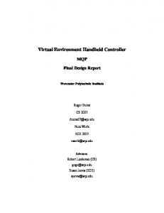
SOFTWARE ARCHITECTURE The virtual environment software was created using the Virtual Hand Toolkit™ (VHT) developed by the Immersion Corporation and the OpenGL library. The 3D models of the mechanical parts are created with Solidworks™ CAD software. These models are imported in the virtual environment by the automatic conversion of CAD files to polygonal mesh. This conversion is made by the Deep Exploration™ system. In order to organize the virtual objects information, we developed a XML modelling to describe the virtual parts and the connections which compose the parts subassemblies. The VHT system is used for collision detection, based on V-CLIP method, between virtual objects. Moreover, VHT assure the communication between the virtual scene and the interaction peripherals as the data glove, the haptic feedback system and the tracker. V-CLIP collision detection, in VHT system, is limited to convex shapes. Non-convex shapes are not considered by this collision detection system. The scene visualization is done by OpenGL graphic rendering (Figure 1).
1
Copyright © 2009 by ASME
Exporting files module Deep Exploration™
Parts design (SolidWorks)
C++
Virtual Assembly Environment (C++)
Virtual Environment Description
VHT
XML
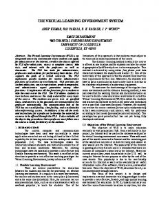
4.1 Virtual Part Design: Conversion of 3D mechanical parts to polygonal mesh generates a text file with .tri extension. This file contains the vertex and faces description of the polygonal mesh of the part (Figure 3). VHT uses this file to create a convex shape of this part. If the part shape represented by the polygonal mesh is a non-convex shape, VHT creates the equivalent convex shape. OpenGL uses the file of the polygonal mesh in order to visualize, in the virtual scene, the convex and non-convex shapes.
Collision detection (convex shapes)
Interface with user
OpenGL
Figure 1. Software architecture. 3
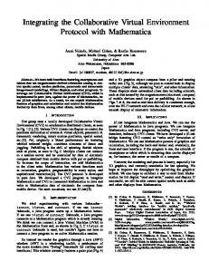
HRDWARE ARCHITECTURE The hardware architecture used to develop the virtual environment is constituted of a PC workstation with dual 2.6 GHz Xeon processors and NVIDIA QUADRO FX1000 graphics card with 128 MB of video RAM. The 3D interaction device used in this work is made of a CyberGlove™ for hand animation in the virtual scene and a CyberGrasp™ and CyberForce™ system from Immersion Corporation for the haptic rendering (Figure 2).
CyberForce CRT screen
CyberGrasp CyberGlove
PC PENTIUM IV Biprocesseur 2.6Ghz Video NVIDIA QUADRO FX1000
Force Control Unit FCU
Figure 2. Hardware architecture. 4
VIRTUAL PART MODELLING In order to represent real mechanical parts in the virtual environment, physic characteristics are applied on the geometrical models of the virtual parts. Geometrical information of position and orientation corresponding to the final assembly of each pair of parts, connected by a liaison, are determined since the product design in the CAD system.
(a) (b) Figure 3. Mechanical part model: (a) Polygonal mesh, (b) Solid model Part configuration in virtual environment is composed by its identifier, the base polygonal mesh used for its visualisation in the virtual environment, its geometrical representation in VHT system, its spatial localisation, appearance, dynamical properties and their connections with other product parts: - Identifier: name attributed for each part in order to identify it in the virtual environment, - Polygonal mesh: geometrical base data which describe the 3D part model, obtained of the conversion from 3D CAD model to polygonal representation, - VHT Object: convex geometrical model of the part created in VHT system, - Spatial localisation: position and orientation of the virtual part in the environment, - Appearance: texture and color of the virtual part, - Dynamic properties: the mass is specified in the dynamic properties of the part to be used in the force being transmitted to the user, - Connection: part connections are represented by a liaison graph created since the 3D product design. 5
ASSEMBLY MODELLING The geometrical coordinates (position and orientation) of a part with respect to other one, in the final assembly state, are determined before the assembly task execution, since the parts design in the CAD system. The virtual part manipulated by the user is called primary part. The part which will be assembled with the primary part is called receiving part. The coordinates of the final assembly
2
Copyright © 2009 by ASME
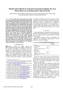
state of the primary part are expressed in the receiving part’s frame of reference. In Figure 4.a is represented a 2D graphic illustration of the final assembly state coordinates of a primary part (Part A) in the frame of reference of a receiving part (Part B). Part A assembled with Part B is represented in Figure 4.b. The frame of reference of the primary part is represented by ( x A , y A ) and the frame of reference of the receiving part is
(
)
represented by x B , y B . The coordinates of final assembly state of Part A in the receiving part, expressed in Part B frame of reference are represented by x B ( A ) , y B ( A) .
(
The origin and extremity positions of the vectors
� V2 are updated in real time with respect to the virtual world
frame of reference. In order to assemble the two parts, a geometrical transformation is applied to the primary part once the separation distance with the receiving part is equal to a value which is included in the proximity interval. Once the
�
assembly is done, both vectors ( V1 and (Figure 6).
)
Receiving part
yA yB(A)
Part A
Part A
yB
yB
yA
Part B
yB(A)
Primary part
Part B xB(A)
xB(A) xB
xB
xA
5.2 Snap Fitting Technique: Snap Fitting technique consists in the application of geometrical transformations to the primary part in order to bring it to the final assembly position and orientation with the receiving part. The Snap Fitting is activated when the distance between the primary and the receiving part is inside of a preset proximity interval. In order to realize the final phase of the assembly task, we adopted the Snap-Fitting technique proposed by Dewar et al. [1]. To improve this approach, we introduced a vector representation of the parts to assemble. A vector
� V1 = vector _ this is defined in the primary part and another ��� vector V2 = vector _ link is defined in the receiving part � (Figure 5). The direction of the vectors V1 and V2 are carried by the symmetry axis of the primary and receiving part respectively. Receiving part yB
� V2 = vector _ link
d2 zB
yA
d1
� V2 ) are overlapped
� V2 = vector _ link � V1 = vector _ this
Figure 6. Primary part and receiving part in the final assembly state la pièce primaire et la pièce réceptrice dans l’état
xA
(a) (b) Figure 4. (a) Primary and receiving part with theirs frames of reference, (b) Part A assembled with Part B.
� V1 and
5.3 Configuration of an Assembly Liaison: In our system, an assembly liaison is defined by: - the primary and the receiving part, - the primary part coordinates, in the final assembly state, expressed in the receiving part’s frame of reference, - the vectors
� � V1 and V2 defined in section 5.2.
The configuration of a liaison is constituted of: - LinkPart : the receiving part which the primary part has a connection with, - Final assembly state: position and orientation applied to the primary part in order to assemble it with the receiving part, - Status: connection state of a part : connected=1, not connected=0, - Relation vectors: the vectors 5.2.
� � V1 and V2 defined in section
6
ASSEMBLY PLANNING APPROACH Assembly planning in virtual environment presents the advantage of testing the product assemblability at the design stage. This approach allows generating the assembly plan before the physic manufacture of a product. Manual assembly may be performed once the product is fabricated or during the maintenance. Virtual assembly also allows evaluate the assembly cost or disassembly cost during the maintenance [2].
xB
xA
zA
Primary part � V1 = vector _ this
Figure 5. Representation of the vectors
� � V1 and V2
6.1 Assembly of a Mechanical System: Cylindrical parts represent between 60 and 80% of assembled automotive parts [3]. In order to generate the assembly plan in virtual environment, we have used a mechanical transmission system (Figure 7).
3
Copyright © 2009 by ASME
D
A J
B
E
C
H
L
(a) (b) Figure 7. Transmission system: a) 3D model, b) Assembly design In order to visualize the virtual assembly scene, OpenGL graphics library uses the polygonal mesh of mechanical parts. This mesh is also used by VHT system to create the convex models of virtual parts. In case of non convex shapes, VHT system generates the 3D equivalent convex model (Figure 8).
6.2.1 Parts Assembly: In order to perform the assembly operation, the user grasps the primary part, he moves it towards the receiving part, he adjust it in the assembly position and orientation and he fix it with the receiving part. During the execution of this task, the system calculates the separation distance of the grasping part with all other parts of the product to assemble. This distance is updated in real time by the V-CLIP collision detection system. In order to identify the receiving part, it is necessary to find the closest part to the grasped part. This closest part must have the possibility to be assembled with the grasped part and the assembly operation between them doesn’t must be performed before. The mating phase of assembly task is performed by the Snap-Fitting technique. The algorithm to find the receiving part is presented in Figure 9. P_TMP = null distmin = ∞ Actual_P=next part
Non convex shapes
Equivalent convex shapes
No
Possible liaison between Actual_P and grasped part No
Yes
Yes
Actual_P and grasped part are not assembled ?
Distance between Actual_P and grasped part < distmin ?
No
(a) (b) Figure 8. Convex (a) and non-convex (b) parts representation
Yes P_TMP = Actual_P distmin = Distance between Actual_P and grasped part
6.2 Snap Fitting Assembly Operation: Two parts have the possibility to be assembled if it exist a possible liaison between them. The method which we have developed in order to perform the product assembly operations is based on the verification of the connection state of each pair of parts. This state is determined by the field status in each virtual part configuration. The connection state for each part is updated in real time in order to follow the pairs of assembled parts. Virtual parts manipulation is carried out by using the next 3D interaction tools (Figure 2): - The CyberGlove™, which allows to visualize the user hand in the 3D scene, - The CyberGrasp™, to give the contact sensation between the user hand and the virtual parts, - The CyberForce™, to provide the user with weight and inertia sensation. Collision detection between virtual objects is performed by V-CLIP algorithm [4]. Parts grasping and haptic sensation are performed by some integrated algorithms in VHT system [5].
No
All parts have been verified? Yes Receiving part= P_TMP
End
Figure 9. Algorithm for determination of receiving part 6.2.2 Determination of Parts Proximity Distance: In Figure 10 are represented the distances ℓ 1 and ℓ 2 and
� V2 for an example of two cylindrical parts. � The origin (C) and extremity (D) coordinates of V1 are �
the vectors V1 and
∑ H . The origin � (E) and extremity (F) coordinates of V2 are expressed in
expressed in primary part frame of reference
receiving part frame of reference
4
∑ A.
Copyright © 2009 by ASME
� V2
W
yW
yH
E
ℓ1
xH
C
ℓ2
z H ΣA
xA
xW
zW
Figure 10. Proximity distance determination between two virtual parts � � V1 = CD , V2 = EF H
C = {i, j , k }, H D = {l , m, n}, A E = {i ' , j ' , k '} , A F = {l ' , m' , n'} The coordinates of the points
reference
∑W
W
C and H D in the frame of
are obtained by:
W C W RH = � 1 0 W RH � 0
H
W
� PH H C W D W RH • = � 1 1 1 0
W
M PFA _ H _ A is the transformation matrix of the final
assembly state coordinates of the primary part (H) expressed in the frame of reference of the receiving part (A),
yA
F D
zA
� V1
∑W
ΣH
A
M PFA _ H _ A =W M A • AM PFA _ H _ A
� PH H D • 1 1
� PH is the homogeny transformation matrix of the 1
W
M A is the transformation matrix of the receiving part’s coordinates expressed in the virtual world’s frame of reference.
6.2.3 Updating Connection Data: Once two parts are assembled, it is necessary to update the information about the connections for each part. This allows determining the connections state for each part while product is being assembled. All feasible connections are determined since the product design in the CAD system. These connections are represented in the liaison graph (Figure 11.a). When this graph is being updated in function of the realized operations, the liaisons are marked. In Figure 11.b is illustrated the liaison 4, realized between parts H and A. The status field value of the connection corresponding to Part A in the configuration of Part H is equal to 1 (status=1). And the same happens for the field corresponding to Part H in the configuration of Part A. This is in order to avoid repetitions of assembly operations when user grasps Part A.
∑W . � W RH is the rotation matrix and W PH is the position vector. In
primary part coordinates in the frame of reference
the same way, we obtain
∑W :
W E W RA = � 1 0 The distances
W
E and A F in the frame of reference
� PA A E and W F W RA • = � 1 1 1 0
W
� PA A F • 1 1
(a)
W
C E and ℓ 2 = W
(i − i' ) + ( j − j ') + (k − k ') 2
2
2
W
(b)
Figure 11. Liaison graph: (a) all possible liaisons, (b) liaison 4 is performed
ℓ 1 and ℓ 2 are obtained by: ℓ1 =
ℓ1 =
A
W
D F
, ℓ 2 = (l − l ')2 + (m − m')2 + (n − n')2
The next example presents a feasible sequence for the product assembly: S : C-B, L-J, H-A, C-A, J-H, D-C, E-B Once the sequence is finished, all the connections in the liaison graph are marked (Figure 12).
{
}
ℓ 1 and ℓ 2 are included in the predefined proximity interval ω ( ℓ 1. ≤ ω et ℓ 2. ≤ ω ), a geometrical If the distances
transformation is applied to the coordinates of the primary part in order to bring it to the position and orientation of the final assembly state with the receiving part. The geometrical coordinates of the primary part in the final assembly state are expressed in the receiving part’s frame of reference. These coordinates are obtained in the virtual world frame of reference (
W
(a) (b) Figure 12. Liaison graph evolution : (a) first operation: C-B, (b) last operation: E-B
M PFA _ H _ A ) by the next transformation:
5
Copyright © 2009 by ASME
6.3 Subassembly Manipulation: In order to assemble a product which is constituted by a lot of parts, the system must allow the subassembly manipulation. This manipulation is realized by the grasping of a part which belongs to a subassembly. This part is attached to the virtual hand. However, the whole assembly follows the movement of the grasped part. The geometrical coordinates of the subassembly parts are updated for each modification of the position and orientation of the grasped part. In order to keep the liaisons between parts of subassembly (Figure 13), an algorithm applies the geometrical transformations of final assembly state to part B to keep it fitted with part J. Then, the linked parts with part B are determined (C and E). The geometrical transformations of final assembly state of part C with part B are applied. The same happens for part E. Subassembly parts
E
8
Grasped part
C B
Figure 15: Visualization of the dynamic operation graph in the virtual scene.
J
XML MODELLING In order to allow a structured data entry to the system, we developed a XML modelling which gives capabilities to the system for being generic. With this XML modelling, any product converted to polygonal meshes can be imported in the virtual environment. The system entry consists in the creation of two XML files: the one for the parts description and the other for the connections description.
Figure 13. Subassembly manipulation 7
DYNAMIC OPERATION GRAPH GENERATION In order to provide the user with feedback information related to its actions in the virtual environment, we have included the visualization of the dynamic operation graph in the scene 3D. This graph, updated in real time, represents by icons the execution order of the connections (Figure 14). The nodes represent the product parts, the lines represent the connections and the numbers represent the execution order of each assembly operation carried out by the user. After the realization of each assembly operation, the connection between assembled parts is presented on a window in the virtual scene (Figure 15).
(a) (b) Figure 14. Assembly dynamic operation graph: (a) third operation: H-A, (b) last operation: E-B
Figure 13. Different products used in the virtual environment. 9
CONCLUSION This paper presents an approach for mechanical parts modelling in virtual assembly environment. In order to assure the assembly mating phase of virtual parts, we developed a Snap-Fitting technique based on vectors representation of the parts to assemble. The proximity computation between the primary and the receiving parts is performed by using the distance between the vectors carried by the symmetry axis of the parts to assemble. Once this distance is found in the predefined proximity interval, a geometric transformation is applied to the primary part in order to fit it into the receiving part. In this interaction mode, the behaviour of virtual parts is cinematic.
6
Copyright © 2009 by ASME
XML modelling of virtual parts allows to following the parts’ state while the product is being assembled. The actualisation of parts information will be used to edit the assembly sequence produced in the virtual environment. Moreover, XML modelling allows having a structured data entry for the connections of each part. In order to keep the connection stability, when subassemblies are manipulated, the positions and orientations of the connected parts are actualised by applying geometrical transformations corresponding to the coordinates of each pair of parts in their final assembly state. In order to represent the user operations, we have included the visualisation, in real time, of the liaison graph and the dynamic assembly operation graph. The preliminary study of system performance shows that the graphs visualisation allows to the user an information feedback which is useful for the optimisation of assembly planning strategy. According to the realised assembly trials, we have ascertained the interpenetration of geometrical models of the parts during the mating phase. This interpenetration may carry out to the generation of unfeasible assembly plans in real world. In order to include the geometrical reasoning and precedence relationship between parts, a technique of virtual parts modelling based on the spring-damper model has been developed[6]. This technique allows having a virtual part’s realistic physical behaviour without interpenetration of 3D geometrical models.
REFERENCES [1] R. G. Dewar, I. D. Carpenter, J. M. Ritchie, and J. E. L. Simmons, "Assembly planning in a virtual environment," presented at Portland International Conference on Management and Technology (PICMET ’97), Portland, 1997. [2] P. Coiffet and S. Garbaya, "Using VR techniques for product life-cycle evaluation in the design stage," presented at International IFIP Conference on Feature Modelling and Advanced Design for the life cycle systems, Valenciennes, France, 2001 [3] A. Delchambre, "A pragmatic approach to computeraided assembly planning," presented at IEEE International Conference on Robotics and Automation, 1990. [4] B. Mirtich, "V-Clip: Fast and Robust Polyhedral Collision Detection," MITSUBISHI ELECTRIC RESEARCH LABORATORIES, Technical Report: TR97-05 1997. [5] R. Carmel, C. Ullrich, and J. Silver, "VirtualHand v2.5 Programmer’s Guide," Virtual Technologies, Inc., Technical Report 2001 [6] S. Garbaya and U. Zaldivar-Colado, "The affect of contact force sensations on user performance in virtual assembly tasks," Virtual Reality, vol. 11, pp. 287-299, 2007.
7
Copyright © 2009 by ASME