Realizing Live Sequence Charts in SystemVerilog Hai H. Wang School of Electronics and Computer Science University of Southampton
[email protected] Jun Sun School of Computing National University of Singapore
[email protected]
Abstract The design of an embedded control system starts with an investigation of properties and behaviors of the process evolving within its environment, and an analysis of the requirement for its safety performance. In early stages, system requirements are often specified as scenarios of behavior using sequence charts for different use cases. This specification must be precise, intuitive and expressive enough to capture different aspects of embedded control systems. As a rather rich and useful extension to the classical message sequence charts, Live Sequence Charts (LSC), which provide a rich collection of constructs for specifying both possible and mandatory behaviors, are very suitable for designing an embedded control system. However, it is not a trivial task to realize a high-level design model in executable program codes effectively and correctly. This paper tackles the challenging task by providing a mapping algorithm to automatically synthesize SystemVerilog programs from given LSC specifications.
1 Introduction The design of an embedded control system is ideally decomposed into a progression of related phases. It starts with an investigation of properties and behaviors of the process evolving within its environment, and an analysis of the requirement for its safety performance. From these is derived a specification of program-centered components of the system. The process then may go through a series of design phases, ending in a program expressed in a high level language. After translation into a machine code of a chosen computer, it can be executed at a high speed by electronic circuits. In order to achieve time performance required by
Shengchao Qin Department of Computer Science, Durham University.
[email protected] Jin Song Dong School of Computing National University of Singapore
[email protected]
customers, additional application-specific hardware devices (e.g., ASICs or FPGAs) may be added to embed the computer into the system which it controls. The derivation of low-level implementation from high-level, referred as synthesis, is a complicated process which requires tool assistance. In early stages of system engineering, system requirements are often specified as scenarios of behavior using use cases or sequence charts. A use case is an informal description of a collection of possible scenarios involving the system’s components and its environment, while sequence charts provide a formal means for specifying the scenarios that instantiate the use cases. As a popular requirements language, sequence charts like UML Sequence Diagrams [25] and ITU standard Message Sequence Charts (MSCs) [15] have been used to capture the desired interrelationships between system components and between them and the environment. These sequence charts often state what might possibly occur, not what must occur, which means that they are not enough if we want to specify the actual behavior of a reactive system in a scenario-based fashion. To overcome this potential limitation in expressive power, Damm and Harel [8] extended MSCs to incorporate liveness properties, yielding a new sequence-based language called Live Sequence Charts (LSCs). LSCs may state scenarios that must occur. For instance, a universal chart, possibly preceded with a pre-chart, specifies mandatory behaviors globally, i.e., once the system behavior matches its pre-chart, the subsequent behavior must follow the main chart. On the level of a chart, events and conditions and locations are also labelled with modalities. LSCs also provide structuring constructs, like sub-charts, branching and iterations, to build scenarios hierarchically. As a rather rich and useful extension to MSCs, LSCs provide a rich collection of constructs for specifying both
chart. Whenever a communication sequence matches the pre-chart, the system must proceed as specified by the main chart. A system run may activate a universal chart more than once and some of the activations might overlap [18].
possible and mandatory behaviors. The play engine for LSCs [12] provides an intuitive and easy way for system designers to play in expected scenarios of behavior and play out LSC specifications for verification and validation purposes. For these reasons, we have decided to take LSCs as the behavioral specificationlanguage in our framework for embedded system design. In [23], a method of generating Verilog programs from Statechart [9] has been proposed. Compared to Statechart, LSC serves a natural notation for stating scenario-based system requirements, which is involved in even earlier stage of system development. After an LSC specification has been played-in and verified/tested using the play-out engine, an immediate question is, how can we generate executable program code in order to proceed to the next development stage? This paper is to tackle this challenging problem by providing a mapping algorithm to automatically synthesize SystemVerilog programs from given LSC specifications. We choose SystemVerilog as a target language for our synthesis process partly because our overall aim is to develop hardware/software mixed embedded systems, whereas SystemVerilog is a language suitable for both behavioral and structural specifications of such systems. Moreover, SystemVerilog supports assertions which can potentially be used to specify certain requirement constraints carried over from LSC specifications including liveness properties and non-functional constraints. The tool supports available for SystemVerilog also allows u to verify/simulate the system design before the hardware/software partitioning process. Most importantly, SystemVerilog is popular in industry, e.g., it has been standardized by IEEE. This remainder of the paper is organized as follows. Section 2.1 briefly introduces the notion of LSC. Section 2.2 review the relevant features of SystemVerilog. Section 3 is devoted to a mapping from LSC specifications to SystemVerilog programs and a brief discussion of its correctness. Section 4 concludes the paper and discusses possible future works.
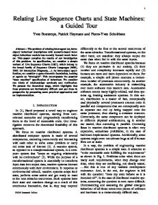
Universal chart Figure 1 shows a universal chart as part of the mobile phone specification. This scenario OpenCover illustrates the interaction between the objects when the user opens the cover. Once the cover is opened by the user, the main chart is activated. The chip is notified that the cover is opened. If the phone is not playing music, the chip requests the display to display the main menu. Otherwise, the music menu shall be displayed. The dot-lined diamond shape denotes a cold condition. We remark that all vertical lines are dotted in this chart and, therefore, all locations are cold. Lastly, the display carries out a respective local action, setMainMenu or setMP3Menu, to initialize the phone screen. 2 In this work, we focus on universal charts. Existential charts are used for generating test benches in later stages. Each chart is associated with a set of visible events. Only events visible to a chart are constrained by the chart. A chart typically consists of multiple instances (for instance, User, Cover, Chip and Display), which are represented as vertical lines graphically. Along with each line, there is a finite number of locations. A location carries the temperature annotation for progress within an instance. Intuitively, locations can be thought as the joint points of instance lines and message lines. A location may be labelled as either cold or hot. A hot location means that a system run reaching this location has to move beyond. A system run may stay put at a cold location forever. Similarly, messages and conditions are also labelled. A hot message must be received, whereas a cold one may get lost. A hot condition must be met, whereas violation of a cold condition terminates the chart. A location is labelled with a finite number of events (more than one if it is a co-region) and at most one condition.
2 Background 2.1
Mobile phone specification The universal charts in Figure 2 and the one in Figure 1 constitute a self-containing set of scenarios, which specify a mobile phone specification. This example is partially inspired by the phone system specification presented in [13]. The system consists of six participating objects, a user, the cover, the display, the speaker, the chip and the environment where the incoming calls are from. Figure 2 illustrates scenarios of the system besides OpenCover, i.e., the user closes the cover, an incoming call arrives and the user picks up the phone and talks. All vertical lines in the charts are dotted, which means that all locations along the lines are cold and, therefore, the system may pause at any point of execution forever. This is possible because unexpected events like the battery runs out
Live Sequence Charts
There are two kinds of charts in LSC. Existential charts are mainly used to describe possible scenarios of a system in the early stage of system development, i.e., the same role played by MSC except that existential charts are scoped. In later stages, knowledge becomes available about when a system run has progressed far enough for a specific usage of the system to become relevant. Universal charts are then used to specify behaviors that should always be exhibited. A universal chart is typically preceded with a prechart, which serves as the activation condition of the main 2
OpenCover User
Cover
Chip
Display
open
coverOpened status!=mp3 displayMainMenu setMainMenu displayMP3Menu setMP3Menu
Figure 1. Phone System Scenario: OpenCover or the system breaks down may occur at any time. The set of visible events for each chart are exactly those appeared in the diagram except the scenario Talk. The message close from the user to the cover is forbidden in the scenario Talk, i.e., in order to carry out the scenario successfully, the user should not close the cover before the scenario completes. 2
Verification Language) with ease of Verilog to provide a single platform for both design and verification. A SystemVerilog model is composed of modules, which define nets connected by wires. Nets are composed of processes (threads of executions), which execute statements. The statements in SystemVerilog can be divided into two groups – blocking statements and non-blocking statements. Each individual statement can be labelled.
LSC also supports advanced MSC features like coregion, hierarchy, etc. Moreover, symbolic instances and messages are used to group scenarios effectively. For a detailed introduction on a complete list of features of LSC, refer to [12]. LSC is far more expressive than MSC, which makes it capable of expressing complicated scenario-based requirements. However, we remark that the ability to specify hot and cold messages, i.e., whether a message is required to be received or may get lost, is redundant because of the facility for describing hot and cold locations. Essentially, the temperature of the locations takes precedence over the temperature of messages, so whether or not the message is received is determined entirely by the temperature of the message input. This questionable feature of LSC is recognized by Harel and Marelly who list the possible cases and conclude that the temperature of messages has no semantic meaning [12]. Thus, in the following discussion, the temperature of messages is discarded.
2.2
Blocking assignments, which may or may not being attached with a time specification, block the execution of a process until their completion. When a blocking assignment is executed, an event e is generated and added to the global event queue EventQ. Blocking assignment statements are sequential statements. Non-blocking assignment statements, like always, fork...join, and implicit wire assignment statements, generate non-blocking region update events. Non-blocking assignment statements are concurrent assignments. The statements can be grouped into a single begin − end or fork − join block. The modules in SystemVerilog are often connected using interfaces, which provides a high level of abstraction of connections. An interface is defined independent from modules. SystemVerilog has a set of build-in datatypes and users can also define their own complex data structures. SystemVerilog also provides several powerful ways for synchronizing parallel activities within a design or a test bench.
SystemVerilog
SystemVerilog, as one of the latest releases from IEEE for the hardware design languages, extended Verilog by combining the Verification capabilities of HVL (Hardware
For more information about SystemVerilog, please refer to [1]. 3
CloseCover User
Cover
Chip
Display
close
coverClosed displayTime setDisplayTime
Receive Env
Chip
Speaker
Display
incomingCall
startRing displayCallerID setDisplayCaller Talk Env
User
Cover
Chip
open
Speaker
Display
startRing coverOpened
speakerOff displayTimer
talk
setDisplayTimer
Forbidden Elements LSC
close
Figure 2. Mobile phone system scenarios
4
3 From LSCs to SystemVerilog
1. module Phone (...ports...); 2. //ports 3. //variables 4. //tasks and functions 5. //control processes 6. User user(...ports...); 7. Env env(...ports...); 8. Cover cover(...ports...); 9. Chip chip(...ports...); 10. Display display(...ports...); 11. Speaker speaker(...ports...); 12. endmodule
In this section, we build a link between LSC specifications and SystemVerilog programs, i.e., an LSC specification is mapped into a corresponding SystemVerilog program. We show that such a mapping can be conducted in a compositional manner. Moreover, the SystemVerilog program is modular and, therefore, allows possible later software/hareware partitioning.
3.1
The Synthesis Problem
In an LSC specification, an object may participate in multiple universal charts playing different roles, e.g., the object Chip in the universal charts. A good practice of implementing the system, however, is that the behaviors of each object should be encapsulated in one package (a class or module) for easy maintenance as well as code reusing. In this work, we not only want to systematically construct a SystemVerilog program which is equivalent to the LSC model, but also to do it in such a way that each object in the LSC specification is mapped to a module in the SystemVerilog program. Thus, the module groups all roles that the object plays in the universal charts. The system then consists of instances of all object modules running in parallel. In another words, we are tackling an instance of the distributed synthesis problem. Distributed synthesis is computationally expensive in general [19] and in the case of LSC [6]. The approach we use follows the practical solution offered in [20] and later in [21], which sacrifices completeness in exchange of an efficient and sound way of synthesizing a distributed system. The key idea is of using a fixed implementation template to avoid undecidability, i.e., using a bounded set of synchronization events to monitor global completion of universal charts locally so that the global state machine is never constructed. However, the works in [20, 21] never yield any executable program like SystemVerilog. By using unique constructors like always offered in SystemVerilog, we show that we are able to not only realize their solution but also make the solution even simpler.
3.2
Figure 3. Top-level module example
tem can be connected to its environment. For instance, the ports will be connected to a test bench during system simulation. After the input/outputs definitions, all global variables (including variables dedicated to a universal chart) are declared, which will be wired to the relevant object (as we shall see later). This top level module also contains a set of tasks and function definitions, which correspond to the external functions and conditions in the universal charts. In addition, there is a set of controlling processes to ensure the correct order of execution. For the moment, we omit the details. The key point here is that there should be one module defined for each object type in the system and an object is defined as an instance of the module (which is defined in the top-level module). For instance, we have a module named Cover corresponding to the object Cover in the specification. The object cover is defined as an instance of the module Cover. The module defining the object type shall group all its roles in different universal charts, e.g., instance cover shall be able to participate in all three charts shown in Figure 2. Moreover, we shall be able to identify which role to act dynamically during system runs. The details of the module Cover will be shown later. All the objects are running concurrently. We do have modules defined the two environmental objects User and Env. This may suggest that we only deal with closed systems, i.e., environmental objects are manipulated as if they are parts of the system. We remark that we do handle open systems. The users (or system specifiers) are asked to distinguish the environmental objects from system objects. The modules synthesized for the environmental objects are indeed processes which monitor the interaction between the system and its environment so as to trigger the controlling events at the right execution point. This is a practical approach to avoid the undecidability of the distributed synthesis problem for open systems. In
SystemVerilog Realization
In the following, we will walk through the mappings informally using the cell phone examples. A set of mapping rules will be presented later in this section. Figure 3 shows the top-level module of the SystemVerilog program synthesized from the phone system specification. It encapsulates everything about the phone specification. The parameters specify the communication interface. This is necessary because reactive systems constantly interact with their environments. Through the ports, this sys5
event open is monitored, the process signals the controlling process in the module Phone (the third line above). It says that the object Cover is now ready to proceed to the main chart of the chart OpenCover (by negating the value of cover open cover main). The fourth line sets a flag to indicate that the chart OpenCover has been activated.
1. module Cover (· · · ports · · ·); 2. //ports 3. //variables 4. //controlling process 5. //for the role in chart OpenCover 6. always@(open) begin · · · end 7. //for the role in chart CloseCover 8. always@(close) begin · · · end 9. //for the role in chart Talk 10. always@(open) begin · · · end 11. endmodule
1. always@(cover open cover main) 2. begin 3. @user open cover main; 4. open cover main =!open cover main; 5. end The above is a controlling process in the top-level module. There is such a process for each and every universal chart. Once the object cover declares that it is ready to enter the main chart (by event @cover open cover main), the process waits for other participating objects to declare the same. Once all objects are ready, it triggers the event @open cover main so that all object enters the main simultaneously.
Figure 4. Object type module example other words, we achieve a correct-by-construction method by paying a reasonable price. A related work on adding liveness assumption on the environment to ease the distributed synthesis problem was discussed in [6]. The work in [21] discussed a similar approach using a partial modelling of the environment. Grouping different roles of an object in one module requires identifying which role an object is to play dynamically. According to LSC semantics, all visible events of a chart shall be monitored constantly. Whenever the pre-chart of a universal chart is matched, the participating objects shall cooperate to proceed as specified by the main chart, i.e., the objects shall play their roles corporately. Thus, we need controlling processes which dynamically decide whether a pre-chart has been matched and if all participating objects in the universal chart are ready to proceed to the main chart. Inside the module for an instance, there are ports definitions, variable definitions as well as controlling processes. Besides, there is one always block for each role which the object could play in the universal charts. For instance, in the module presented in Figure 4, there is one always block for each role which the Cover plays in the charts. The role is activated only if the sequence of events on the instance in the pre-chart of the universal chart is matched. For instance, the always block for the role in OpenCover is activated only if the event open is engaged. Once activated, the object must play its role in the main chart.
1. always @((open cover main or cancel open cover) 2. iff open cover activated == 1) 3. if (open cover main) begin 4. coverOpened = !coverOpened; 5. end else begin 6. if (cancel open cover) begin 7. $display(′′ Chart canceled.”); 8. end 9. end Once all the instances are ready to participate in the scenario, the controlling process synchronizes the entering of the main chart among all participating instances. In the modules for each participating objects, there is an always block like the above which responds to either open cover main (meaning the object shall proceed to the main chart of OpenCover) or cancel open cover (meaning the activation has been terminated). The activation of the chart may be terminated if an unexpected event (associated with this object or other objects) is engaged. For instance, the trace hopen, speakerOff i shall trigger and then terminate the chart Talk. In that case, the event cancel open cover is synchronized among the activated instances so that the corresponding processes will be terminated. If the event open cover main is engaged (the third line), the events in the main chart occur in the time step (the fourth line). The duration of a time step can be set as a user option. In one time step, a super step of the LSC specification [12] is carried out unless there is explicit delay (specified using timeout construct in LSC) in the chart. We do require that the internal computation and communication shall be faster than the arrival of external stimuli.
1. always @(open) 2. begin 3. cover open cover main = !cover open cover main; 4. open cover activated = 1; 5. end The above is the process capturing the role of the object Cover in the pre-chart of chart OpenCover. Whenever the 6
i1
i1
i2
i2
e1
e2
e2
e3
e
e
Figure 5. Example charts: synchronization As you have seen, events in LSC are mapped to primitive SystemVerilog commands. For instance, message sending is mapped to event output and message receiving is mapped to event input. So are those compositional constructs like sub-chart, iteration and conditional branch, which have their exact images in the SystemVerilog language. One problem we face when we do the mapping is that SystemVerilog lacks the support for barrier synchronization among multiple processes. Yet, it is unavoidable in LSC models and necessary for synthesizing SystemVerilog programs. For instance, each and every horizontal line in the specification represents a barrier synchronization, e.g., the horizontal line right after the pre-chart synchronizes the entering of the main chart among all participating instances. A shared condition, e.g., the cold condition in the chart OpenCover, synchronizes multiple instances as well, e.g., Chip and Display. We have already discussed how to synchronize the entering of a main chart. The same strategy is applied for other barrier synchronization. That is, before entering a sub-chart, all participating objects shall signal a controlling process in the Phone module, and later enter the sub-chart at once. Furthermore, barrier synchronization is needed for events visible to multiple universal charts. An event visible to multiple universal charts are allowed to engage if and only if all activations of the universal charts are ready to engage in the event.
synchronization in SystemVerilog to simulate the effect of barrier synchronization. Each event (as well as local actions) is associated with an event handler. Only the handler is capable of engaging the event. Whenever an activated role of an instance enters the main chart of the respective universal chart, it will register the set of visible events of the chart that are associated with the instance. It is done by synchronizing a set of special events with the event handlers associated with the events. Whenever a role of the instance is ready to engage in a common event, it synchronizes with the event handler. The event handler checks whether all registered roles are ready to engage in the event. If they do, the controlling process will engage in the event and so all the instances proceed. Otherwise, the event handler simply waits. For instance, if both e1 and e2 have engaged, because e has been registered by different roles, it can be engaged only after e3. Example For simplicity, we use the example in Figure 6 to illustrate our solution to the barrier synchronization. It is a simple program generated from the charts in Figure 5.2 Once event e1 is engaged, counter e is incremented. counter e is incremented again after event e2 is engaged. Then object i1 declares that it is ready to engage e by engaging in event ready e. Since counter e is greater than 1, it will be decremented by 1. Later, the object i2 declares it is ready to engage e. Because now counter e is of value 1, the event fire e is engaged, which gives the permission for the objects to engage in event e. 2
Example In Figure 5, after the occurrence of event e1 and e2 , the event e can only be engaged after event e3 because e is synchronized by the two charts. The problem is further complicated as the event could be visible to multiple universal charts and each chart may be activated many times.
All variables in the LSC specification are mapped to variables in the top level module of the SystemVerilog program. They are wired to the relevant instance module if necessary. Local actions and conditions in the LSC specification are mapped to tasks and functions in the top-level module. We remark that making the variable globally accessible is unavoidable if we are to support shared conditions in LSC. For instance, the following is a task and function definition appeared in the chart OpenCover:
2
In general, there could be infinite overlapping activations of the same chart. The good news is that there is always a symmetry reduction which reduces the infinite overlapping activations to finite many1 . We make use of the simple event 1 In [6], Bontemps and Schobbens have shown that every LSC has an equivalent deterministic B¨uchi automaton that contains at most exponentially more states than there are locations in the LSC.
2 To save space, we have removed synchronization on entering the main chart, the module structure, etc.
7
mapped to a module in the SystemVerilog program.
1. bit e1, e2, e3, e, fire e, ready e; 2. byte unsigned counter e; 3. always@(ready e iff counter e == 1) 4. begin 5. fire e = !fire e; 6. counter e = 0; 7. end 8. always@(ready e iff counter e > 1) 9. counter e = counter e − 1; 10. always@(e1) 11. begin 12. counter e = counter e + 1; 13. e2 =!e2; 14. ready e = !ready e; 15. @fire e e =!e; 16. end 17. always@(e2) 18. begin 19. counter e = counter e + 1; 20. e3 =!e3; 21. @fire e e =!e; 22. end
– For each role which the object could play in the universal charts, there is one always block. – Events, variables, functions visible to the object are wired from the top-level module to the object type module. • Rule 3: Existential charts – Existential charts are mapped to test benches.
3.3
Discussion
In this section, we briefly discuss the soundness of the transformation. We adapted the LSC semantics presented in [8] and extended in [22]. In a nutshell, the semantics of a basic chart, i.e., Basic-MSC [15], is defined to consist of all runs compatible with the partial ordering induced by the chart and its annotations. The semantics of existential charts is different from that of basic charts because existential charts, as universal charts, are scoped. Events invisible to the chart may occur freely between any two successive events in an execution of the chart. In this work, existential charts are used to illustrate test cases only. Lastly, a trace violates a universal chart if and only if it completes the prechart but fails to conform to the main chart. In [20], Sun and Dong have proved that distributed processes can be synthesized by using a bounded set of systemization events. Their idea is to monitor possible completion of the pre-charts and trigger synchronization events at the proper execution time. A similar idea has been adapted in this work. Furthermore, using SystemVerilog allows us to simplify the task of monitoring possible matching of a prechart because of the distinguishable always construct. That is, an always-block is activated if a given event sequence occurs, which closely corresponds to the semantics of prechart. Therefore, the soundness of our approach is a consequence of the result proved in [20] and the semantics of the always construct.
Figure 6. Barrier synchronization example 1. function bit Con1(); 2. if (state! = mp3) begin 3. return 1; 4. end else 5. begin 6. return 0; 7. end 8. endfunction 9. tasksetMainMenu(); 10. //procedural codes 11. endtask We summarize our transformation rules as follows:
4 Conclusion
• Rule 1: Top-level module – An LSC specification is mapped to a top-level SystemVerilog module.
In this work, we have developed a strategy for systematically generating a SystemVerilog program from LSC specifications. In our system development process, system engineers shall specify the system requirements using the notion of LSC. After an LSC specification has been played-in and verified/tested using the play-out engine, a prototype SystemVerilog program is generated for the next stage of system development. System engineers are encouraged to use assertion offered by SystemVerilog tools to simulate, verify and refine the generated prototype if necessary. Once the
– An object is mapped to an instance of the object type module in the top-level module. – Variables and functions are mapped to variables and tasks in the top-level module. • Rule 2: Object type module – Each object type in the LSC specification is 8
system design is fully verified, SystemVerilog tools can be used for software/hardware partition process. As for future works, we plan to develop a reliable tool support for our approach. Furthermore, the natural problem we want to tackle is to find a systematic and efficient partition strategy. As mentioned earlier, we made the assumption that all message passing are all synchronized for simplicity. Asynchronous message passing can be supported by explicitly modelling the behaviors of the communication buffer. Using advanced features like interfaces in SystemVerilog, we believe it should be reasonably straightforward. Our mapping does omit some features of LSC, for instance, the modality of locations and existential charts. The modality of locations, i.e., whether the system shall move beyond the location, is indeed liveness constraints. We believe it is not something to be taken care of during the synthesis process. Rather, it shall be tested or asserted using assertions after the SystemVerilog program is synthesized. Our generation is based on universal charts. Existential charts are used to generate test benches. For instance, Figure 7 shows an existential chart illustrating the most common scenario of the phone system. The difference between classic MSCs and existential charts is that existential charts are more abstract, i.e., only visible events are required to occur in the specified sequence. We make use of the SystemVerilog language construct $monitor to monitor the visible events only and test whether the events happen in the given order. As for related works, the synthesis problem of MSC has been studied extensively [3, 2, 17, 24, 16, 17, 14]. The synthesis problem of LSC is initially discussed by Harel and Kugler in [10], in which they tackled the problem by defining the notion of consistency of LSC models. Their approach starts with constructing a global system automaton and decomposes it by different means (refer to [10] for details). Their approach suffers from the state explosion problem due to the construction of the global system automaton, which is often of huge size because of the distributed nature of LSC and the underlying weak partial order semantics. The characteristic of our work is that we synthesize a modular SystemVerilog program which allows a reasonably large set of behaviors permitted by the LSC specification. In [7], Bontemps, Schobbens and L¨oding discussed the synthesis problem for a small subset of LSC (LSC without conditions, structuring constructs, modalities on locations and messages). They proposed a game-based semantics for LSC, which leads to the notion of consistency of their LSC. Their work is later extended to handle all LSC constructs but unbounded loop in [4]. In our approach, almost all LSC constructs are supported except complex time-related ones. In [6], Bontemps and Schobbens investigated the complexity of various problems associated with LSC. The results are pretty negative, i.e., they showed that centralized model-
checking of LSC is Co-NP-complete, the distributed modelchecking is PSPACE complete and the distributed realization problem is undecidable. In our work, we use a set of special events (bounded by the maximum number of overlapping activation of the universal charts and the number of the universal charts) to avoid undecidability. Thus, our work can be viewed as a lightweight approach. In [11], Harel, Kugler and Pnueli re-investigated the synthesis problem of LSC by adopting a lightweight approach as well, i.e., they generate Statecharts from LSC and then verify them for correctness, and thus avoid undecidability. A similar approach is evidenced in [5], where Bontemps and Egyed proposed a technique coupling translation and verification to cope with undecidability. We remark that such an approach certainly works for our approach as well except that we must deal the complexity of model-checking of complicated distributed systems. In our approach, there is a cheaper way to make sure that our synthesized program does satisfy all the universal charts. That is, we generate SystemVerilog monitoring processes (one for each universal chart) from the same LSC specification and simulate the program alongside the monitoring processes. In [20], Dong and Sun tackled the synthesis problem of LSC using the notion of CSP and its algebraic laws. The difference between their work and ours is that we target at concrete implementation which favors later development.
Acknowledgment Hai H. Wang is supported in part by the EU-funded TAO project (IST-2004-026460). Shengchao Qin is supported in part by the EPSRC funded project EP/E021948/1.
References [1] Accellora Org. SystemVerilog 3.1a Language Reference Manual . http://www.eda.org/sv/ SystemVerilog$\_$3.1a.pdf, 2001. [2] R. Alur, K. Etessami, and M. Yannakakis. Inference of Message Sequence Charts. In Proceedings of the 22nd International Conference on Software Engineering, pages 304–313. ACM Press, 2000. [3] R. Alur and M. Yannakakis. Model Checking of Message Sequence Charts. In Proceedings of the 10th International Conference on Concurrency Theory, pages 114–129. Springer, 1999. [4] Y. Bontemps. Relating Inter-Agent and Intra-Agent Specifications (The Case of Live Sequence Charts). PhD thesis, Facult´es Universitaires Notre-Dame de la Paix, Institut d’Informatique (University of Namur, Computer Science Dept), April 2005. [5] Y. Bontemps, P. Heymans, and P. Schobbens. Lightweight Formal Methods for Scenario-Based Software Engineering.
9
Receive&Talk Env
User
Chip
Speaker
Cover
incomingCall startRing open speakerOff talk
Figure 7. Existential chart [17] K. Koskimies and E. M¨akinen. Automatic Synthesis of State Machines from Trace Diagrams. Softw. Pract. Exper., 24(7):643–658, 1994.
In S. Leue and T. Systa, editors, Scenarios, volume 3466 of Lecture Notes in Computer Science, pages 174–192, 2005. [6] Y. Bontemps and P. Schobbens. The Complexity of Live Sequence Charts. In Foundations of Software Science and Computational Structures, 8th International Conference, FOSSACS 2005, pages 364–378, 2005.
[18] R. Marelly, D. Harel, and H. Kugler. Multiple Instances and Symbolic Variables in Executable Sequence Charts. In Proceedings of OOPSLA’02, pages 83–100, 2002.
[7] Y. Bontemps, P. Schobbens, and C. L¨oding. Synthesis of Open Reactive Systems from Scenario-Based Specifications. Fundamenta Informaticae, 62(2):139–169, July 2004.
[19] A. Pnueli and R. Rosner. Distributed Reactive Systems are Hard to Synthesize. In Proceedings 31st IEEE Symposium on Foundation of Computer Science, 1990.
[8] W. Damm and D. Harel. LSCs: Breathing Life into Message Sequence Charts. Formal Methods in System Design, 19(1):45–80, 2001.
[20] J. Sun and J. S. Dong. Synthesis of Distributed Processes from Scenario-Based Specifications. In J. Fitzgerald, I. J. Hayes, and A. Tarlecki, editors, Formal Methods 2005, volume 3582 of Lecture Notes in Computer Science, pages 415– 431. Springer, 2005.
[9] D. Harel. Statecharts: A Visual Formulation for Complex Systems. Science of Computer Programming, 8(3):231–274, 1987.
[21] J. Sun and J. S. Dong. Design Synthesis from Interaction and State-Based Specifications. IEEE Trans. Software Eng., 32(6):349–364, 2006.
[10] D. Harel and H. Kugler. Synthesizing State-Based Object Systems from LSC Specifications. International Journal on Foundations of Computer Science, 13(1):5–51, 2002.
[22] J. Sun and J. S. Dong. From Live Sequence Charts to Implementation. Technical Report TRA1/07, National University of Singapore, January 2007. http://www.comp.nus.edu.sg/˜sunj/Reports/proof.ps.
[11] D. Harel, H. Kugler, and A. Pnueli. Synthesis Revisited: Generating Statechart Models from Scenario-Based Requirements. In Formal Methods in Software and Systems Modeling, pages 309–324, 2005.
[23] Viet-Anh Vu Tran, Shengchao Qin, and Wei-Ngan Chin. An Automatic Mapping from Statecharts to Verilog. In Zhiming Liu and Keijiro Araki, editors, First International Colloquium on Theoretical Aspects of Computing (ICTAC 2004), volume 3407 of Lecture Notes in Computer Science, pages 187–203. Springer, 2004.
[12] D. Harel and R. Marelly. Come, Let’s Play - Scenario-Based Programming Using LSCs and Play-Engine. Springer, 2003. [13] D. Harel and R. Marelly. Play-Engine User’s Guide, 2003. [14] O. Haugen and K. Stølen. STAIRS - Steps to Analyze Interactions with Refinement Semantics. In Perdita Stevens, Jon Whittle, and Grady Booch, editors, UML 2003, volume 2863 of Lecture Notes in Computer Science, pages 388–402. Springer, 2003.
[24] S. Uchitel and J. Kramer. A Workbench for Synthesising Behaviour Models from Scenarios. In ICSE 2001, pages 188– 197. IEEE Computer Society, 2001. [25] UML Group. OMG UML Version 1.5. http://www.uml.org/, June 2002.
[15] ITU. Message Sequence Chart(MSC), Nov 1999. Series Z: Languages and general software aspects for telecommunication systems. [16] P. Kosiuczenko and M. Wirsing. Formalizing and Executing Message Sequence Charts via Timed Rewriting. Electrical Notes on Theoretical Computer Science, 25:1–25, 1999.
10