input from an internally calibrated monocular video camera of a static scene to ... straints on matches) in the initial structure and motion esti- mation, and robust ...
Realtime visualization of monocular data for 3D reconstruction Adam Rachmielowski, Martin J¨agersand, Dana Cobzas¸ CS, University of Alberta, Canada
Abstract Methods for reconstructing photorealistic 3D graphics models from images or video are appealing applications of computer vision. Such methods rely on good input image data, but the lack of user feedback during image acquisition often leads to incomplete or poorly sampled reconstruction results. We describe a video-based system that constructs and visualizes a coarse graphics model in real-time and automatically saves a set of images appropriate for later offline dense reconstruction. Visualization of the model during image acquisition allows the operator to interactively verify that an adequate set of input images has been collected for the modeling task, while automatic image selection keeps storage requirements to a minimum. Our implementation uses real-time monocular SLAM to compute and continuously keep extending a 3D model, augments this with keyframe selection for storage, surface modelling, and on-line rendering of the current structure textured from a selection of key-frames. This rendering gives an immediate and intuitive view of both the geometry and if suitable viewpoints of texture images have already been captured.
1. Introduction Image-based modelling and rendering techniques aim to create more photorealistic graphics models with less user labour and hardware requirements compared to alternative methods such as manual 3D modelling (in a CAD or modelling software) or laser-scanning. There exist many imagebased techniques such as those that are suitable only for objects (e.g. shape-from-silhouettes), those that require calibrated or structured light, techniques that are purely imagebased and encode no surface geometry, or those that require multiple calibrated cameras for stereo measurements. However, in this paper we are concerned with methods that take input from an internally calibrated monocular video camera of a static scene to automatically reconstruct surface geometry and appearance. While turntable-based systems for automatically creating graphics models of objects have already moved from
research to the commercial domain [1, 3, 2], scene modelling systems are slower to make this transition. One problem with such systems is the input data: the images/video for the reconstruction must adequately sample the plenoptic function of the scene. Systems such as KU-Leuven’s ARC 3D [20], which allows users to upload a set of images and produce a scene reconstruction, wisely guide users to avoid taking images with only panning motion, motion only in the direction of the scene, or images of mostly planar or homogeneous objects. Experts in this field know that such degenerate image sets lead to failed reconstructions because of poorly conditioned SFM estimation or poor feature correspondences. Nevertheless, even experts are faced with inadequate reconstructions when relying on the current paradigm: go to the site, collect the data (images), then return to the lab to perform the reconstruction. Reconstructions may be inadequate because important surfaces were sampled poorly or not at all, requiring a return to the site to collect more data. Also, lack of connecting keyframes may lead to multiple reconstructed pieces that must later be hand registered. We believe providing user feedback during capture and automatically storing useful images is an effective way to solve these problems. The system described herein maintains a real-time estimate of the camera position as the user moves around the scene. To minimize data storage requirements a subset of the images from the video are saved to disk. A coarse surface model is estimated and textured with the saved images to give the user immediate feedback on their progress. In the remainder of this paper, we first review monocular scene modeling and probabilistic camera tracking and structure estimation (section 2). Next, the two main system components (tracking and visualization) are described (section 3). Finally, experimental results from an indoor scene capture are provided (section 4).
2 Related Work 2.1
Monocular Scene Modelling
A typical automatic monocular scene modelling system works as follows. First, in a 2D image processing stage fea-
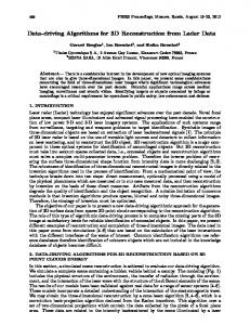
The early work of Beardsley et al. [4] uses Harris corners as well as lines for features, image triples (for strong constraints on matches) in the initial structure and motion estimation, and robust RANSAC computations for all estimation (fundamental matrix, trifocal tensor, resection, triangulation). The system of Pollefeys [13] is designed specifically for video, uses image pairs (for longer feature tracks), incorporates a simple measure of inter-frame distance (by model selection), and adds the step of dense surface modelling to the process. More recent systems build on this same approach while for example: handling larger input sets [17], automatically fitting scene planes and polygonal primitives [21], or incorporating different surface appearance models [12]. This work aims to be a useful addition to any of the above systems, as well as existing sequential/incremental structure and motion estimation methods [6, 5, 7, 15], which provide visualization of the reconstructed scene model only in the form of point clouds. Our approach is similar in spirit to the system of Rusinkiewicz et al. [18], which acquires dense 3D geometry-only surface models in real-time with feedback. However, their system requires structured light from a projector and works only for diffuse objects. Another system by Fudono et al. [10], provides visualization and feedback for turntable-based object modelling systems and collects a set of images suitable for a shape-from-silhouettes reconstruction. Here we instead focus on scene capture with a single moving camera, and aim to provide a useful on-line visual feedback depicting both cameras and structure, as well as textured renderings of the current model. Figure 1. User interface. On top: 3D reconstruction with current camera estimate, trajectory and indication of saved frames. Bottom: live video with tracking markup.
tures are detected and matched between images resulting in 2D correspondences, x. Then in a 2D to 3D stage camera matrices, P , and 3D scene structure, X, are estimated. This estimation is performed for two (using fundamental matrix), three (trifocal tensor) or more (simultaneous factorization methods) frames. Additional frames are bound to the reconstruction either by resectioning new cameras and triangulating new points, or by estimating a separate but overlapping reconstruction and then registering the different 3D reconstructions. In a post processing step, both cameras and 3D structure are refined by bundle adjustment. If necessary, projective estimates are upgraded to Euclidean by self-calibration. A dense surface model is estimated by multi-view stereo. Finally, surface appearance is modelled by simple or view-dependent texturing or by a reflectance function. For an overview of these techniques see [19].
2.2
Real-time camera tracking
To enable real-time camera tracking and coarse structure estimation in our system, we use monocular simultaneous localisation and mapping (monoSLAM) methods. In SLAM, a mobile robot’s pose is estimated and simultaneously a map is built of the environment it is navigating. The problem is formulated in a Bayesian framework where noisy measurements are integrated over time to create a probability distribution of the state / process (landmark positions and pose / motion parameters). In general, SLAM may rely on various sensors for making measurements including lasers, sonar, stereo vision, GPS (global positioning system), IMU (inertial measurement unit), and odometry. By contrast, monocular SLAM tackles the problem with only a single camera (typically hand-held) as a sensor. One of the first systems [8] to implemented real-time monoSLAM uses an Extended Kalman Filter (EKF) to propagate estimates and uncertainty over time. Maintaining a complete covariance matrix in the EKF, which includes correlations between feature positions, permits a small number of measurements to update the entire state,
leading to a stable system with few measurements and enabling implicit loop-closing. However, the multi-variate Gaussian distributions used in the EKF lack resilience to the type of erratic camera motions common in hand-held systems. Moreover, the cost of filter updates is quadratic in the size of the state (number of camera and feature parameters), resulting in poor scaling as the number of mapped features increases. To provide resilience to erratic motion, a particle-filterbased system was proposed [14], in which the camera and each feature has a set of particles representing its distribution. This approach models multi-modal distributions, allowing implicit multiple hypotheses of the state estimate resulting not only in resilience to erratic motion, but improved handling of occlusions. Although the complexity of filter updates is linear, in practice a very large number of particles are required to ensure convergence and current real-time systems are limited to a small number of features. To provide good scaling without relying on submapping or postponement methods, the popular FastSLAM 2.0 algorithm was applied to the monocular SLAM problem [9]. Complexity is reduced from O(N 2 ) to O(M logN ), by modelling the camera distribution by a set of M particles and each feature with an independent EKF. This approach provides the most scalable system; experiments have shown hundreds of features mapped in real-time. Although they provide advantages over the EKF approach, these particle filter approaches do not propagate correlation between features. Only measured features are updated, so loop closing must be handled explicitly. Any of these approaches would be suitable as the basis for our tracking sub-system, so long as it returns camera pose estimates and a coarse structure in real-time. We use Davison’s EKF monoSLAM [8], extended with oriented patches [11], and fast corners [16]. In EKF monoSLAM individual measurements propagate changes to the entire structure, making it more suitable for a natural exploration of the scene than the scalable fastSLAM alternative.
3 System Description Our system consists of two main parts: tracking and visualization (Fig. 2). The tracking part inputs a video stream. It uses SLAM to compute a 3D structure and camera pose. Then keyframe selection picks suitable images to be stored for use in visualization. In the second part, a surface is modelled by triangulating the 3D structure points, and a live rendered view is synthesized based on a desired camera pose, and a set of nearby textures. The camera pose can be either the current tracked pose, or another pose selected by the user. The quality and completeness of this rendered view helps guide the user as to which additional viewpoints to capture.
SLAM Video keyframe selection
3D structure camera pose keyframes
Tracking
Surface modeling Novel View Rendering Visualization
Figure 2. Overview of the system. The system can input any standard IEEE1394 videostream. In the experiments we use a 30 Hz, 800x600 RGB hand-held camera with a wide angle (approx. 90◦ FOV) lens and performs tracking on the luminance channel only. Camera tracking is handled by one thread, while other operations run on a separate thread with minimal synchronization (shared data is locked while copying). On a multiprocessor machine this means selecting/storing images and visualization do not affect the performance of camera tracking.
3.1
Camera tracking
As in Davison’s original work [8], our system maintains an estimate of the current camera pose/motion parameters and 3D scene points. Their respective means are xv , yi , and a covariance matrix, P, encodes Gaussian uncertainty as well as correlation between measurements and camera parameters. The system is initialized with a set of four known points. Image patches are used as feature descriptors and measurements are made by performing normalized cross correlation between a template image patch and the current image in a search window around the predicted feature position. When no features are present in part of the current image, new features are added at positions that have a high response to the corner detector. To improve feature measurements over large changes in viewing configuration, we have incorporated Molton’s locally planar patch features [11], where each feature is assumed to be planar and it’s template is prewarped based on an estimated normal. Prewarping patches significantly improves the range of poses over which a template can be matched, even when the normal estimate is a coarse estimate (pointing directly toward the camera when the feature is initialized). Experimentally, we have found the cost of updating the normal estimate by image-alignment and Kalman-filtering to be too costly to justify for the slight further improvement in tracking. Therefore we don’t update the initial normal estimates. To improve performance, instead of performing cross correlation at every position within the search window, we have limited the measurement search to detected fast corners [16]. In experiments, the use of these corners reduces the number of correlations by approximately 85%, at a cost of 12% fewer matches, and a mean measurement error increase of only 0.1 pixels.
3.2
Keyframe selection and storage
The system deals with a large amount of raw image data from the video stream, so memory management becomes an issue. Images are stored in three types of memory (texture, main, and disk memory). As images are acquired by the camera they are loaded into main memory. When they are requested for texture mapping they are loaded into texture memory and if they are determined to be novel they are written to disk. When storage exceeds a predefined quota for main or texture memory, images are unloaded based on their distance from the current virtual view. A frame is considered novel if it has a sufficiently different position or orientation from the closest saved frames. The score we use for novelty incorporates the distance between frames relative to the mean distance to the scene and the angular difference between the principle viewing rays of the new frame and nearby saved frames. First we compute the Euclidean distance between the new camera centre, ccnew , and each of the saved camera centres, cci , weighted by the inverse mean depth to the scene points, Xj (where j ∈ [1, m]), relative to the new camera. dist(ccnew , cci ) di = P (depth ccnew (Xj )) /m) j If the minimum of this distance evaluated for all saved cameras, mini (di ), is above a threshold, α, we consider the frame novel (in our experiments α = 0.1 resulting in images approximately 10cm apart when the mean depth of the scene is 1m). If the minimum distance is below α then for each saved camera with di < α we compute the angular distance from it’s principle viewing ray to that of the new frame. If the maximum angular distance is above a second threshold, β, then we also consider the frame novel (in our experiments β = π/4 resulting in images approximately 45◦ apart). Camera pose parameters, xv , from the tracking system are stored along with each saved image. Since SLAM only updates an estimate of the current camera pose, over time old camera estimates provided by the tracking system may become invalid. As a result we intermittently improve estimates by resectioning saved cameras using all available 3D points and their 2D measurements.
3.3
Surface modelling and visualization
To rapidly model the surface for visualization we create a basic mesh and project a subset of saved images onto it. The number of images used, nv , depends on the multi-texturing capabilities of the graphics hardware (for our experiments we use nv = 4). The geometry is formed as follows. The currently visible 3D points are projected into the saved images closest to the virtual view, measured by the distance
between the intersections of principle viewing rays and the plane at mean distance to the scene. A Delaunay triangulation is computed on these 2D points and then back-projected onto the 3D scene. To texture map the surface, the closest frames are blended on graphics hardware. Camera intrinsic parameters and a radial distortion parameter are passed to a shader program which undistorts and forward warps the raw saved images onto the surface geometry. The user interface displays a 3D view of the scene as well as the 2D input video (Fig. 1). The 3D view shows the textured surface from a virtual camera, the current position of the real camera, the estimated camera trajectory and saved camera poses. The user can move the virtual camera to an arbitrary viewpoint to inspect the reconstruction. Parts of the scene that have been explored are textured with the saved images, while areas that have been inadvertently overlooked appear as holes in the reconstruction. Surfaces that have only been imaged from a distance reveal their low resolution and surfaces imaged from oblique angles appear with warped textures. A summary of the system algorithms follows. Tracking:(Section 3.1) New image arrives from camera Detect fast corners SLAM update Estimate current camera pose Update 3D point structure If pose is novel save image as keyframe(Section 3.2) Visualization:(Section 3.3) New virtual pose is specified by user Compute closest views Triangulate surface Project images from closes views onto surface
4 Experimental Results The system was tested with a hand held camera in a computer lab environment. Figure 3 shows the progress during this 30 second sequence performed at frame rate on a dual core AMD 1.8Ghz Opteron. A total of 60 features are mapped, with an average of 15 measurements made per frame. Of the 900 input video frames, 43 are saved. Processing time for camera tracking approaches the full budget of 33ms per frame by the end of the sequence. Processing time for image selection and visualization never exceeds 10ms and does not affect tracking as it is performed in parallel. As the camera explores the scene the reconstruction grows, showing which surfaces have been mapped. Near the end of the sequence (frame 660) the virtual camera is moved to view the desk from overhead. The visualization reveals that the desk surface just below the current camera
position (visible at the bottom right corner of the 3D display for frame 660) is missing image data. Panning the camera down stores an additional image of the surface and updates the visualization. Figure 4 shows two novel views from the visualization. On the left is a part of the scene (corner of the room) sampled from a distance, on the right a surface (the desktop) sampled from an oblique angle. The early reconstructions in the top row indicate a need to further explore these areas. After visiting them with the camera, some geometric distortion and blending artifacts remain, but the areas are understandable and well sampled.
5 Future Work We have described an auxiliary system which improves data collection for monocular 3D reconstruction systems. Our system provides valuable feedback for users collecting images of a scene to be reconstructed. Disk storage is minimized by saving only views that are novel relative to those already stored. Also, estimated structure and camera parameters stored by our system can be used as a starting point for further reconstruction. Two topics are slated for future work. We will investigate improving the visualization sub-system by computing a consistent triangulation and refining it over time. Second, we will consider more explicit ways to advise the user where to position the camera.
References [1] [2] [3] [4]
[5]
[6]
[7]
[8]
[9] [10]
3DSOM. http://www.3dsom.com. D-VW D Sculptor. http://www.d-vw.com. Uzr imodeller. http://www.imodeller.com. P. A. Beardsley, P. H. S. Torr, and A. Zisserman. 3d model acquisition from extended image sequences. In ECCV ’96: Vol. II, pages 683–695, 1996. P. A. Beardsley, A. Zisserman, and D. W. Murray. Sequential updating of projective and affine structure from motion. IJCV, 23(3):235–259, 1997. T. Broida, S. Chandrashekhar, and R. Chellappa. Recursive 3-d motion estimation from a monocular image sequence. IEEE Transactions on Aerospace and Electronic Systems, 26(4):639–656, 1990. A. Chiuso, P. Favaro, H. Jin, and S. Soatto. 3-d motion and structure from 2-d motion causally integrated over time: Implementation. In ECCV ’00: Part II, pages 734–750, 2000. A. Davison. Real-time simultaneous localisation and mapping with a single camera. In Proc. International Conference on Computer Vision, Nice, Oct. 2003. E. Eade and T. Drummond. Scalable monocular slam. In CVPR, pages 469–476, 2006. K. Fudono, T. Sato, and N. Yokoya. Interactive 3-D Modeling System Using a Hand-Held Video Camera. 2005.
[11] N. D. Molton, A. J. Davison, and I. D. Reid. Locally planar patch features for real-time structure from motion. In Proc. British Machine Vision Conference. BMVC, Sept. 2004. (To appear). [12] M. Pollefeys, L. V. Gool, M. Vergauwen, F. Verbiest, K. Cornelis, J. Tops, and R. Koch. Visual modeling with a handheld camera. In International Journal of Computer Vision 59(3), pages 207–232, 2004. [13] M. Pollyfeys. Tutorial on 3D Modeling from Images. Lecture Notes, Dublin, Ireland (in conjunction with ECCV 2000), 2000. [14] M. Pupilli and A. Calway. Real-time visual slam with resilience to erratic motion. In IEEE Computer Vision and Pattern Recognition, 2006. [15] A. Rachmielowski, D. Cobzas, and M. Jagersand. Robust ssd tracking with incremental 3d structure estimation. In Canadian Conference on Computer and Robot Vision (CRV). 1.12, pages 1–8, 2006. [16] E. Rosten and T. Drummond. Machine learning for highspeed corner detection. In European Conference on Computer Vision, volume 1, pages 430–443, May 2006. [17] T. Sato, M. Kanbara, N. Yokoya, and H. Takemura. Dense 3-d reconstruction of an outdoor scene by hundreds-baseline stereo using a hand-held video camera. In International Journal of Computer Vision, pages 119, 129, 2002. [18] M. L. Szymon Rusinkiewicz, Olaf Hall-Holt. Real-time 3d model acquisition. pages 438–446, 2002. [19] T.Werner, T.Pajdla, and M.Urban. Practice of 3d reconstruction from multiple uncalibrated unorganized images. In Czech Pattern Recognition Workshop, 2000. [20] M. Vergauwen and L. V. Gool. Web-based 3d reconstruction service. Mach. Vision Appl., 17(6):411–426, 2006. [21] T. Werner and A. Zisserman. New techniques for automated architectural reconstruction from photographs. In ECCV, pages 541–555, 2002.
frame 90
frame 150
frame 210
frame 270
frame 330
frame 360
frame 660
frame 690
Figure 3. Eight Frames from a typical sequence. The top view for each frame shows the reconstruction so far, from a fixed virtual view a few metres behind the true camera position. As the camera explores the scene, the visualization surface incrementally grows. At frame 660 the user inspects the desktop from above by repositioning the virtual camera, revealing missing data just below the current camera position. Panning the camera down fills the surface.
Figure 4. Two novel views from the coarse visualization shown at two different times. Left column: a distant corner of the room. Right column: a nearby surface. Top row: after collecting only a few frames, bottom row: after collecting more data.