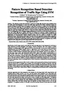
Aug 3, 1987 - bined in the construction of a plasticine model which describes the basic three-dimensional structure of SRP. The model is com- pared to ...
The EMBO Journal vol.6 no.11 pp.3471 -3477, 1987
Evidence for an extended 7SL RNA structure in the signal recognition particle
David W.Andrews', Peter Walter2 and F.Peter Ottensmeyer Department of Medical Biophysics, University of Toronto, and Ontario Cancer Institute, 500 Sherbourne Street, Ontario M4X-lL9, Canada and 2Department of Biochemistry and Biophysics, University of California, San Francisco, CA 94143, USA
'Present address: Department of Physiology, University of California, San Francisco, CA 94143, USA Communicated by B.Dobberstein
The signal recognition particle (SRP) functions in conjunction with the SRP receptor to target nascent ectoplasmic proteins to the protein translocation machinery of the endoplasmic reticulum membrane. SRP is a ribonucleoprotein consisting of six distinct polypeptides and one molecule of 7SL RNA 300 nucleotides long. SRP has previously been visualized by a variety of electron microscopic techniques as a rod-shaped particle 24 nm long and 6 nm wide. We report here microanalysis by electron spectroscopic inaging which localizes the RNA molecule in SRP to primarily the two ends of the particle. These results suggest that the single 7SL RNA molecule spans the length of the particle. Micrographs from a scanning transmission electron microscope pernit visualization of unstained SRP with low electron exposure, as well as the direct measurement of the mol. wt of the particle. These micrographs confim our earlier suggestion that SRP is divided into three structural domains and allow discrimnination of the two ends of the structure. The results of both techniques have been combined in a model for the structure of SRP in which we propose the basic orientation of the 7SL RNA. The structure proposed is consistent with the secondary structure predicted for the RNA and with biochemical data. Key words: electron spectroscopic imaging/signal recognition particle/scanning transmission electron microscopy/ ribonucleoprotein Introduction The signal recognition particle (SRP) functions as an adapter between the cytoplasmic protein translation machinery and the protein translocation apparatus associated with the membrane of the endoplasmic reticulum. Three classes of protein have been shown to use this translocation system. Two of these are proteins translocated across the membrane: secretory proteins (Palade, 1975) and lysosomal proteins (Erikson et al., 1981). The third class includes those proteins integrated into the membrane of the endoplasmic reticulum (Lingappa et al., 1978). To understand this complex system will require not only the elucidation of the sequence of events but also the functional role, composition and physical properties of the constituent macromolecular complexes. Here we describe one of these physical properties for one of the isolated complexes, the structure for SRP. The role of SRP in the sequence of events resulting in IRL Press Limited, Oxford, England
subcellular compartmentalization of secreted and integral membrane proteins appears to be one of targeting the nascent polypeptide to the membrane of the endoplasmic reticulum (as reviewed by Walter and Lingappa, 1986). SRP is a ribonucleoprotein particle of well-defined molecular composition. It is composed of one molecule of RNA 300 nucleotides in length, the 7SL RNA, and six polypeptides of mol. wts 9, 14, 19, 54, 68 and 72 kd (Walter and Blobel, 1980, 1982). These polypeptides are organized in SRP as four proteins. The 19- and 54-kd proteins exist as monomers while the 9- and 14- and the 68- and 72-kd polypeptides form heterodimers termed 9/14-kd and 68/72-kd proteins respectively. All of the proteins are present in SRP in equimolar amounts and the total apparent mol. wt is 300 kd. The particle, the component proteins and the RNA have all been isolated and highly purified (Walter et al., 1984). When separated, both the RNA and proteins have no demonstrable SRP activity by themselves, but can be reconstituted to form an active particle (Walter and Blobel, 1983a). In a previous examination of the structure of SRP, a rod shape was deduced from bright-field electron micrographs of negatively stained preparations and from dark-field micrographs of the particle critical-point-dried and unstained or shadowed with platinum-carbon (Andrews et al., 1985). In that report we also suggested that reproducible invaginations along the length of the particle appeared to divide SRP into three domains. As a control for the electron spectroscopic images used to visualize the 7SL RNA in SRP and to assess further the relevance of these micrographs to the unirradiated solution structure of SRP we have examined the particle with the low electron exposure possible in scanning transmission electron microscopy (STEM) and measured the mass of the structure observed. These micrographs confirmed our three-domain structure for SRP and mol. wt measurements provided an unambiguous means for determining the end-for-end orientation of the particle. The 300 nucleotide 7SL RNA in SRP has been sequenced and contains two stretches showing 80% homology to an Alu consensus sequence, one of - 100 nucleotides at the 5' end and the other of -50 nucleotides at the 3' end (Li et al., 1982; Ullu et al., 1982). The central region of the molecule termed the S sequence, is 150 nucleotides long, shows no homology to Alu DNA and is present in the genome at middle repetitive frequency. The sequence of the RNA suggests that the molecule is highly structured, being double stranded in many regions (Gundelfinger et al., 1984). This suggestion of order together with the fact that the RNA molecule accounts for more than one-third of the mol. wt of the particle suggested to us that the novel microanalytical technique electron spectroscopic imaging might provide information about the disposition of the 7SL RNA in SRP. Electron spectroscopic imaging allowed us to determine the in situ location of the 7SL RNA in SRP. By this technique the bulk of the RNA appears to be located in the two terminal domains of SRP. Combining our microscopic results with the known biochemistry of SRP permits preliminary assignment of the orientation of the RNA molecule within the particle. -
-
3471
D.W.Andrews et al.
Mr X 10-
$lo,
Fig. 2. Histogram of mol. wts of SRP.
Fig. 1. STEM dark-field electron micrographs of SRP. Picture element size is 10.1 A. Bar in overview, 50 nm; in gallery, 20 nm.
Results For biological complexes electron microscopy can routinely reveal structural details of the order of 2.0-3.0 nm. Interpretation of micrographs would be straightforward except that the necessarily hostile environment of the electron microscope can seriously perturb the structure of relatively fragile biomolecules. For microscopy of particles, their natural aqueous environment is removed, they may or may not be contrasted with heavy metals and then are subjected to high vacuum and to a beam of highenergy electrons.
3472
To localize the RNA in SRP using electron spectroscopic imaging requires that particles be examined unstained at relatively high electron exposure. We have shown previously that the structure of SRP in such images is similar to micrographs of negatively stained or platinum-carbon shadowed SRP (Andrews et al., 1985). To examine further the relevance of the relatively high electron exposure micrographs required for microanalysis we have examined SRP with the low electron exposure possible in STEM and measured the mass of the structures observed. Three-domain structure of SRP In Figure 1 STEM micrographs of freeze-dried SRP are presented along with enlargements of representative particles. These STEM dark-field images appear identical to those previously obtained for unstained SRP spread either with or without Nikkol and airdried or critical-point-dried (Andrews et al., 1985 and below). most of the views presented are of the more informative longitudinal orientation. However, oblique views and end views such as those reported with more conventional techniques are also observed as shown in the bottom row of Figure 1. Figure 2 is a histogram of the mol. wts measured for these particles. The mol. wt determined, 356 + 51 kd (SD), is indistinguishable from the 330-kd mol wt expected from molecular composition. Even a cursory inspection of the micrographs in Figure 1 indicates that the rod-shape previously deduced for SRP adequately describes the basic organization of the particle. A closer inspection reveals invaginations or crevices along the main axis of the particle which divide it into three domains (Figure 1, row 2). We first noted this potential division into domains in an examination of high-dose, dark-field electron micrographs (Andrews et al., 1985). That the domain structure is also recognizable in these low-dose images of freeze-dried particles increases our confidence in the relevance of these features. The invaginations appear to be hinge regions which confer a marked degree of flexibility to the complex (Figure 1, rows 5 and 6). The third or lower domain in the images narrows to a tail which extends the overall length of SRP to 26-28 nm. The widest por-
7SL RNA structure in SRP
Fig. 3. (a) 1 10-eV ESI, (b) 150-eV ESI, (c) P-IM of SRP. We have attempted to preserve the relative image contrast for all images. However, contrast alterations inherent in the printing process makes quantification from final figures difficult. Bar is 10 nm.
tion of this domain is 10 nm wide in some orientations, while at the narrowest point in the SRP images in the hinge region between domains 1 and 2, the structure is 3-4 nm wide. Although these features permit the two terminal domains to be distinguished visually in most micrographs of particles oriented longitudinally, the basic orientation SRP can be most easily established using the mass measurements obtained by STEM. If one simply bisects the particle in the middle of the center domain, by measuring - 130-140 am from either end, the mol. wt measured for one-half of the particle is - 30% greater than the other (140 versus 190 kd). This uneven distribution of mol. wt along the length of the particle is more evident if one uses our arbitrary division of the particle into three domains to estimate the mol. wt of each of the domains. The molecular weights obtained for domains 1-3 are 105 L 12 kd, 68 i 10 kd and 156 :1 11 kd respectively. For this estimation we chose 11 STEM dark-field micrographs in which the domains were clearly resolved. The mol. wt of the hinge regions was arbitrarily included with the terminal domains. For this reason the mol. wts for these domains may be slightly overestimated, nevertheless they serve as an unambiguous means to establish the orientation of micrographs of SRP. 7SL RNA localization The studies described above provide independent evidence, using a low electron dose technique, that our previous dark-field micrographs of unstained specimens accurately represent the structural organization of SRP. We have now extended the analysis of unstained preparations by using electron spectroscopic imaging to localize the RNA molecule within SRP. In this technique electrons that have lost a characteristic amount of energy by ionizing one of the inner-shell electrons of a particular element are used to map that element in the specimen. Ionization maps calculated for phosphorus (P-IMs) permit us to differentiate nucleic acids from protein within particles, because phosphorus is present almost exclusively in the phosphodiester bonds of the nucleic acid. For SRP, P-IMs calculated from electron spectroscopic images (ESIs) recorded above and below the L-shell ionization edge for phosphorus were used to localize the 300-nucleotide 7SL RNA within. Molecules of catalase (M, 250 kd) were included as an internal standard to correct for differences in photographic exposure, potential mass loss of molecules during electron exposure and to provide a reference that does not contain phosphorus. Catalase appeared to be ideal for this purpose because these molecules have a structure recognizably different from almost all of the orientations of SRP and contain no phophorus. In micrographs molecules of catalase appear circular and are
3 2 0 -1 Net Phosphorus (arbitrary units )
S29?P
Fig. 4. Histogram of signals recorded in P-IMs of SRP (solid line) and catalase (dotted line) from one pair of ESIs.
therefore easily distinguished from the rod-shaped longitudinal view but not end-on views of SRP. We were able to distinguish catalase molecules from end-on views of SRP by measuring the integrated optical density for all of the circular structures in the 110 eV reference ESIs. In these images, as in dark-field electron micrographs, integrated optical density (OD) is to a first approximation related to mol. wt. Therefore circular end-on views of SRP have the same integrated OD as rod-shape, while molecules of catalase integrate to only 75% of this density. Calculation of a P-IM from ESIs for one rod-shaped SRP is illustrated in Figure 3. The 1 10-eV reference ESI (Figure 3a) is normalized for photographic exposure and mass loss, aligned with and subtracted from the 150-eV phosphorus-enhanced ESI (Figure 3b) resulting in the P-IM (Figure 3c). To locate the phosphorus signal (i.e. the 7SL RNA) within the SRP structure two contour lines are calculated for the 150-eV ESI of the particle, between one and two SDs above the mean in the background carbon film. These contour lines are then displayed with the PIM superposed. The phosphorus signals, visible near both ends of this SRP, are much larger than the noise fluctuations in the background in the image (outside the contour lines). The signalto-noise ratio measured over the entire particle for such phosphorus signals from 34 P-IMs of SRP in longitudinal orientation was 7.5 3.3 and from eight end-on views was 9.7 + 3.2. The net phosphorus signal measured from P-IMs of all the structures observed in a single set of digitized ESIs is shown in Figure 4. In this graph structures have been classified as either rod-shaped (solid line) or circular (dotted line). The latter population consists primarily of catalase molecules; however, a small number of end-on views of SRP are also included, accounting for the skewed distribution of the signal. For this reason and because of the small size of the RNA, random fluctuations in measured net-phosphorus signal overlap the zero peak expected for catalase. Nevertheless it is very clear from these data that the average net-phosphorus signal for rod-shapes is significantly different from that measured for circular structures (calculated: P < 0.0001). P-IMs were calculated for > 200 structures from ESIs of SRP and catalase. Representative P-IMs for 36 of these structures are shown in Figure 5. As indicated by the contour outlines of the corresponding SRPs, most of the views presented are the longitudinal orientation as in Figure 1. Some of the contour lines in rows 1-3 delineate the three-domain structure for SRP described above for STEM micrographs. Oblique orientations and some of the bent conformations for SRP are illustrated in 3473
D.W.Andrews et al.
20
10
0
30
a
0
I
c
b
D3
P
-0
c
Fig. 5. Gallery of P-IMs for SRP (rows 1-5) and 10 nm.
catalase
(row 6). Bar is
rows 4 and 5. Catalase analyzed analogously does not contain detectable phosphorus (Figure 5, last row) and is now easily distinguished from the end-on views of SRP shown in the first three P-IMs in row 5. Because catalase does not contain phosphorus, signals in PIMs either localized within these molecules or in the surrounding carbon film (Figure 5, bottom row) result from quantum noise of imaging and from radiation-induced alterations which rearrange the substructure of the molecule and the carbon film during microscopy. In general, radiation-induced alterations appear to be more frequent at the edges of particles and in the background carbon film (D.W.Andrews, unpublished observations). Ultimately these effects establish the limit in the sensitivity of the technique. As expected, although noisy, the phosphorus signals in P-IMs of SRP are much more pronounced than the random signals in catalase molecules. Therefore it is not unreasonable to assume that the basic structure of the RNA moiety is represented with a degree of fidelity in these images. The images displayed in Figure 5 give the general impression that although some RNA (phosphorus) is detected in some images over most of the length of the particle, there is more in the first and third domains of SRP than the central region. The amount of RNA in the first and third domains is approximately the same, with the average signal of the first domain being 0.89 i 0.28 that of the third domain. Being close to the limits of this technique, the signals detected from SRP allow us to deduce global features of the organization of the RNA molecule, while the finer structural detail remains difficult to interpret. Unfortunately, improving the detectability of the RNA in SRP by signal averaging in two or three dimensions is precluded at pre3474
-i
0
20
10 Length,
30
nm
Fig. 6. Histograms of OD per unit length of (0.5 nm) in (a) 10-eV reference ESIs and (b) P-IMs. Average of the six particles in the first row of Figure 6 (solid line) and standard error of the mean (shaded area). (c) Secondary structure of 7SL RNA predicted from sequence, base-pair distance in areas predicted helix 0.31 nm.
sent by the flexibility demonstrated by the particle and the difficulty in assigning unambiguous angular orientations to the individual domains. It was possible to align, in a crude end-to-end manner, the longitudinal views of SRP in the first row of Figure 5 using the larger mol. wt measured for one end of SRP. Averages calculated from these images permit the presentation of phosphorus distributions more simply by reducing them to a histogram. In Figure 6 the distribution of phosphorus along the length of the particle is compared with the secondary structure predicted for the RNA from its sequence. In Figure 6a the total mass per unit length measured as OD from 1 10-eV ESIs for the SRPs in the first row of Figure 5 is presented as a solid line. The shaded area represents the standard error. The average phosphorus signal measured for the same particles is displayed similarly in Figure 6b. Although the graph in Figure 6b is expectedly noisy due to the relatively small signal-to-noise ratio of the individual images and to errors inherent in aligning particles, the bimodal distribution referred to above is apparent. The secondary structure predicted for the RNA in Figure 6c is consistent with our measured phosphorus distribution.
7SL RNA structure in SRP
Fig. 7. Comparison of model with (a) fixed-beam, dark-field electron micrographs, (b) STEM dark-field micrographs. Bar is 10 nm.
Discussion We have used electron spectroscopic imaging to examine the distribution of the 7SL RNA within SRP. To verify the structural details revealed by this technique we have also examined the particle using scanning transmission electron microscopy. The principle advantage of using STEM to image SRP is the low electron dose with which micrographs of unstained particles can be recorded. For SRP an exposure two orders of magnitude lower than required for tilt beam dark-field is possible. Lowering the dose that the specimen receives reduces radiation-induced structural alterations which ultimately destroy the particle. Such lowdose micrographs have been shown to represent accurately the known structure of a number of unstained macromolecules including fibrinogen (Mosesson et al., 1981) and glutamine synthase (Haschemeyer et al., 1982) at spatial resolutions between 2 and 5 nm. Molecular weight determinations by STEM have in general proven accurate to 10% over a wide range of mol. wt (Wall, 1979). Most relevant to the determinations here, measurements of nucleosomes which have both a similar total mol. wt and ratio of protein to nucleic acid were accurate to + 2% (Woodcock et al., 1980). The reproducible morphology observed with low-dose STEM dark-field combined with mass determina-
tions which indicate that SRP is intact allow us to interpret the images in Figure 1 and our earlier higher-dose electron micrographs with greater confidence. The results obtained here from STEM dark-field micrographs and from high-resolution dark-field micrographs have been combined in the construction of a plasticine model which describes the basic three-dimensional structure of SRP. The model is compared to selected micrographs in Figure 7. The micrographs in Figure 7a were obtained with a conventional electron microscope and are high-dose, high-resolution images. In Figure 7b the micrographs presented are low-dose STEM images. This model was designed to illustrate several features suggested by our micrographs. The particle, as shown, is comprised of three domains. One end of the particle is considerably more dense than the other. Thus images of particles can be oriented end-for-end. SRP is observed to adopt both extended and variously curved conformations. Both forms of the particle have been observed in all of the specimen preparations examined thus far including: negative stain; platinum-carbon shadowed; unstained; air-, critical-point- and freeze-dried. The various conformations for SRP can be accounted for by permitting some flexibility between the domains. This flexibility, particularly evident in Figure 8b, necessitated only minor alterations in the model. Most of the resemblance observed results from rotating the model around its main axis. Although we cannot exclude the possibility that either the curved or the extended form is a direct or indirect result of the specimen preparation, the ubiquitous appearance of both forms in all specimen preparations argues that some flexibility is an inherent property of the particle. The similarity of the structures obtained in STEM low-dose micrographs and those obtained previously using relatively highdose, dark-field techniques (compare the images in Figure 7a with those in Figures 1 and 7b) demonstrate that the alterations that take place caused by either dehydration or irradiation do not seriously alter the basic (2 nm) organization of SRP. This encouraging result suggested that high-dose microanalytical techniques such as electron spectroscopic imaging could potentially be used to locate the RNA molecule in SRP. The high electron exposures required for microanalysis have generated concern over the extent to which structure can be interpreted from the resulting elemental distributions. Compared to the standard microanalytical approach, X-ray microanalysis, electron spectroscopic imaging is a relatively low-dose technique (see Materials and methods). While radiation damage with such microanalytic techniques is unavoidable, comparison of the structures otained for SRP over the range of electron exposures used here (Figures 1 and 8b, low exposure; Figures 3, 5 and 8a, high exposure) suggest that the electron exposure required for electron spectroscopic imaging has not seriously perturbed the structure of SRP. Moreover, electron spectroscopic imaging has already been used successfully to visualize the DNA in nucleosomes within chromatin (BazettJones and Ottensmeyer, 1980) and isolated core particles (Harauz and Ottenmeyer, 1984). RNA has been imaged in ribosomal subunits (Korn et al., 1983) while tRNA and 5S ribosomal RNA have each been detected in ribonucleoprotein particles (D.W.Andrews et al., unpublished). The distribution of phosphorus (RNA) within SRP measured from P-IMs, suggests that the bulk of the 7SL RNA molecule is located in the two terminal domains. The phosphorus distribution of the SRPs in one row of Figure 5 is depicted in Figure 6b along with the mass distribution (Figure 6a) and the current model for the secondary structure of 7SL RNA (Figure 6c). The orientation of the RNA molecule was deduced as described
3475
D.W.Andrews et al.
below. The predicted structure is phylogenetically conserved from insects to human and is therefore presumed to reflect the base pairing interactions in 7SL RNA with some accuracy (Siegel and Walter, 1986). In this model the RNA folds into a long stem such that the 5' and 3' ends are in close proximity. To facilitate comparison in Figure 7 the 7SL RNA has been drawn to the same scale as the micrographs by assuming 0.31 nm per base-pair of a helix in the double-stranded regions. The distance between basepairs in the single-stranded regions is drawn to the same scale but may be either larger or smaller. It is interesting to note that based on these studies the predicted secondary structure of 7SL RNA may actually reflect features of the tertiary structure of the molecule. The prominent stem in the secondary structure probably runs along the length of the particle between the first and third domains. The increased phosphorus signal measured in the ends of the particle is consistent with a more complex folded RNA structure in these domains. These results are complemented by data that were accumulated by biochemical and functional dissection of SRP and together with the micrographs presented here can be used to speculate on the molecular organization of the particle. We postulate that the 7SL RNA forms an extended stem structure which serves as a backbone for the assembly of SRP. To orient the RNA in the particle we made use of STEM mol. wt measurements for the particle and data that were generated by nucleolytic digestion of SRP. In particular, micrococcal nuclease digestion of SRP generates a subparticle SRP(s) containing the 'S' segment of the RNA together with the three higher mol. wt SRP proteins (19 kd, 54 kd, 68/72 kd) (Siegel and Walter, 1985). The 68/72 kd protein alone accounts for >30% of the mass of the particle. It follows directly that the bulk of SRP mass is associated with the S segment of 7SL RNA. Therefore in Figure 6 we have illustrated the 7SL RNA secondary structure with the S segment near the high mol. wt end of the particle. The rather extended structure we propose for SRP is consistent with the notion that SRP may be able to bridge the distance between the site on the ribosome where the signal peptide emerges, the nascent chain exit site and the site of peptidyl transferase activity, where SRP-mediated elongation arrest is likely to occur. It is an intriguing possibility that the Alu homologous RNA moiety, localized primarily in domain 1 of our model, might function to disrupt elongation by virtue of its conformation. For example, this part of the RNA molecule might interfere with the tRNA binding at the transferase site on the ribosome. Many other questions about the structure and function of SRP also remain unanswered. Yet the microscopic and novel microanalytical tools used here provide a new approach that is beginning to contribute to our understanding of the complex interactions involved. Materials and methods Preparation of SRP
Specimens were supported on thin carbon films - 2 nm thick. The preparation of these films has been described for STEM (Mosesson et al., 1981) and for electron spectroscopic imaging (Whiting and Ottensmeyer, 1972). SRP was purified to homogeneity as previously described (Walter and Blobel, 1983). To stablize SRP activity, we included Nikkol (a non-ionic detergent: octaethyleneglycol monododecyl ether; Nikko, Tokyo, Japan) in all buffers (Walter and Blobel, 1983b). SRP, stored at a concentration of 200-350 itg/ml in 12% wt/vol sucrose, 0.01 % Nikkol, 500 mM potassium acetate, 5 mM magnesium acetate, 1 mM dithiothreitol, 50 mM triethanolamine at pH 7.5 was diluted to a concentration of 2-10 sg/ml with 1 mM magnesium acetate, 0.002% Nikkol, 0.2 mM dithiothreitol, 10 mM triethanolamine pH 7.5. Samples were centrifuged at 10 000 g for 10 min and applied to grids by injection (Mosesson et al., 1981) at a final concentration of 1-5 Lg/ml. The STEM samples were freeze-
3476
dried and transferred to the microscope under vacuum (Mosesson et al., 1981). In one experiment the Nikkol was removed from SRP by omission from the final sucrose gradient purification step. When these particles were spread without detergent and freeze-dried an elongated structure resulted which was of too low mol. wt and without reproducible morphology. For these reasons such images were not analyzed further. Scanning transmission electron microscopy Before samples were applied to grids a solution of Tobacco Mosaic virus particles in distilled deionized water was applied. Grids were examined at the Brookhaven STEM resource facility (Brookhaven National Labs, Long Island, NY). Operation of this microscope to obtain low-dose, dark-field micrographs and mass determinations have both been described previously (Wall, 1979). Lowdose, dark-field images were recorded at an incident dose of 300-400 or 1200-1400 e/nm2 corresponding to pixel sizes of 0.203 nm and 0.101 nm respectively. To determine mass from these micrographs the electron scattering intensities were integrated over an area bounded by the particle minus a background obtained by averaging scattering from areas not containing particles. Tobacco Mosaic virus was used as internal standard and largely compensates for mass loss during imaging (Mosesson et al., 1981). Electron spectroscopic imaging After SRP was absorbed to carbon films a solution of 10% ethanol/10% glycerol containing 2.5 jtg/ml catalase was applied to samples to be used for electron spectroscopic imaging. These samples were washed with distilled deionized water and allowed to dry in air. Electron spectroscopic images (ESIs) were recorded at energy losses of 150 + 6 eV (phosphorus enhanced) and 110 A 6 eV (reference) using a Siemens Elmiskop 102 transmission electron microscope modified by adding an imaging electron energy filter (Ottensmeyer and Andrew, 1980). The electron optical magnification was x32 000 calibrated at an accelerating voltage of 80 keV. The acceptance angle of the imaging electron spectrometer was 15 mradian. Electron image plates (Kodak) were exposed to a developed OD of -0.4 under standard developing conditions for intermediate grain size. These glass plates were digitized as square arrays using a microdensitometer (Perkin Elmer, Model 11OA), each picture element corresponding to 0.25 nm2 in the micrograph. The characteristics and imaging properties of electron spectroscopic imaging have been presented previously (Ottensmeyer, 1984). To localize an element in a micrograph requires at least two ESIs. One is a reference image recorded at an energy loss below that of a specific inner-shell ionization edge for the element being analyzed. The other is recorded above this ionization edge, and its intensity is therefore enhaed in the image at every location containing the element. Normalization and subtraction of a 1 10-eV reference micrograph from a 150-eV phosphorus-enchanced micrograph results in a phosphorus ionization map (P-IM) for the specimen. Technically, such normalization with a reference image recorded at a single energy loss does not correct for potential changes in the slope of the background with energy loss. Nevertheless, the error introduced over the 40-eV range used here can be estimated from the elemental composition of the specimen and published background slopes. The slope of the background in electron energy loss spectra is usually modelled as I = AE R, where I is the intensity at the energy loss E (Egerton, 1982). The constants A and R can be measured for different elements from published reference spectra (Ahn and Krivanek, 1983). The fractional error due to extrapolation from a reference image at a single energy is given by: AE AR -1 (1 +E ) (e.g. 110 eV) and AE is the edge ionization the Where E is the energy below change in energy between the reference and the ionization images. A change of the slope of the spectrum of AR = 0.30 for phosphorus and carbon results in an expected underestimation of - 10% at 150 eV when a single 1 10-eV ESI is used as reference. Control experiments illustrating the negligible effect of specimen thickness variations on normalization have been presented elsewhere (Korn et al., 1983). For approximately half of the P-IMs calculated, reference ESIs at 110 eV were recorded before as well as after the phosphorus-enhanced 150-eV ESI. The photographic exposure of these images was normalized using areas of empty carbon film present in each image. In addition, curves depicting the change in integrated OD measured for catalase molecules in all three exposures were used to correct for potential differences in the rate of mass loss between the carbon film support and the macromolecules during electron exposure. The incident electron exposure to the sample is - 8 x I0 and - 24 x I04 e/nm2 for the 1 10-eV and 150-eV exposures respectively. This exposure to image phosphorus is large for electron microscopic imaging, but for a microanalytical technique it is - 20 times smaller than that used for X-ray microanalysis. Control experiments showed that the ratio of integrated OD of catalase molecules to SRP was the same in both 110-eV expo sures, indicating that the rate of mass loss is equivalent for SRP and catalase. Catalase does not contain phosphorus. Its change in mass could therefore be used
7SL RNA structure in SRP to deduce the change in mass for SRP in the phosphorus-enhanced 150-eV image. By assuming that mass loss is from the molecules alone, the average density of the carbon film can be used to correct for photographic exposure between images. Using this approximation the average mass loss measured for catalase between exposures is - 12 A 8%. To reveal systematic changes in the ESIs that are independent of energy loss one-half of the P-IMs were obtained from sets of ESIs in which the 150-eV image was taken first. No such change was observed. Fixed-beam, dark-field, electron microscopy Micrographs were taken on a Philips EM 300 electron microscope at 80 keV at nominal magnifications of x 31 000 or x 39 900 and exposures to the specimen of 8 x 10⁴ and 15 x 104 e/nm2 respectively. Operating conditions for highresolution, dark-field electron microscopy of SRP on this microscope have already been described (Andrews et al., 1985). Micrographs were printed directly from the glass plates. Image processing The data obtained from the STEM were stored directly in digital form as intensity of electron scattering as a function of position over the grid. Image processing for photography and mass analysis of STEM images has been described previously (Hainfeld etal., 1982). Digitized ESIs were aligned to within 1 part in 512 using an interactive computer display system. With such alignment no relative movement could be detected between widely separated structures when the same image areas taken at different energy losses were presented in rapid succession. Calculated P-IMs were smoothed to 1.5-nm resolution to reduce noise in the image by box convolution with a 3 x 3 element filter before the contour lines were calculated. Signal-to-noise ratios were calculated for the P-IMs by measuring the total integrated phosphorus signal in a rectangular area of the image large enough to contain more than entire putative molecules and by measuring the background fluctuations in several adjacent areas (typically 6-9) of the same dimensions. The relative amount of phosphorus in different domains of SRP was measured using corresponding smaller rectangular areas. For photography of some micrographs the number of picture elements was doubled by linear interpolation and then the image was smoothed by box convolution with a 2 x 2 element filter to reduce the visually disturbing effect of square image elements. This process is very effective with a cost in resolution of a barely noticeable 10% and a slight reduction in image contrast which was easily regained by electronic contrast enhancement of the displayed image.
Lingappa,V.R., Katz,F.N., Lodish,H.F. and Blobel,G. (1978) J. Biol. Chem., 253, 8667-8670. Mosesson,M.W., Hainfield,J., Haschemeyer,R.H. and Wall,J.S. (1981) J. Mol. Biol., 153, 695-718. Ottensmeyer,F.P. (1984) J. Ultrastruct. Res., 88, 121-134. Ottensmeyer,F.P. and Andrew,J.W. (1980) J. Ultrastruct. Res., 72, 336-348. Palade,G. (1975) Science, 189, 347-358. Siegel,V. and Walter,P. (1985) J. Cell Biol., 100, 1913-1921. Siegel,V. and Walter,P. (1986) Nature, 320, 81-84. Ullu,E., Murphy,S. and Melli,M. (1982) Cell, 29, 195-202. Wall,J. (1979) In Hren,J.J., Goldstein,J.I. and Joy,D.C. (eds), Introduction to Electron Microscopy. Plenum Press, New York, pp. 333-342. Walter,P. and Blobel,G. (1980) Proc. Natl. Acad. Sci. USA, 77, 7112-7116. Walter,P. and Blobel,G. (1981) J. Cell Biol., 91, 557-561. Walter,P. and Blobel,G. (1982) Nature, 299, 691-698. Walter,P. and Blobel,G. (1983a) Cell, 34, 525-533. Walter,P. and Blobel,G. (1983b) Methods Enzymol., 96, 682-691. Walter,P., Ibrahimi,I. and Blobel,G. (1981) J. Cell Biol., 91, 545-550. Walter,P., Gilmore,R. and Blobel,G. (1984) Cell, 38, 5-8. Whiting,R.F. and Ottensmeyer,F.E. (1972) J. Mol. Biol., 67, 173-181. Woodcock,C.L.F., Frado,L.-L.Y. and Wall,J.S. (1980) Proc. Natl. Acad. Sci. USA, 77, 4818-4822.
Received on June 10, 1987; revised on August 3, 1987
Acknowledgements Special thanks are due Dr Joseph Wall for help with the STEM analysis and for critical reading of the manuscript; and to his colleagues at the Brookhaven National Laboratories including Kristin Chung for grid and EM sample preparation, Frank E.Kito for STEM operation and Paul S.Furcinitti for help in computer analysis. We also thank Elizabeth Macpherson for technical assistance in preparing the specimen supports, Stuart Rose and Brad Frankland for help with the computer programming, and the Dunlap Observatory for use of the scanning microdensitometer. The work was supported by the Ontario Cancer Treatment Foundation, the National Cancer Institute of Canada, and grant MT-3763 from the Medical Research Council of Canada. Support for the Brookhaven STEM is provided by the NIH, Grant no. RR01777 and the US DOE. D.W.A. is a recipient of the Mary Beatty Scholarship.
References Ahn,C.C. and Krivanek,O.L. (1983) EELS Atlas, HREM Facility. Arizona State University, Tempe. Andrews,D.W., Walter,P. and Ottensmeyer,F.P. (1985) Proc. Natl. Acad. Sci. USA, 82, 785-789. Bazett-Jones,D.P. and Ottensmeyer,F.P. (1980) Science, 211, 169-170. Egerton,R.F. (1982) Ultramicroscopy, 9, 387-390. Erikson,A.H., Conner,G.E. and Blobel,G. (1981) J. Biol. Chem., 256, 11224- 11231. Gundelfinger,E.D., Krause,E., Melli,M. and Dobberstein,B. (1983) Nucleic Acids Res., 11, 7363-7374. Gundelfinger,E.D., Carlo,M., Zopf,D. and Melli,M. (1984) EMBO J., 3, 2325-2332. Hainfield,J.F., Wall,J.S. and Desmond,E.J. (1982) Ultramicroscopy, 8, 263 -270. Harauz,G. and Ottensmeyer,F.P. (1984) Science, 226, 936-940. Haschemeyer,R.H., Wall,J.S., Hainfield,J. and Maurizi,M.R. (1982) J. Biol. Chem., 257, 7252-7253. Korn,A.P., Spitnik-Elson,P., Elson,D. and Ottensmeyer,F.P. (1983) Eur. J. Cell. Biol., 31, 334-340. Li,W.Y., Reddy,R., Henning,D., Epstein,P. and Busch,H.J. (1982) J. Biol. Chem., 257, 5136-5142.
3477