ScienceAsia 28 (2002) : 153-159
Recovering of Copper from Synthetic Solution in 3PE Reactor Mali Hunsoma, *, Hugues Vergnesb, Patrick Duverneuilb, Kejvalee Pruksathorna, Somsak Damronglerda a
Department of Chemical Technology, Faculty of Science, Chulalongkorn University, Bangkok 10330, Thailand. b INPT1 ,ENSIACET2, 18 Chemin de la Loge, 31078 Toulouse Cedex, France. 1 Institut National Polytechnique de Toulouse, Place des Hauts-Murats, 31006, Toulouse cedex, France. 2 Ecole Nationale Supérieure des ingénieurs en Arts Chimiques et Technologies, Chemin de la Loge, 31078 Toulouse, France. * Corresponding author, E-mail:
[email protected]
Received 8 Jun 2001 Accepted 2 Nov 2001
ABSTRACT Recovery of copper from a synthetic solution with an initial copper concentration 1 g/l, pH 1 was investigated in a Pulsed Porous Percolated Electrode reactor (3PE). This reactor was constructed in the axial field configuration with 0.2 m diameter and 0.35 m height. Graphite particles were used as a voluminal cathode and a counter electrode made of titanium coated with ruthenium oxide was placed 0.04 - 0.05 m above the upper level of carbon particles. The optimum current intensity was obtained at 9 A at which more than 90 % of copper was recovered in 4 hours. Due to a current intensity drop during the destabilization of the granular bed, the recovery rate of copper decreased when the pulse frequency increased. In addition, a reasonable operating cost was obtained at about 14.87 FF/m3 (1.97 US$/m3) at optimum current. A dimensionless number, which shows the relationship between the mass transfer coefficient and flow rate of the electrolyte, was defined. KEYWORDS: Copper, Recovery, 3PE reactor, Electrodeposition technique.
INTRODUCTION Metals contamination in processed water is a serious problem for several industrial sectors such as surface treatment, electroplating and the electronics industry. The outlet wastewater from these industrial processes normally contains a metal concentration higher than the acceptable limit set by law. Therefore, the treatment of contaminated water before it is directly discharged is required in order to reduce the amount of metal to an acceptable level. The prospect of recovery has attracted interest among industries for environmental and economic reasons. For example, valuable heavy metals are recycled and reused while the outlet water is permitted to discharge to the environment. Many previous studies have attempted to find reasonable ways to recover heavy metals. Electrochemical process has low sludge production, low start-up and operating cost, no chemical contamination in the treated water, and high recovery of separated metals and processing materials. A multi-stage process has been investigated to recover heavy metals of Cu, Ni and Cr.1-2 Metal contaminated wastewater was first treated biologically, then by an acid leaching treatment and finally by
an electrochemical treatment. Armstrong3 reported the feasibility of selective electrodeposition of cadmium, cobalt, and nickel from a binary mixture as ~99 % pure metals. They pointed out that Cd(II) could be electrodeposited from a solution containing Cd(II) and Co(II) or Ni(II) without codeposition of Co and Ni. The electrodeposition process is carried out utilizing a three-dimensional electrode for its high active surface area per unit volume and high efficiency in mass transfer. Panizza4 used a copper foam electrode to remove copper from industrial effluent in an undivided mono-polar cell. The percent removed was greater than 98 % with a flow rate 1000 l/h at current intensity of 750 A. In other work by Polcara5, a recirculating batch reactor consisting of carbon felt electrodes held on an anionic exchange membrane was used to remove and recover heavy metal pollutants. About 90 % of the mercury was deposited on the electrode surface. Concentrations of copper and lead were reduced from 50 ppm to 0.05 ppm with 42 % current efficiency at -300 mV/SCE (Saturated Calomel Electrode) for copper and from 100 ppm to 1 ppm with 25 % current efficiency at -600 mV/SCE for lead.
154
A new type of electrochemical reactor named 3PE reactor (Pulsed Porous Percolated Electrode) was patented and constructed on an industrial scale.6-7 Fenouillet et al8 used this reactor in the axial field configuration to recover copper. Copper had been recovered until its final concentration was lower than 2 ppm. Reussard et al9 demonstrated the removal of chromium in 3PE reactor with a radial field configuration. They pointed out that the pH changed versus time during electrolysis and 100 % conversion was reached with controled pH. Aguirre et al10 described results of metal recovery from electroplating effluent in 3PE reactor. They found that the percentage of recovered copper, zinc and nickel was about 99, 93 and 80 % in 9, 13 and 16 hr, respectively. This paper describes the effect of parameters (current intensity, pulse frequency, cathode type and flow rate of solution) on copper recovery in 3PE reactor. A synthetic solution was used to eliminate other parameters. The effect of potential between working and reference electrodes was not studied because in industry the operating control is more difficult. A dimensionless number for this system was developed to describe the functioning of the reactor.
ScienceAsia 28 (2002)
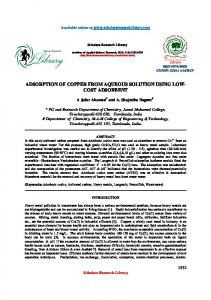
at the terminals of the electrode. The metal ions in solution are reduced to the metallic state and deposited onto the surface of the particles which face the anode (during (1-ξ)τ period) as shown in figure 1. The behavior of particles at this moment is similar to a fixed bed. When the air pulsation is applied, good contact between fluid and particles is obtained. The metalcoated particles, which have high density and weight, fall to the bottom of the reactor by force of gravity and are replaced by new particles during the destabilization period, ξτ. The behavior of these particles during this time period resembles a fluidized bed. Mass transfer in 3PE reactor The assumption of material balance is that a wellmixed condition is obtained in the batch reactor, see Figure 2. Material balance of component i in the reactor is expressed by.11 QCiE
=
QCiS + γA
(1)
MATERIALS AND METHODS The 3PE reactor can be considered as a compromise between fixed and fluidized bed reactors. It is composed of four components10: A. A solid matrix, composed of particles that act as voluminal cathode in contact with the current feeder. B. A counter electrode or anode having a small geometrical surface area. The material used must be resistant to oxidizing conditions. Platinum or titanium coated with ruthenium oxide are good choices. C. A circulation pump is used to circulate the electrolyte in the system through the granular bed. Two advantages of this are the renewal of the solution around the particles and structural improvement of the metal layer deposited. D. A pulsating system creates movement of the granular bed in the reactor forcing the movement of metal-coated particles to the bottom of the bed and avoiding the problem of clogging. During the operation, when the current is applied through the solution, the potential gradient is created
Fig 1. The periodic destabilization of the graphite particles.
Fig 2. Diagram of apparatus.
155
ScienceAsia 28 (2002)
Q( CiE − CiS ) = γA =
j ηA nF
(2)
Given n = 1 and j = nFkLCiS, then, j A nF = k L AeVe CiS
Sherwood number Sh =
Q( CiE − CiS ) =
Schmidt number Sc =
dCiS dt
(4)
The equation (4) can be written as dCiS dt = k L AeVe CiS
(5)
Rearrangement of equation (5), then gives
(6)
We then integrate (equation (7)) to obtain equation (8). k A V t dC iS = − L e e ∫ dt VS 0 C0 C iS
Ct
∫
ln
k AV Cit = − L e e t Ci 0 VS
kL d p D
µ ρD
(9)
(10) (11)
The relationship between these three dimensionless numbers can be expressed by the following equation b
Sh = a Re p Sc c
(12)
where a, b and c are constant. Generally, the value of c is assumed at about 0.25 in the volumetric electrode process.
EXPERIMENTAL
Q( CiE − CiS ) = − VS
k A V dCiS = − L e e dt CiS VS
ρd p v µ
(3)
If the storage tank is considered as a continuous stirrer tank reactor, the concentration evolution is a function of operating time. The material balance in the storage tank can be expressed by Q( CiS − CiE ) = VS
Reynolds number Re p =
(7)
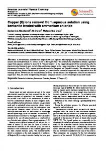
Experiments were performed at laboratory scale and 25 °C with a synthetic solution of copper. The synthetic copper solution, with total volume of 15 litres, was prepared with CuSO4.5H2O (98 % purity, Fluka Chemica) and adjusted pH by conc.H2SO4 (BDH Laboratory Supplies) to pH = 1 for each experiment. The experimental pH of the solution was set equal to 1 in order to eliminate the effect of high pH at the cathode where the evolution of H2 takes place. The physical properties of copper solution were obtained from the Handbook of Electrolyte solution Part A.12 The diffusion coefficient was 5.89x10⁻¹⁰ m2/s and the value of density and dynamic viscosity were 1005.6 kg/m3 and 9.29x10⁻⁴ kg/m-s; hence, the Schmidt number was about 1568. The experimental set-up is shown in Figure 3. The 3PE reactor was constructed in the axial field configuration about 0.2 m in diameter and 0.35 m in height. 0.5 kg of graphite particles, 0.0035 m
(8)
From equation (8), the value of mass transfer coefficient (kL) can be calculated from the slope of the plot between ln(Cit/Ci0) and time. Dimensionless number in 3PE reactor A dimensionless number which shows the relation between flow rate of electrolyte, mass transfer coefficient, and fluid properties, is expressed in terms of Reynolds numbers of the particular bed, Rep, Sherwood number, Sh, and Schmidt number, Sc.
Fig 3. Experimental set up of 3PE reactor with axial field configuration.
156
ScienceAsia 28 (2002)
diameter, 1690 kg/m3 density, and 1,000 m2/m3 total surface area per unit volume were used as the cathode because Aguirre10 has tested and demonstrated that the best support for metal deposition are graphite particles used in energy production. A counter electrode or anode made of titanium and coated with ruthenium oxide was placed above the upper level of particles by about 0.04 – 0.05 m to keep the cell voltage within the range of power supply. Its terminal was connected to a regulated power supply type PNT 32-40 (Heizinger). One magnetic pump type MD20R (Iwaki) was used to circulate the electrolyte between the storage tank and reactor. The pulsation of the system was conducted by an automatic controller of air (apparatus number 8-11 in figure 3). The operation of this controller was similar to a sinusoidal wave. The process was operated in galvanostatic mode (constant current). The solution was sampled every 2 hr until more than 99 % of copper was recovered. The concentration of copper in the samples was measured by a type (AA-275 Varian) Atomic Absorption Spectrophotometer . The parameters studied were current intensity (5 - 11 A), flow rate of electrolyte (3 - 8 l/min), pulse frequency (0.16 - 0.43 Hz), cathode type (graphite and graphite covered by copper). The amplitude of pulse was fixed at 0.025 m in order to investigate the effect of other parameters.
shown in Figure 4. The electrolysis time decreased when the applied current intensity increased up until 9 A. After that, it had no effect on electrolysis time. Figure 5 presents the correlation of current efficiency and operating cost as a function of current intensity. The operating cost was calculated by equation (15) after 99 % recovery. The results show that copper is recovered with high efficiency in a 3PE reactor. Copper ions in solution were reduced to the metallic state and deposited on the surface of graphite particles. The optimum current intensity was obtained at 9 A with more than 90 % recovery in 4 hours and about 35 % of current efficiency. A minimum operating cost of about 14.87 FF/m3 (1.97 US$/m3) was obtained at the optimum current intensity. Pulse Frequency The effect of pulse frequency was tested at constant flow rate of electrolytes. Pulse frequencies were varied between 0.16 - 0.43 Hz for copper with
Calculation of some parameters Percent recovery and current efficiency can be calculated by the following equation.
% recovery =
(W
i
− Wt
Wi
% current efficiency =
Operating cost =
) x 100
(13)
Fig 4. Percent recovery versus time of copper solution 1 g/l, pH = 1.
nFWi (% recovery ) (14) MW ( it )
itVCu VT
(15)
RESULTS AND DISCUSSION Optimum Current Intensity The current intensity was varied between 5 - 11 A at a constant flow rate of electrolyte (8.4 l/min) of synthetic copper solution with initial concentration of 1 g/l at pH = 1. The effect of current intensity is
Fig 5. Current efficiency and operating cost versus current intensity of copper solution 1 g/l, pH = 1.
157
ScienceAsia 28 (2002)
initial concentration 1 g/l, pH = 1, flow rate 8 l/min, and 9 A of current intensity. The effect of pulse frequency is shown in Figure 6. Results show that when the pulse frequency is increased, the copper recovery rate decreases. This is because destabilization of the bed occurs disrupting the contact between particles and between particles and the current feeder. The current between the anodic and cathodic is hindered causing a drop in current intensity. Because of the better contact at low pulse frequency, a higher percentage of recovery is obtained. Although a high metal recovery is obtained at a pulse frequency of about 0.16 Hz, a bridge between adjacent particles is observed. If the experiment is performed at pulse frequency lower than 0.16 Hz, there is a problem with clogging. Experiments were not performed at a pulse frequency less than 0.16 Hz. Influence of Cathode Composition In previous experiments in which graphite particles were used as a cathode, copper ions reduced to metallic state were initially deposited on the graphite surface of the particles. After this point, the reaction was continuous as the metallic copper deposited on graphite already covered by copper. This is similar to deposition of copper ions on metallic copper. When the experiment was over, the graphite particles were refreshed by a rinse in nitric acid (HNO3, BDH Laboratory Supplies). In this case, experiments to determine the effect of cathode composition were conducted by cyclic voltammetry using a Potentiostat/ Galvanostat Apparatus Model 273. Graphite and copper rotating disc electrodes were used as the cathode and platinum was used as the anode. The polarization curve showed that the copper cathode consumed an applied current intensity 3 times higher than the graphite cathode. Therefore, the deposition of
Fig 6. Percent recovery versus time of copper 1 g/l, pH = 1, i = 9 A.
copper on a copper surface seemed to be higher than on a graphite surface. However, in a 3PE reactor, the results of concentration evolution with two types of cathode surface (graphite and graphite covered by metallic copper) indicated that the concentration evolution of copper on the two types of cathode had the same behavior. Copper ions in solution were completely recovered in about 7 hours. It can be concluded that the surface composition had no affect on the copper deposition process. In this study, with the applied current intensity being greater than the limiting current intensity, there was a sufficiency of charge to deposit on both surfaces. Flow Rate of Solution The experiments of copper 1 g/l, pH = 1 at optimum current intensity (i = 9 A) were performed at different flow rates (3 - 8 l/min). Figure 7 shows the results of these experiments. The percent recovery increased with flow rate because the higher the flow rate, the higher the mass transfer of metal species present. The mass transfer coefficient, kL, for each flow rate was determined by equation (8). The concentration included in this determination ranged between 50 - 1,000 mg/l because the atomic absorption spectrophotometer gave low precision at very low concentration. The results indicated that when flow rate increased, kL increased. Following these results, a dimensionless number that shows the relationship between the mass transfer coefficient, flow rate of electrolyte, and physical properties of solution was developed in terms of the Sherwood number according to equation (12). It can be expressed by the following equation. Sh = 1.20 Re p
0.411
Sc 0.25
Fig 7. Percent recovery versus time of copper 1 g/l, pH = 1, i = 9 A.
158
When 6 < Rep < 16 and Sc = 1568. This dimensionless number is useful for describing the functioning of the reactor and for the scale up of the reactor in further work. V. Comparison with other works Figure 8 shows a comparison between our work and the literature.13-14 Both researchers used an electrochemical technique. The copper recovery system of Olive and Lacost13 used a flow through porous electrode with spherical particles covered with copper and percolated by a dilute sulfuric acid solution of copper ions. Karabelas14 used a packed bed reactor to find the mass transfer by using potassium ferrocyanide and potassium ferricyanide. The results showed that the mass transfer in this work agreed well with these previous studies. The differences may result from the different chemical substances used and the system.
CONCLUSION From this study, copper ions in synthetic solution were recovered with good efficiency. Optimum current intensity was found at 9 A, at which more than 90 % of copper was recovered in 4 hours. The current efficiency was about 35 % at 90 % recovery. The lowest operating cost was obtained at current intensity of 9 A with about 14.87 FF/m3 (1.97 US$/ m3) of treated solution. Low pulse frequency gave a better percentage of recovery than high pulse frequency due to a current intensity drop during the destabilization of granular particles in the reactor. Cathode composition, graphite or graphite covered by metallic copper, did not affect the concentration evolution behavior due to the applied
Fig 8. Comparison between our dimensionless number and literature.
ScienceAsia 28 (2002)
current intensity higher than limiting current intensity. In both cases, the complete recovery was achieved in 7 hours. Mass transfer coefficients were strongly affected by flow rate of electrolyte. They increased when flow rates increased. The novelty of this work is the use of an air pulsation system, which prevents clogging by granules and the use of material having high specific surface area as cathode. In addition, a dimensionless number, which shows important relationships regarding reactor functioning was reported. This Reynolds number range is different from the other previous works.
ACKNOWLEDGEMENTS The authors would like to thank the Thailand Research Fund and the Embassy of France in Thailand for the financial support to our project. Nomenclature A active area of cathode, m2 A = Ae Ve Ae specific surface area per unit volume of cathode, m-1, Ae = HpΩ CiE, CiS inlet and outlet concentration of species i, mol/m3 Cit concentration of species i at t, mol/m3 Ci0 intial concentration of species i, mol/m3 Cu cost of electricity per unit, (= 0.7 FF/kW-hr) D diffusion coefficient, m2/s dp particle diameter, m f pulse frequency, Hz F Faraday constant, 96500 A-s/equiv Hp height of cathode level, m i current intensity, A j current density, A/m2 kL mass transfer coefficient, m/s n number of electron involved in the system Q flow rate of solution, m3/s t electrolysis time, s U2+, U2- upward and downward final velocity, m/s Umf minimal particle fluidization velocity, m/s U0 permanent liquid velocity, m/s v velocity of electrolyte, m/s V voltage, volt Ve total particle volume, m3 VR volume of reactor, m3 VS volume of storage tank, m3
ScienceAsia 28 (2002)
VT Wi MW Wt
volume of solution in reactor and storage tank, m3, VT = VS + VR initial weight of metal, g molecular weight of metal, g weight of metal at time t, g
Greek characters ξτ time of destabilized bed, s (1-ξ)τ time of fixed bed, s γ rate of reaction, mol/s η current efficiency Ω cross sectional area of reactor, m2 µ liquid viscosity, kg/m-s ρ liquid density, kg/m3
REFERENCES 1. Pruksathorn K et al (1997) Recovery of Metals in sludge of Publicly Owned Treatment Works and Industrial Effluents. Franco-Thai Symposium on New Advance in Water and Wastewater Treatment, 281-95. 2. Pruksathorn K et al (1999) Removal of Metals in sludge of wastewater treatment. AIDIC Conference Series 4, 147-52. 3. Armstrong RD (1996) Selective Electrodeposition of Metals from Simulated Waste Solution. Journal of Applied Electrochemistry 26, 379-84. 4. Panizza M (1999) Electrochemical Remediation of Copper (II) from an industrial Effluent Part II: Three-Dimension Foam Electrode. Resources, Conservation and Recycling 27, 299-307. 5. Polcaro A M and Palmas S (1992) Flow-By Porous Electrode for Removal and Recovery of Heavy Metals Pollutants. ICHEME SYMPOIUM SEIES 127, 85-96. 6. Lacost G (1986) Procédé et installation d’électrolyte par percolation à travers une ou des électrodes volumiques poreuses. French patent Fr 86 08331, Toulouse, France. 7. Lacost G and Duverneuil P (1996) Nouveau type de réacteur à fonctionnement continu, complémentaire des procédés à Electrode Pulsée Poreuse Percolée (E3P). French patent Fr 96 03036, Toulouse, France. 8. Fenouillet B et al (1999) Metal Recovery in Surface Treatment Units by Using the 3PE Reactor. Environmental Engineering and Policy 1, 191-4. 9. Reussard S (1992) Removal of Hexavalent Chromium Converting to Chromium Hydroxide by Treatment in a Electrochemical Reactor. ICHEME SYMPOIUM SEIES 127, 97-109. 10.Aguirre P et al (1994) Recovery of Zinc, Copper and Nickel from Industrial Effluents Generated by the Electroplating Using The “3PE” Technology. Separation Processes: The Minerals, Metals & Materials Society, 257-68. 11.Lacost G (1991) Development of The Periodically Pulsed Porous Electrode. Electrochemical Cell Design and Otimization Procedures, Dechema Monogr 123, 411-25. 12.Department of Chemistry: University of Coimbra (1989) Handbook of Electrolyte Solution, Part A, VMM lobo, Elsevier, 14. 13.Olive H and Lacost G (1979) Application of volumetric electrodes to the recuperation of metals in industrial effluentsI). Electrochemica Acta 24, 1109-14. 14.Karabelas AJ (1971) Use of asymptotic relations to correlate mass transfer data in packed beds. Chemical Engineering Science 26, 1581-9.
159