imaging system that could see in every direction could play a key role in such a ..... vectors are u1 and u2 and that belong to a plane P characterized by its ...
Rectangle Extraction in Catadioptric Images Jean-Charles Bazin, Inso Kweon RCV Lab, KAIST 373-1 Guseong-dong Yuseong-gu Daejeon, Korea
Cedric Demonceaux, Pascal Vasseur CREA, UPJV 7, rue du Moulin Neuf, 80 000 Amiens, France
{jcbazin,iskweon}@kaist.ac.kr
{cedric.demonceaux,pascal.vasseur}@u-picardie.fr
Abstract Nowadays, robotic systems are more and more equipped with catadioptric cameras. However several problems associated to catadioptric vision have been studied only slightly. Especially algorithms for detecting rectangles in catadioptric images have not yet been developed whereas it is required in diverse applications such as building extraction in aerial images. We show that working in the equivalent sphere provides an appropriate framework to detect lines, parallelism, orthogonality and therefore rectangles. Finally, we present experimental results on synthesized and real data.
1. Introduction Any vision algorithm requires some pre-processing steps such as edge detection, line extraction or basic image enhancement. Whereas some satisfying methods have been developed for traditional perspective images, there exists a very little literature concerning such low-level processing for catadioptric vision. Our work focuses on rectangle detection in catadioptric images. To the best of our knowledge, this is the first paper dealing with this problem. We have to face many difficulties such as line extraction, parallelism and orthogonality, despite strong distortions inherent to catadioptric images. Previous works concerning perspective cameras can be divided into two groups. The first one deals with fronto-parallel views. In this kind of images, it is easy to extract parallel and orthogonal lines. Especially, we can cite [2][9][14] which are based on geometrical structure of peaks in the Hough transform. For example, parallel lines are characterized by a 90-degree offset for the theta parameter. The second category deals with general perspective images and most of algorithms are based on the estimation of vanishing directions. For instance, authors of [19] detect candidate rectangles by a simple line intersection method. And then, if the normalized fronto-parallel view of the candidate contains two dominant horizontal and vertical directions, the quadrangle is considered a rectangle.
978-1-4244-1631-8/07/$25.00 ©2007 IEEE
The four sides defining a rectangle must verify parallelism, orthogonality and length properties. As will be reminded in this paper, a line, and thus any rectangle sides, is projected as a great circle on the equivalent sphere. Therefore, detecting rectangles requires checking whether the four associated great circles verify rectangle properties (parallelism, orthogonality,…) in the sphere. Thus, we need a procedure that can detect whether two great circles correspond to two parallel, perpendicular or any lines in world space. In the same way that for traditional perspective images, developing such a procedure for catadioptric images is not trivial. That is why this paper is divided into many parts. After introducing catadioptric projection, we present our algorithm for line extraction and detection of dominant directions. Then our automatic rectangle detection algorithm for catadioptric images is explained and finally, we show how the knowledge of the plane normal facilitates the extraction of parallel and orthogonal lines.
2. Catadioptric vision and image formation Intuitively, the wider the field of view is, the more information a robot can gather from the environment. An imaging system that could see in every direction could play a key role in such a process. Such systems are called “omnidirectional systems” and provide a much wider field of view compared to traditional perspective cameras. Catadioptric sensors belong to the family of omnidirectional systems. They use both a mirror and a lens to form images through a conventional camera. Such systems usually have a field of view larger than 180 degrees and are getting both cheaper and more accurate. While they have long been used in telescopes (to focus light from stars onto the eye of the observer), only recently they gained in popularity together with other omnidirectional vision systems based on fish-eye lenses or clusters of outwards-looking cameras. Baker and Nayar classified catadioptric sensors into two categories depending on the number of viewpoints [1]. Sensors with a single viewpoint, named central catadioptric sensors, permit a geometrically correct reconstruction of the perspective image from the original catadioptric image. Geyer and Daniilidis [11] have demonstrated the
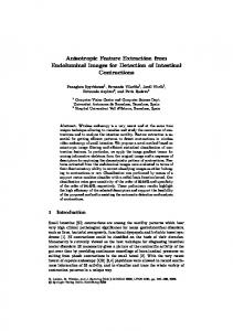
equivalence for the single viewpoint category with a two-step projection via a unitary sphere centered at the focus of the mirror (the single viewpoint) (Fig 1). This two-step projection consists first in projecting real 3D point Pw to point Ps from the center of the sphere Oc. The second step projects point Ps to point Pi in the image plane from point Op. In order to apply this equivalence, it is necessary to know the intrinsic parameters of the camera and two additional parameters namely ξ and φ which are respectively equal to distances |OcOp| and |OcOi| (Fig 1). Parameters ξ and φ define the shape of the mirror (see [3] for further details on their signification) and can be estimated by calibration. Whereas it does not seem obvious at the first sight, the sphere equivalence is interesting for many reasons. First, it greatly simplifies the formalism to take catadioptric distortions into account. Indeed, catadioptric images are highly distorted because of the mirror projection, which complicates the image analysis. Working in the sphere permits to manipulate those distortions much more easily. A second important reason is that it permits to work in a general framework, i.e. the sphere, independently on the fact that a hyperbolic or a parabolic mirror is used. Finally, the sphere space provides very interesting projection properties. For example, it is trivial to observe that a line is simply projected as a great circle in the sphere [11]. Therefore most of algorithms of line detection for catadioptric images are based on this important characteristic, especially the algorithm we develop in this paper.
higher than 240 degrees, which actually happens in most of real situations. Moreover, some conics detected in the image may actually correspond to entities that are not line in world space. The second group corresponds to the adaptation of Hough transform to the sphere space [15][17][18]. However this approach suffers from the same limitations as in perspective case such as computationally expensive and importance of parameters sampling. The third and last category is based on specific geometric constraints of paracatadioptric sensors and therefore cannot be applied to other catadioptric systems [4][16]. Thus, it appears that general, accurate and fast methods for line extraction in catadioptric images do not exist. That is why we have developed our own algorithm which can be seen as an extension of polygonal approximation of perspective case towards sphere space. The main idea is the following: after detecting edges in the image and building chains of connected edge pixels, we project them on the sphere and verify whether these chains verify the great circle constraint, that is to say whether they correspond to projection of world lines. For this, we apply a split and merge algorithm based on the distance between chain points and the plane defining a great circle.
3.1. Splitting criteria Let P1=(X1,Y1,Z1) and PN=(XN,YN,ZN) be two endpoints of a chain composed of N pixels. These two points define a unique great circle whose normal is
n = OP1 × OPN where O is the sphere center. We consider that a sphere point Ps=(Xs,Ys,Zs) of a chain belongs to a great circle whose normal is the vector n if: ( X s , Ys , Z s ).n ≤ SplitThres hold This chain is considered a line if at least 95% of the chain points belong to the great circle. At the contrary, we split the chain into two sub-chains at the point :
arg max ( X i , Yi , Z i ).n i
Figure 1: Equivalence between catadioptric projection and two-step mapping via the sphere (cf. text for more details)
3. Line detection for catadioptric vision Methods for extracting lines in catadioptric images can be divided into three groups. The first one aims to compute the conic that best fits the points in the image with respect to a certain metric [4][8][20]. All these conic-fitting-based algorithms obtain very bad results when the occlusion is
This splitting step stops when the chain is considered a line or the chain length is smaller than a certain threshold (NbPixels). This step provides a set of catadioptric lines in the image. However, this method may perform a multi-detection of one single line because of possible edge discontinuity. In order to overcome this limitation, we suggest merging the catadioptric lines based on a similarity measure.
3.2. Merging criteria Let d1 and d2 be two catadioptric lines detected by the above procedure. These two lines are characterized by the normals of their associated great circles, respectively n1 and n2. We consider that these two lines are similar if they define a same plane, that is to say:
1 − n1 .n2 ≤ MergeThreshold In this case, the two lines are merged in a single one. The equation of the new catadioptric line is computed from all the chain pixels of the two lines. Let note
(
M 1 = X i1 ,Yi1 , Z i1
)
(
M 2 = X i2 , Yi 2 , Z i2
i =1... N1
SplitTreshhold. Experiments on hundreds of images issued from many different video sequences have shown that lines can be extracted correctly and robustly (cf. Figure 2,4,5)[5].
)
i =1... N 2
the pixels of the catadioptric lines d1 and d2. Let M be the matrix of dimension (N1+N2)x3 :
X 11 1 X M = N21 X1 X N2 2
(
Y11 YN11 Y12 YN22
The normal vector n = n x , n y , n z
Z11 1 Z N1 Z12 2 Z N2
)
T
of the new great
circle is the solution of M .n = (0, …,0 ) . The solution of this system is obtained by SVD of the matrix M [13]. T
(a)
(c)
(b)
(d)
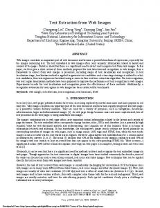
Figure 2 : The 4 main steps of our line detection algorithm : edge detection by Canny (a), edge chaining (b), and before (c) and after (d) the merging step.
3.3. Results In order to validate our algorithm, we have tested it on real catadioptric images. By using calibration parameters, the image is projected on the equivalent sphere. Then we detect lines by the great circle constraint in the sphere space. Obviously, the shorter the edge chain is, the more fragile the estimation of the great circle normal is. Therefore we suggest using a relative high value for
Figure 3 : Projection of two parallel lines d1 et d2 on the sphere as two great circles whose normals are n1 and n2.
4. Extraction of dominant directions In traditional perspective images, detecting parallelism and orthogonality is not an easy task. Most of methods are based on estimating the vanishing points thanks to extracted lines. However, because of the narrow field of view, the image contains very few lines and thus, the extraction of vanishing points, parallel and orthogonal lines is neither accurate nor robust. Concerning catadioptric vision, we show in this section that parallel and orthogonal lines belonging to dominant directions can be extracted robustly thanks to the wide field of view that permits to observe a much higher number of lines. As proved in [11], a set of parallel lines intersect in two antipodal points in the sphere. These two points correspond to the vanishing directions and can be characterized by a unit vector u. Therefore, the idea for detecting parallel lines consists in computing this vector u. For this, we apply the following algorithm. Let n1 and n2 be two normal vectors of great circles. Their intersection is calculated by u = n1 × n2 and corresponds to the direction of the antipodal points. Then we consider that a great circle normal ni is in the same direction than u if:
1 − ni .u ≤ SimilarityThreshold Doing the same way for each combination of two normals, we can compute the vector u that correspond to the highest number of parallel lines, that is to say lines composing the dominant direction, and the associated parallel lines. In a technical view point, one may create a list for each pair of normals, compute their direction u and add the normals verifying the orthogonality condition with u in the list. The lines belonging to the dominant direction are simply those forming the longest list. In the same way, it is possible to detect the second and third dominant
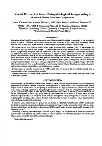
directions after removing from the lists the normals that already belong to a detected dominant direction, since a line corresponds to only one single direction. Figures 4 and 5 show some results obtained by this method from diverse video sequences. One may note that a line may belong to a wrong set of parallel lines if it accidentally goes through the intersecting spot of those parallel lines. After extracting dominant directions and their associated parallel lines, we aim to detect whether some directions are orthogonal. It has been proved in [7] that the direction of the antipodal points in the sphere correspond to the direction of the parallel lines associated in these antipodal points in world space (cf. Fig 3). Note that the same property actually holds for perspective cameras also. Thanks to this theorem, if two sets of lines are orthogonal in world space, then their antipodal points will also be orthogonal and thus it is possible to determine automatically whether two sets of lines are orthogonal. The experiments associated to the figure 4 have shown that the three most dominant directions are orthogonal mutually. Therefore, we are able to detect parallel and orthogonal lines in catadioptric images.
Figure 5. Top: detection of the three most dominant directions and their associated parallel lines in an image pair. Each conic represents a detected line and its color corresponds to the set of parallel lines it belongs to. Bottom: display of the points associated to the detected lines. Each color is chosen randomly and corresponds to a detected line.
5. Detection of rectangles in catadioptric images: general case As previously explained, we suggest working in the sphere rather than the catadioptric image and we have shown that it is possible to automatically detect parallel and orthogonal lines belonging to dominant directions. In order to build a list of candidate rectangles, we make combinations composed of four lines that are parallel and orthogonal mutually. Among these combinations, we simply select those verifying a “closed contour” constraint. This constraint is composed of two obvious rules: first, the two endpoints of a line must be associated with two different orthogonal lines (otherwise T-structure) and secondly, the intersection of two perpendicular lines must be near one endpoint of each of these two lines. Concretely, for a pair of great circles whose normals ni and nj are orthogonal (i.e. their associated lines are perpendicular), we compute their intersection by normalized cross product
u = ± ( ni × n j ) / ni × n j . Two antipodal points on the
Figure 4 : experimental results of the three most dominant directions extraction (row 1 to 3) for two different images (left and right column) of the sequence.
sphere are obtained and we calculate the geodesic distance between the antipodal points and the lines endpoints. We define that two orthogonal great circles intersect correctly if an endpoint of each line is near a same antipodal point. Formally, it can be written as follow: min d (u, C1, j ) ≤ Thresh and min d (u, C2, j ) ≤ Thresh j =1,2
j =1,2
or min d (−u , C1, j ) ≤ Thresh ad min d (−u , C2, j ) ≤ Thresh j =1,2
j =1,2
where Ci,j represents the jth endpoint of the ith great circle in the sphere and u one of the two antipodal points. Finally, we have tested our algorithm on real catadioptric images. As depicted by figures 7 and 8, experiments have permitted to verify the validity of the proposed method.
Figure 7: Examples of intermediate steps in the rectangle detection process and the role played by the closed contour constraint. Left: combination of two sets of parallel lines (respectively displayed in red and color with their associated points in green) that are orthogonal mutually. Right: combination of four lines that do not verify the closed contour constraint.
Figure 8 : Examples of rectangles detected by our proposed algorithm for the 1st and 60th frame of the image sequence.
6. Detection of rectangles in catadioptric images: particular case In this section, we aim to show how the knowledge of the plane normal can be used to facilitate the extraction of parallelism and orthogonality and thus the detection of rectangles. In world space, let d1 and d2 be two lines whose unit vectors are u1 and u2 and that belong to a plane P characterized by its normal vector n. These two lines are projected on the sphere as great circles whose normals are n1 and n2. A simple relation holds between the unit vector of a line, its associated plane and the great circle plane:
Figure 6: Detection of the three most dominant directions and their associated lines in two other videos (row 1-2 and 3-4) to depict the robustness of the method.
u1 = n1 × n for d1 and u2 = n2 × n for d2. Generally, since only the great circles normals are known (i.e. n1 and n2), it is not possible to retrieve the unit vector of lines. Actually, in some applications, the plane normal is known
(e.g. ground plane normal for a car moving on a flat ground) or can be estimated (by laser or 3D reconstruction for instance). Therefore, the vectors of each line can be calculated by cross product and it becomes easy to extract parallel and orthogonal lines automatically (cf Fig 9-10). Among combinations of parallel and orthogonal lines, we simply select those verifying the “closed contour” constraint. In order to test our algorithm, we have first used POV-Ray program for synthesizing catadioptric views where the plane normal is known. The synthesized views have been made such that they correspond to various situations: rectangles with different rotations, translations and scales. Figure 11 depicts the obtained results. Finally, we have also applied our method to real images. In order to estimate the normal of a certain plane, we have manually selected two sets of parallel lines of this plane and compute their cross product. Another solution could be to estimate the homography H between two planes in a pair of images and get the plane normal from the decomposition of H. We have also manually defined a region in which to search the rectangles. The results are depicted by Figure 12 and have shown the validity of our approach.
corresponding to the intersection of parallel lines is the same direction that the parallel lines in world space. Therefore, parallel and perpendicular lines can be extracted in catadioptric images. Finally, we have shown that the knowledge of the plane normal facilitates the detection of parallelism and orthogonality. Experiments on synthesized and real images have validated our method. Future work will concern extraction of planes in image sequences based on detected rectangles.
Figure 10 : Example of automatic extraction of parallel lines in synthesized catadioptric images with the knowledge of the plane normal (only four directions out of five are displayed).
Figure 9. Left: synthesized catadioptric image obtained by POV-Ray in which the objects belong to a same plane whose normal is known: (0,0,1). Compared to the cyan rectangle, the red one is scaled and the magenta one has been rotated around its normal. The green object is a parallelogram. Right: line extraction by our algorithm where red conics correspond to the detected catadioptric lines and the green parts to the associated pixels.
7. Conclusion Whereas catadioptric sensors are more and more used in robotic, several problems inherent to catadioptric vision have not been studied yet. We have focused on the development of a method for automatic detection of rectangles in catadioptric images. To the best of our knowledge, this is the first paper to face this problem. We have shown that working in the sphere space provides some important properties. First, a catadioptric line corresponds to a great circle in the sphere, which facilitates the extraction of lines in the image. Second, a set of parallel lines intersect in two antipodal points. Third and last advantage is that the direction of the antipodal points
Figure 11 : results of the proposed algorithm. The 3 rectangles have been correctly detected. Note that the parallelogram has been automatically rejected because its lines do not verify the orthogonality constraint.
Figure 12. Top: definition of the search region. Bottom: examples of rectangles extracted by our method based on the plane normal knowledge in the specified search region.
References [1] S. Baker, S. Nayar: a Theory of Catadioptric Image Formation, Proceedings of International Conference on Computer Vision (ICCV), p. 35-42, 1998. [2] W. Barret and K. Petersen: Houghing the Hough: Peak Collection for Detection of Corners, Junctions and Line Intersections, Proceedings of the Conference on Computer Vision and Pattern Recognition (CVPR), Vol.2, 2001. [3] J.P. Barreto, General Central Projection Systems: Modelling, Calibration and Visual Servoing, PhD Thesis, University of Coimbra, 2003. [4] J.P. Barreto, H; Araujo: Fitting conics to paracatadioptric projections of lines, Computer Vision and Image Understanding 101(3), 151–165, 2006. [5] J.C. Bazin, C. Demonceaux, P. Vasseur, Fast Central Catadioptric Line Extraction, Iberian Pattern Recognition and Image Analysis (IbPRIA), 2007. [6] Massimo Bertozzi and Alberto Broggi, GOLD: a Parallel Real-Time Stereo Vision System for Generic Obstacle and Lane Detection, IEEE Transactions on Image Processing, 7(1):62-81, 1998. [7] C. Demonceaux and P. Vasseur, UAV Attitude Computation by Omnidirectional Vision in Urban Environment, International Conference on Robotics and Automation (ICRA), 2007 [8] A.W. Fitzgibbon, R.B. Fisher: A buyer’s guide to conic fitting. In BMVC, 1995. [9] A. French, S. Mills and T. Pridmore: Condensation Tracking Through Hough Space, Proceedings of the 17th International Conference on Pattern Recognition (ICPR), pp 195-198, 2004. [10] C. Geyer and K. Daniilidis, Catadioptric camera calibration, Proceedings of International Conference on Computer Vision (ICCV), Vol. 1, pp. 398-404, 1999. [11] C. Geyer and K. Daniilidis, Catadioptric projective geometry, International Journal of Computer Vision (IJCV), 45(3), pp223-243, 2001.
[12] R. Hartley and A. Zisserman. Multiple View Geometry in Computer Vision, Cambridge University Press, second edition, 2004. [13] A. Jennings, J.J. McKeown, Matrix Computation, 2nd edition, John Wiley & Sons, New York, 1992. [14] C.R. Jung, R. Schramm: Rectangle Detection Based on a Windowed Hough Transform, Proceedings of the XVII Brazilian Symposium on Computer Graphics and Image Processing (SIBGRAPI), pp113-120, 2004. [15] C. Mei, E. Malis: Fast central catadioptric line extraction, estimation, tracking and structure from motion. In IROS, 2006. [16] B. Vandeportaele, M. Cattoen, P. Marthon: A fast detector of line images acquired by an uncalibrated paracatadioptric camera, In International Conference on Pattern Recognition ICPR, (3), pp. 1042–1045, IEEE Computer Society Press, Los Alamitos, 2006. [17] P. Vasseur, E.M. Mouaddib: Central catadioptric line detection. In BMVC, 2004. [18] X. Ying, Z. Hu: Catadioptric line features detection using hough transform. In International Conference on Pattern Recognition ICPR (4), pp. 839–842. IEEE Computer Society Press, Los Alamitos 2004. [19] W. Zhang, J. Kosecka: Extraction, Matching and Pose Recovery Based on Dominant Rectangular Structures, IEEE Workshop on Higher-Level Knowledge in 3D Modeling and Motion Analysis, 2003 [20] Z. Zhang: Parameter estimation techniques: a tutorial with application to conic fitting, technical report INRIA Sofia Antipolis, 1995.