the recently proposed VCTM. 1. Introduction. As the clock speed race turns into the core count race in the current microprocessor trend, providing efficient com-.
Recursive Partitioning Multicast: A Bandwidth-Efficient Routing for Networks-On-Chip Lei Wang, Yuho Jin, Hyungjun Kim and Eun Jung Kim Department of Computer Science and Engineering Texas A&M University College Station, TX, 77843 USA {wanglei, yuho, hkim, ejkim}@cse.tamu.edu
Abstract Chip Multi-processor (CMP) architectures have become mainstream for designing processors. With a large number of cores, Networks-on-Chip (NOCs) provide a scalable communication method for CMP architectures. NOCs must be carefully designed to meet constraints of power consumption and area, and provide ultra low latencies. Existing NOCs mostly use Dimension Order Routing (DOR) to determine the route taken by a packet in unicast traffic. However, with the development of diverse applications in CMPs, one-to-many (multicast) and one-to-all (broadcast) traffic are becoming more common. Current unicast routing cannot support multicast and broadcast traffic efficiently. In this paper, we propose Recursive Partitioning Multicast (RPM) routing and a detailed multicast wormhole router design for NOCs. RPM allows routers to select intermediate replication nodes based on the global distribution of destination nodes. This provides more path diversities, thus achieves more bandwidth-efficiency and finally improves the performance of the whole network. Our simulation results using a detailed cycle-accurate simulator show that compared with the most recent multicast scheme, RPM saves 25% of crossbar and link power, and 33% of link utilization with 50% network performance improvement. Also RPM is more scalable to large networks than the recently proposed VCTM.
1. Introduction As the clock speed race turns into the core count race in the current microprocessor trend, providing efficient communication in a single die is becoming a critical factor for high performance CMPs [15]. Traditional shared buses that can connect only a handful number of components do not satisfy the need for a chip architecture containing tens to hundreds of processors. Moreover, the shrinking tech-
nology exacerbating the imbalance between transistors and wires in terms of delay and power has embarked on a fervent search for efficient communication designs [9]. In this regime, Networks-On-Chip (NOCs) are a promising architecture that orchestrates chip-wide communications towards future many-core processors. NOCs are implemented as a switched network connecting cores in a flexible and scalable manner, which achieves higher performance, higher throughput, and lower power consumption than a bus-based interconnect. Recent innovative tile-based chip multiprocessors such as Intel Teraflop 80-core [10] and Tilera 64-core [20] gain high interconnect bandwidth through 2D mesh topologies. Mesh networks match well a planar silicon geometry and provides better scalability and higher bandwidth than 1Dbased bus or ring networks. However, the implementation cost of NOCs is constrained within tight chip power and area envelopes. In fact, NOCs power consumption is significant enough to occupy 28% of the tile power in Teraflop [10] and 36% of the total chip power in 16-tile RAW chip [18]. In the (5×5) mesh operand network of TRIPS, the router takes up to 10% of the tile area mostly due to FIFO buffers [8]. Therefore, any existing high-cost feature or new functionality needs to be carefully examined if it unduly increases the design cost. Looking to the future, supporting one-to-many communication such as broadcast and multicast in NOCs will provide many potentials in diverse application domains and programming models. In cache-coherent shared memory systems with a large number of cores, partitioned cache banks, and multiple memory controllers, hardware-based multicast is critical in maximizing performance. In fact, cache coherence protocols heavily rely on multicast or broadcast communication characteristics to maintain ordering amongst requests [14] or to invalidate shared data spread on different caches using directory. Motivated by the importance of multicast and broadcast support, recent work pro-
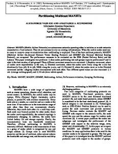
posed these functions in the design of the routers [11, 17]. The key problem is to decide when and where to replicate multicast packets. Poor replication decisions can significantly degrade network performance and increase the power consumption of links because multicast or broadcast communications easily exhaust the network bandwidth. Figure 1 shows two different routing examples in a (4×4) mesh network for the same traffic pattern where the source is 9 and its four destinations are 0, 1, 2, and 3. In Example 1, packet replication occurs in routers 9 and 10, while in Example 2, packet replication occurs in routers 1 and 2. Note that the total number of replication operations is the same (three) in both examples. However, Example 2 performs packet delivery with only 5 links while Example 1 does with 11 links. As a result, Example 1 consumes 2.2 times link bandwidth of the network than Example 2. This increased bandwidth usage may cause contention in links and router ports, hence, increasing the latency. Furthermore, Example 1 dissipates more power due to more operations (buffer read/write, crossbar traversal, and link traversal) than Example 2. Examples in Figure 1 clearly show the need for intelligent routing algorithms for multicasting. Motivated by this problem, we propose a novel Source
Destination
0
1
2
3
0
1
2
3
4
5
6
7
4
5
6
7
8
9
10
11
8
9
10
11
12
13
14
15
12
13
14
15
(a) Example 1
(b) Example 2
Figure 1. Different Bandwidth Usage in Multicasting for Four Destinations: Example 1 requires 11 link traversals, 12 buffer writes, 15 buffer reads, and 15 crossbar traversals, while Example 2 requires 5 link traversals, 6 buffer writes, 10 buffer reads, and 10 crossbar traversals. routing algorithm called Recursive Partitioning Multicast (RPM). The basic idea is that a routing path is computed based on all the destination positions in a network, and the network is recursively partitioned according to the position of the current router. The current node computes the output ports using a new partition and its destination list of the packet, and makes one packet replica for each output port. The replicated packet has an updated destination list, which
excludes destinations in different delivery directions. This is required to prevent redundant packet delivery. Because each intermediate router uses RPM to make a routing decision, the whole packet traversal path is optimized. In this way, RPM can reduce the whole network link utilization. As a result RPM improves network bandwidthefficiency and decreases power consumption. Our main contributions are summarized as follows: • We propose a new routing algorithm, Recursive Partitioning Multicast (RPM), to support multicast traffic in NOCs. • We explore the details of the multicast wormhole router architecture, especially the virtual channel arbiter and switch arbiter designs. • We evaluate different multicast schemes by varying the traffic pattern in unicast traffic, multicast traffic portion, and the average number of destinations. Additionally, we show a good scalability of our scheme as the network size increases. • Detailed simulation results show that RPM saves 25% of crossbar and link power and 33% of link utilization with 50% latency improvement compared with the recently proposed VCTM. The rest of this paper is organized as follows. We briefly analyze the recent multicast work in Section 2. We propose the multicast router design in Section 3. RPM routing is discussed in Section 4. In Section 5, we describe evaluation methodology and summarize the simulation results. Finally, we draw conclusions in Section 6.
2. Related Work Multicast (one to many) and broadcast (one to all) refer to the traffic pattern in which the same message is sent from one source node to a set of destination nodes. A growing number of parallel applications show the necessity to provide multicast services. The main problem of multicast is to determine which path should be used to deliver a message from one source node to multiple destination nodes. This path selection process is called multicast routing. There are several multicast routing schemes. Multiple unicast is the simplest one. In multiple unicast, routers do not need to add any extra component and just treat multicast traffic as unicast traffic. Tree-based multicast routing [13] is to deliver the message along a common path as far as possible, then replicate the message and forward the copy on a different channel bound for a unique set of destination nodes. The path followed by each copy will further branch in the same manner until the message reaches every destination node.
Multicast communication has been studied in distributed systems [7], local-area networks [1] and multicomputer networks [12]. However, supporting multicast in NOCs has different requirements, because current NOCs have power and area constraints with high performance requirement. Most recent work on multicast routing in NOCs is Virtual Circuit Tree Multicasting [11] and bLBDR [17]. The work in [11] proposes an efficient multicast and broadcast mechanism. However, the main disadvantages of VCTM are threefold. First, VCTM needs extra storage to maintain the tree information for multicast, which needs more chip area. Second, before sending multicast packets, VCTM needs to send a setup packet to build a tree, introducing multicasting latency. Third, even with the same set of nodes, if the multicast source node changes, VCTM should build another tree. This makes VCTM not scalable to large networks. bLBDR [17] enables the concept of virtualization at the NOC level and isolates the traffic into different domains. However, multicasting in bLBDR is based on broadcasting in a small domain. The problem of this scheme is that it is hard to provide multicasting if the destination nodes are spread in different parts of the network, because it is hard to define a domain to include all the destination nodes.
3. Multicast Router Design Our Recursive Partitioning Multicast is built on the stateof-the-art wormhole-switched router. In this section, we briefly present a general router architecture and propose our RPM router architecture.
3.1. General Router Architecture Figure 2 shows a virtual channel (VC) router architecture used in NOCs [6]. The main building blocks are input buffer, route computation logic, VC allocator, switch allocator, and crossbar. To achieve high performance, the router processes packets with four pipeline stages, which are routing computation (RC), VC allocation (VA), switch allocation (SA), and switch traversal (ST). First, the RC stage directs a packet to a proper output port of the router by looking up a destination address. Next, the VA stage allocates one available VC of the downstream router determined by RC. The SA stage arbitrates input and output ports of the crossbar, and then successfully granted flits traverse the crossbar in the ST stage. Due to the stringent area budget of a chip, routers use flit level buffering for wormhole-switching as opposed to packet level buffering. Additionally, buffer is managed with credit-based flow control, where downstream routers provide back-pressure to upstream routers to prevent buffer overflow. Because the router latency affects the packet delivery latency significantly, recent router designs use techniques such as lookahead routing and speculative switch alloca-
Route Computation
Input 0
VC Allocator Switch Allocator
VC 1
Output 0
VC 2
.
.
VC n Input buffers
.
.
.
. VC 1
Input 4
Output 4
VC 2 VC n Input buffers
Crossbar switch
Figure 2. Baseline Router Architecture tion [16], to reduce the number of pipeline stages. Lookahead routing removes the RC stage from the pipeline by making a routing decision one hop ahead of the current router. Speculative switch allocation enables the VA stage to be performed with the SA stage simultaneously. A separate switch allocator finds available input and output ports of the crossbar after the normal switch allocator reserves them. In this work, our basic wormhole router supports both techniques, hence having only two stages.
3.2. RPM Router Architecture In multicast traffic, a packet that has multiple destinations needs to be replicated to several copies in intermediate routers. To support a multicast function, routers need a replication component with modification of existing VC and switch allocators used in unicast routers. In wormhole switching, a router sends out a flit to the next router before receiving the rest of the flits in the same packet. To avoid the storage overhead for replica management, replications take place at the ST stage, and the basic unit is a flit rather than a packet. When the switch allocation for one flit at the head of selected VC succeeds, the flit is replicated and sent out to the downstream router. In this way, current router does not need to hold replicated flits. Actually, the replication component in our multicast wormhole router is only a control logic, thus, it will not consume much area. 3.2.1. Replication Scheme Replication schemes are instrumental to improve the performance of multicast router. Two replication schemes are proposed in literature: synchronous and asynchronous replication [4]. Synchronous replication requires multicast packets to proceed in a lock-step. At a fork, a flit in those packets can proceed only when all of its target output ports are avail-
able. Any branch replica which is blocked can block other branch replicas of the same multicast packet. In terms of this nature, synchronous replication is susceptible to deadlock. In other words, if two multicast packets holding an output port request output ports reserved by each other, neither of them can advance. They will block each other forever. Thus, synchronous replication needs additional feedback architecture [4] to confirm that flits are processed in a lock-step. However, in asynchronous replication, branch replicas will not block each other, since each of them proceeds independently. Asynchronous replication is preferred for a practical implementation due to the following reasons. First, it does not need additional feedback architecture. Second, each replica is independent of others which reduces individual packet latency. Third, there is no potential deadlock inside the router. For the above reasons, we select asynchronous replication scheme in this paper. 3.2.2. Virtual Channel and Switch Allocator Design The basic function of VC and switch allocator is to do arbitration among different requesters, which request the same resource, and map those requests to free resources. In VC allocation, the unit of operation is a packet. We need to maintain the status of each VC to keep track of how far the packet has proceeded in a router. Right after the tail flit is sent to the SA stage, the VC status information is to be flushed and this VC is available for other packets. Unlike unicast, maintaining the status information for a multicast packet is more complicated. One multicast packet needs to reserve multiple output ports. Some ports may be free while others may not. As we are using asynchronous scheme, if one replica gets a free VC from its selected output port, that replica can go to the SA stage while the failed replicas toward other branches keep requesting in the following cycles until they pass that stage. Finally, the router will flush the VC status when the last replica’s tail flit departs the input buffer. For switch allocation, we choose two-stage arbiter. The first stage is doing arbitration among different VCs which belong to the same physical input port. This stage is the same as unicast router. The second stage is doing arbitration among different winning VCs from the first stage which go for the same output port. Differences exist between a unicast router and a multicast router. In unicast, one input VC has only one candidate output port, so its request goes for only one second-stage arbiter. However in multicast, two or more output ports can be requested by the same winning VC, and its requests should go to several different secondstage arbiter. Even more, some requests may succeed and some may fail. In this scenario, we continuously follow the asynchronous scheme. The successful request can make a
flit copy and transmit it to the downstream router. The failed ones are waiting for the next arbitration chance. In our router design, we use the round-robin arbiter in both VC and switch allocation. We do not assign any priority between multicast packets and unicast packets. We believe that if we use more intelligent priority arbitration in this part, the performance of the whole network can be improved further. This work is left for the future.
3.2.3. Destination List Management The header of a packet carries the addresses of its destination nodes. Several approaches have been made to find out an efficient way to put multiple destination addresses into the header such as all-destination encoding, bit string encoding, and multiple-region broadcast encoding [3]. The all-destination scheme puts each destination node identifier into the header. This approach is good when the number of destinations is small but it introduces a significant overhead when the number becomes large. Bit string encoding uses a bit-vector where each bit represents one destination node. This scheme performs well when the number of destinations is large. In the multiple-region broadcast encoding scheme, the header carries ranges of destination addresses: the beginning and ending addresses of regions. The message is, then, sent to all addresses in those ranges. The main disadvantage of this scheme is that it is expensive to decode addresses. Further efforts have been made to minimize the header length and the header processing time. Bit string encoding is used in our work. Figure 3 depicts an example of a multicast and its corresponding packet header. The packet header contains a bit string which is of length of the number of nodes in the network. A bit in this string corresponds to a node and setting a bit means that the node is one of the destinations. Since the destination information is carried in the packet header, there is no need to maintain tables in the intermediate routers for routing computation, thus we can save chip area and time to setup those tables. As the network size grows, the number of bits increases only linearly. Using the bit string encoding, the intermediate router has to generate output bit string (s) to avoid redundant replication. When a packet reaches a destination, the bit corresponding to that destination node must be reset. Otherwise, the next router which receives this packet will send it back to the previous one. At a fork, the destination list must be exclusively divided into subsets such that packets forwarded to different directions should not meet at the same node in the future. This destination list management is done when packets are replicated at the ST stage. Detailed discussion with examples can be found in the following section.
7 2
1
N 5
3 4
Source node
0 6
7 5
W
E
6
Eight Parts
Three Parts (5, 6, 7)
S
3 0 4
1
7
Figure 3. Packet Header Example
4. Recursive Partitioning Multicast (RPM) In this section, we propose the RPM routing algorithm, achieving deadlock freedom as well as bandwidth efficiency.
4.1. RPM Routing Our RPM routing algorithm is built on the multicast router hardware explained in Section 3. Unlike VCTM, RPM do not maintain any lookup table for multicast in each router. RPM directly sends out multicast packets without sending a unicast+setup packet to each destination first. In other words, RPM does not need to build a tree structure in each intermediate router before sending the real multicast data packet. However, in each multicast packet header, we need one field to indicate the destination nodes’ positions. In RPM, the routing decision is made based on the current network partitioning. A source node divides the whole network into at most eight parts according to its position. Then destination nodes in a multicast packet belong to one of these parts. In general case, if the source node is in the center of the network, all the eight parts have at least one node. However, if the source node is located in the corner of the network, some parts may be empty. Taking a (4×4) mesh network as an example, partitioning is defined as Figure 4. Since the source node, which is in the center of the network, always has at least one node in each part, we normally choose the center node as our multicast source node in the following discussion. Normally, at the RC stage, the input of routing computation component is a destination list from the packet header, and the output is an output port identifier. However, when the packet is a multicast packet, the output port identifier may not be unique. One packet can go for different output ports simultaneously. Some destination nodes can be reached through more than one directions. For example, one destination node is in the northeast direction of the source node. Then north and east directions are two routing deci-
Three Parts (0, 1, 7)
5
2
1
3 Three Parts (3, 4, 5)
Three Parts (1, 2, 3)
Figure 4. Network Partitioning Based on Source Node Positions
sion candidates for that node. Only one direction we can choose for that destination node, since we want to achieve bandwidth efficiency in our multicast routing. The key point is how we can minimize packet replication times, in other words, maximizing the reusability of each replica. To avoid redundant replication, we define replication priority rules for each direction. Basic priority rules (Figure 5(a)) • North direction has a higher priority than East to reach destination nodes in Part 0 (Northeast Part). • West direction has a higher priority than North to reach destination nodes in Part 2 (Northwest Part). • South direction has a higher priority than West to reach destination nodes in Part 4 (Southwest Part). • East direction has a higher priority than South to reach destination nodes in Part 6 (Southeast Part). However, only with the above basic rules, in some cases, we still cannot maximize the reusability of some replicas. To make the replication point selection more bandwidthefficient, besides the above basic rules, we propose additional rules. Optimized priority rules • If there are destination nodes in both Part 0 (Northeast Part) and 2 (Northwest Part), North direction replication will be used for both of them. The same rule is applied to South direction, as in Figure 5(b). • Part 1 and 2 have destination nodes, but Part 3 does not have any. In this case North direction replication, not West, will be used for destination nodes in Part 2. The same rule is applied to South direction, as in Figures 5(c) and (d).
Source
a0 a1 a2
Destination bit-encoded destinations
2
1
0
2
7
3
6
4
1
0
an-1
Part 0 Part 1 Part 2 Part 3 . partitioning Part 4 logic . Part 5 . Part 6 Part 7
a0 ~ an-1: node address Part 0 ~ Part 7: partition
N E
3 4
W
7
N
S
5
6
5
(b)
(a)
E
2
1
0
2
1
0 S
3 4
5
(c)
7
3
6
4
7 5
6
(d)
Figure 5. Basic Routing Priority
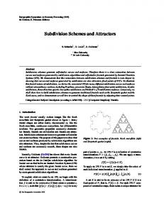
Besides the above replication priority for each direction, when replicated packets are sent out at the ST stage, current router will modify the original packet header, deleting useless destinations from the old destination list. After this the packet replica for each direction only has a subset of destination nodes in its packet header, which facilitates that this replica only sent to the subset destination nodes. We can build the original destination list from all the subset destination lists, and there are no redundant nodes in each subset list. The pseudo-code for the operation of the routing computation is in Table 1 and its hardware implementation is shown in Figure 6. The RPM logic consists of two steps. At the first step, the partitioning logic finds out which parts the packet has to be sent to. It takes the destination information (bit-encoded destinations) from the header as input and produces the output (Part 0, Part 1, ... , and Part 7) according to the current location. The second step is the core of the routing logic. With the help of the intermediate result from the partitioning logic, the decision on output ports (N, E, S, or W) is made in this step. To make it more clear, we use the example in Figure 7 to walk through the process of sending a multicast packet to all destinations. When the network interface in Node 9 initiates one multicast packet, the routing computation component decodes the destination list in the packet header (current destination nodes are 0, 2, 3, 13, and 15). At step 1, according to Node 9’s position, the destination nodes are in four parts (0, 2, 5, and 6). Based on the routing priority rules, Node 9 only needs to make one copy of the packet, and sends original packet to North and the new copy to South. In North direction, the destination list only contains Nodes 0, 2, and 3. In South direction, the destination list only has
W
Figure 6. Hardware Implementation of Routing Logic if IN(dest,7) OR (IN(dest,6) AND !IN(dest,5) AND !IN(dest,4) then ADD(EAST) if IN(dest,1) OR (IN(dest,0) AND (!IN(dest,7) OR !IN(dest,4) AND IN(dest,6))) OR (IN(dest,0) AND IN(dest, 2)) then ADD(NORTH) if IN(dest,3) OR (IN(dest,2) AND !IN(dest,1) AND !IN(dest,0)) then ADD(WEST) if IN(dest,5) OR (IN(dest,4) AND (!IN(dest,3) OR !IN(dest,0) AND IN(dest,4))) OR (IN(dest,4) AND IN(dest,6)) then Add(SOUTH) IN(dest, n): at least one destination node is in part n. ADD(direction): add direction as candidate.
Table 1. Pseudo-Code for Routing Computation
Nodes 13 and 15. At step 2, one replica arrives at Node 5. Now the new partitioning is based on Node 5’s position. Node 5 can only see three destination nodes (0, 2, and 3) and they are in Part 0 and 2. Node 5 does not need to do any replication and just forward the same packet to Node 1 in its North direction. Another replica arrives at Node 13. Unlike Node 5, Node 13 should make a copy. One goes to an ejection port since Node 13 itself is a destination node and the other is forwarded to Node 14 with only Node 15 in its destination list. At step 3, Node 1 finds that Node 0 lies in Part 3 and that Nodes 2 and 3 lie in Part 7. So Node 1 makes one new copy. The original packet goes to West direction and the new copy goes to East. This recursive partitioning continues at step 4 and 5. Finally, all the destination nodes receive the packet.
Step 1
Step 3
Step 2
Current node Destination node
Step 4
Step 5
0
1
2
3
0
1
2
3
0
1
2
3
0
1
2
3
4
5
6
7
4
5
6
7
4
5
6
7
4
5
6
7
8
9
10
11
8
9
10
11
8
9
10
11
8
9
10
11
12
13
14
15
12
13
14
15
12
13
14
15
12
13
14
15
0
1
2
3
0
1
2
3
0
1
2
3
0
1
2
3
4
5
6
7
4
5
6
7
4
5
6
7
4
5
6
7
8
9
10
11
8
9
10
11
8
9
10
11
8
9
10
11
12
13
14
15
12
13
14
15
12
13
14
15
12
13
14
15
Ejection node 0
1
2
3
4
5
6
7
8
9 s
10
11
12
13
14
15
Figure 7. Multicast Packet Traveling Example
4.2. Deadlock Avoidance Deadlock freedom is an important feature for every routing algorithm. The routing algorithm explained so far is likely to produce deadlock since no turn restriction is defined. Without any turn restriction, flows in the same network may cause a cyclic dependency, which freezes movement of all packets in a cycle. To guarantee deadlock freedom, a turn restriction must be given. Packets in different paths do not generate any cycle in the network. Most of deadlock avoidance techniques are designed to remove cyclic dependency as in [5]. Virtual network (VN) is introduced to make writing a deadlock-free algorithm easy by separating a physical network into multiple virtual networks; each of those networks does not produce cycles by itself. It has been extensively explored in previous interconnection research in [2]. Taking a 2D mesh topology as an example, two VNs (VN0 and VN1) lie in the same physical network and are used as a pair. VN0 does not allow packets to turn from a current location to North whereas VN1 does not allow packets to turn to South. Using deadlock-free VNs makes no cycle in a network either clockwise or counterclockwise since some turns to form a cycle are prohibited. Once the whole network is divided into two VNs, packets also must be distinguished by which VN they should follow. One bit in the packet header is used to indicate VN identifier as shown in Figure 3. A source router where the multicast is initiated defines this bit at the RC stage. If destinations lie in the upside of the source router, the packet goes through VN0, whereas if destinations are in the downside, the packet takes VN1. Note that if destinations lie in both sides, the source node makes two copies, one for up
and the other for down. Intermediate routers never change the VN bit and only forward the packet to the same VN in which the packet has traveled.
5. Experimental Evaluation We evaluated RPM with different synthetic multicast workloads, comparing it with VCTM. We also examined RPM’s sensitivity to a variety of network parameters.
5.1. Methodology We use a cycle-accurate network simulator that models all router pipeline delays and wire latencies. We use Orion [19] to estimate dynamic and static power consumption for buffer, crossbar, arbiter, and link with 50% switching activity and 1V supply voltage in 65nm technology. We assume a clock frequency of 4GHz for the router and link. For a (8×8) mesh network, the area of one tile is 2mm x 2mm, resulting in a chip size as 256mm2 . We model a link as 128 parallel wires, which takes advantage of abundant metal resources provided by future multi-layer interconnect. We consider network sizes of 36, 64, 100, and 256 terminals. We use 2-stage router and synthetic workloads for performance evaluation. On top of Uniform Random (UR), Bit Complement (BC) and Transpose (TP) unicast packets, our synthetic workloads have multicast packets. For multicast packets, the destination numbers and positions are uniformly distributed, while unicast packet’s destination positions are determined by three patterns (UR, BC, and TP). We also control the percentage of multicast packets in whole packets. Table 2 summarizes the simulated configurations, along with the variations used in the sensitivity study.
Characteristic Topology Routing Virtual Channels/Port Virtual Channel Depth Packet Length(flits) Unicast Traffic Pattern Multicast Packet Portion Multicast Destination Number Simulation Warmup Cycles Total Simulation Cycles
Baseline 8×8 Mesh RPM and VCTM 4 4 4 Uniform Random 10% 0-16 (uniformly distributed) 10,000 20,000
Variations 6×6 Mesh, 10×10 Mesh, 16×16 Mesh – – – – Bit Complement, Transpose 5%, 20%, 40%, 80% 0-(4, 8, 32) (uniformly distributed) – –
Table 2. Network Configuration and Variations
Figure 9 shows the power consumption of the two schemes. We assume 80% entries of virtual circuit table reusable for VCTM. Although we ignore the power consumption of the virtual circuit table for VCTM, we observe that RPM is more power efficient than VCTM. Before network is saturated, for example load 0.1, RPM saves almost 60% power consumption compared with VCTM. Because we use the same network configurations in RPM and
Static Power
15 10
a
0
RPM VCTM RPM VCTM RPM VCTM RPM VCTM RPM VCTM RPM VCTM RPM VCTM RPM VCTM RPM VCTM RPM VCTM RPM VCTM RPM VCTM RPM VCTM RPM VCTM RPM VCTM RPM VCTM RPM VCTM RPM VCTM
5
0.01 0.02 0.03 0.04 0.05 0.06 0.07 0.08 0.09 0.1 0.15 0.2 0.25 0.3 0.35 0.4 0.45 0.5
Injection Rate(flits/cycle/core)
Figure 9. Power Consumption (Dynamic and Static) in an (8×8) Mesh Network. (10% multicast traffic, average 8 destinations)
Buffer
VC Arbiter
SW Arbiter
Xbar
Link
12 10 8 6 4 2 0 RPM VCTM RPM VCTM RPM VCTM RPM VCTM RPM VCTM RPM VCTM RPM VCTM RPM VCTM RPM VCTM RPM VCTM RPM VCTM RPM VCTM RPM VCTM RPM VCTM RPM VCTM RPM VCTM RPM VCTM RPM VCTM
5.3. Power
Dynamic Power 20 Total Power(W)
Figure 8 summarizes the simulation results of an (8×8) network with the three synthetic traffic patterns. Mul unicast means sending multicast packet as multiple unicast packet, one by one. VCTM (80%) means 80% of entries in the virtual circuit table can be reused by different multicast packets. RPM has the lowest average packet latency, 50% of that of VCTM at low loads and almost 25% at high loads. When we look at the network saturation points, RPM saturates at higher loads, 20% higher than VCTM, which means RPM can provide high throughput. The results are consistent with our expectations. The performance improvement comes from two main reasons: First, since a multicast packet in RPM carries a destination list in the packet header, we do not need setup packets to each destination node to construct a tree. This reduces the actual number of injected packets in the network and also gets rid of the setup delay. Second, the routing paths generated by RPM do not strictly follow a dimension order. According to our description in Section 4, RPM selects the routing path based on global distribution of destination nodes. This feature can provide more diverse paths than VCTM, which means links in the whole network can be fairly used with less contention. Also we observe that when the rate of virtual circuit table reusability decreases (more than 30% degradation), the performance of VCTM decreases much. This indicates the performance of VCTM is sensitive to the reusability of virtual circuit table. To keep high reusability in a large network, VCTM needs a big table which consumes larg chip area.
VCTM, the static power consumption is the same but dynamic power consumption is different. Figure 10 summarizes the dynamic power consumption of each component in a router. Crossbar power and link power are dominant. Because RPM uses less crossbar and link resources than VCTM, it saves 25% crossbar and link power. The same conclusion can be drawn from Figure 11, which shows the average link utilization of RPM and VCTM. RPM saves almost 33% of link utilization compared with VCTM (80%).
Dynamic Power(W)
5.2. Performance
0.010.020.030.040.050.060.070.080.09 0.1 0.15 0.2 0.25 0.3 0.35 0.4 0.45 0.5
Injection Rate(flits/cycle/core)
Figure 10. Dynamic Power Consumption in an (8×8) Mesh Network. (10% multicast traffic, average 8 destinations)
VCTM(20%)
0.05
0.07
0.09
0.15
RPM
Mul unicast
RPM
Mul unicast
VCTM (40%)
VCTM (80%)
VCTM (40%)
VCTM (80%)
0.05
120 100 80 60 40 20 0 0.01
0.05
120 100 80 60 40 20 0 0.01
VCTM (20%)
Latency(cycle)
Mul unicast VCTM(80%)
Latency(cycle)
Latency(cycle)
RPM VCTM(40%) 120 100 80 60 40 20 0 0.01 0.03
0.03
Injection rate(flits/cycle/core)
0.07
0.09
0.15
0.03
Injection rate(flits/cycle/core)
(a) Uniform Random
0.07
VCTM (20%)
0.09
0.15
Injection rate(flits/cycle/core)
(b) Bit Complement
(c) Transpose
Figure 8. Packet Latency with Three Synthetic Traffic Patterns in an (8×8) Mesh Network. (10% multicast traffic, average 8 destinations)
VCTM(20%)
VCTM(40%)
RPM
VCTM(80%)
Latency(cycles)
Link Utilization(op/cycle)
RPM 0.45 0.4 0.35 0.3 0.25 0.2 0.15
100 50 0
0.1
5%
0.05 0. 01 0. 02 0. 03 0. 04 0. 05 0. 06 0. 07 0. 08 0. 09 0. 1 0. 15 0. 2 0. 25 0. 3 0. 35 0. 4 0. 45 0. 5
5.4. Scalability Previous work [11] shows that different applications have different portions of multicast traffic, such as 5% with directory protocol, 5.5% with token coherence and more than 10% with operand network. Figure 12 summarizes the performance’s change with the increasing portion of multicast traffic. When the multicast portion is beyond 20%, VCTM’s performance decreases very sharply. However, from 5% to 40% portion, RPM’s performance stays almost stable with small degradation. We also observe that when the portion of multicast traffic is less than 10%, VCTM shows better performance than RPM. That is because when the number of multicast packets is small, VCTM does not need to rebuild many trees and the tree setup overhead is marginal. Furthermore, as RPM uses two VNs to avoid deadlock, buffer resource (the number of VCs) is half of that in VCTM. On the contrary, we observe that when the portion of multicast traffic is above 10%, the performance of RPM is better than VCTM. Because tree setup overhead becomes dominant, the disadvantage of VCTM appears obviously. Figure 13 shows the performance of RPM and VCTM
20%
40%
80%
Figure 12. Scalability to Multicast Portion in an (8×8) Mesh Network. (average 8 destinations)
with different network sizes. The same trend is observed. As network size becomes bigger, the performance of VCTM degrades much worse than RPM. Building more trees for VCTM results in more setup packets. RPM gets rid of maintaining different tree structure in the router. We observe that from (6×6) mesh to (16×16) mesh, the performance of RPM is more stable than VCTM. The average packet latency of RPM is almost 50% of VCTM. RPM Latency(cycles)
Figure 11. Link Utilization in an (8×8) Mesh Network. (10% multicast traffic, average 8 destinations)
10%
Portion of multicast traffic
0
Injection Rate(flits/cycle/core)
VCTM
VCTM
100 50
a
0 6×6
8×8
10×10
16×16
Network size
Figure 13. Scalability to Network Size. (10% multicast traffic, average 8 destinations)
Another simulation is done based on multicast destination numbers. The trend is similar to previous work. From
the above scalability study, we can see that VCTM shows good performance in low multicast traffic portion, small network size, and number of destinations. However, when these three metrics become bigger, the tree maintenance overhead becomes dominant. Compared with VCTM, our RPM scheme is more scalable. Latency(cycles)
RPM
VCTM
100 50 0 4
8
16
32
Max. number of destinations
Figure 14. Scalability to Number of Destinations in an (8×8) Mesh Network. (10% multicast traffic)
6. Conclusions The prevalent use of NOCs in current multi-core systems indicates that it is important for NOCs to support multicast traffic. The key problem in supporting multicast is when and where to replicate multicast packets. In this paper, we propose Recursive Partitioning Multicast (RPM), which intelligently selects proper replication points for multicast packets based on the global distribution of destination nodes. We explore the details of the multicast wormhole router architecture, especially the virtual channel arbiter and switch arbiter designs. We study the scalability of different multicast schemes, based on three characteristics of multicast traffic workload. Detailed simulation results show that compared with previous multicast schemes, RPM saves 25% of crossbar and link power and 33% of link utilization with, and improves 50% of latency. Due to the current simulation environment, we evaluate different multicast schemes only using synthetic traffic patterns. We plan to integrate our design into a full-system simulator to evaluate the performance of the overall system.
References [1] J. Chang and N. F. Maxemchuk. Reliable broadcast protocols. ACM Transactions on Computer Systems (TOCS), 2(3):251–273, 1984. [2] M. Chaudhuri and M. Heinrich. Exploring Virtual Network Selection Algorithms in DSM Cache Coherence Protocols. IEEE Trans. on Parallel and Distributed Systems, 15(8):699–712, 2004.
[3] C. Chiang and L. Ni. Multi-address encoding for multicast. In Proceedings of the Workshop on Parallel Comp. Routing and Communication, 1994. [4] C. M. Chiang and L. M. Ni. Deadlock free Multi-Head Wormhole Routing. In Proceedings of The First High performance Computing-Asia, 1995. [5] W. J. Dally and C. L. Seitz. Deadlock-Free Message Routing in Multiprocessor Interconnection Networks. IEEE Trans. Computers, 36(5), 1987. [6] W. J. Dally and B. Towles. Principles and Practices of Interconnection Networks. Morgan Kaufmann, 2003. [7] H. Garcia-Molina and A. M. Spauster. Message ordering in a multicast environment. In Proceedings of the 9th International Conference on Distributed Computing System, pages 354–361, 1989. [8] P. Gratz, K. Sankaralingam, H. Hanson, P. Shivakumar, R. G. McDonald, S. W. Keckler, and D. Burger. Implementation and Evaluation of a Dynamically Routed Processor Operand Network. In Proceedings of NOCS, pages 7–17, 2007. [9] R. Ho, K. Mai, and M. Horowitz. The Future of Wires. In Proceedings of the IEEE, pages 490–504, 2001. [10] Y. Hoskote, S. Vangal, A. Singh, N. Borkar, and S. Borkar. A 5-GHz Mesh Interconnect for a Teraflops Processor. IEEE Micro, 27(5):51–61, 2007. [11] N. E. Jerger, L.-S. Peh, and M. H. Lipasti. Virtual Circuit Tree Multicasting: A Case for On-chip Hardware Multicast Support. In Proceedings of ISCA, 2007. [12] X. Lin and L. M. Ni. Multicast communication in multicomputer networks. IEEE Transactions on Parallel and Distributed Systems, 4:1105–1117, 1993. [13] M. P. Malumbres, J. Duato, and J. Torrellas. An efficient implementation of tree-based multicast routing for distributed shared-memory multiprocessors. In Proceedings of IPDPS, 1996. [14] M. M. K. Martin, M. D. Hill, and D. A. Wood. Token Coherence: Decoupling Performance and Correctness. In ISCA, pages 182–193, 2003. [15] J. D. Owens, W. J. Dally, R. Ho, D. N. Jayasimha, S. W. Keckler, and L.-S. Peh. Research Challenges for OnChip Interconnection Networks. IEEE Micro, 27(5):96–108, 2007. [16] L.-S. Peh and W. J. Dally. A Delay Model and Speculative Architecture for Pipelined Routers. In Proceedings of HPCA, pages 255–266, 2001. [17] S. Rodrigo, J. Flich, J. Duato, and M. Hummel. Efficient Unicast and Multicast Support for CMPs. In Proceedings of MICRO-41, 2008. [18] M. B. Taylor, W. Lee, S. P. Amarasinghe, and A. Agarwal. Scalar Operand Networks: On-Chip Interconnect for ILP in Partitioned Architecture. In Proceedings of HPCA, pages 341–353, 2003. [19] H. Wang, X. Zhu, L.-S. Peh, and S. Malik. Orion: a PowerPerformance Simulator for Interconnection Networks. In Proceedings of MICRO, pages 294–305, 2002. [20] D. Wentzlaff, P. Griffin, H. Hoffmann, L. Bao, B. Edwards, C. Ramey, M. Mattina, C.-C. Miao, J. F. B. III, and A. Agarwal. On-Chip Interconnection Architecture of the Tile Processor. IEEE Micro, 27(5):15–31, 2007.