pictures that on-chip caches occupy about 43% of total chip area in the ...... [24] B. L. Jacob, P. M. Chen, S. R. Silverman, and T. N. Mudge,. "An Analytical Model ...
Reducing Leakage through Filter Cache Roberto Giorgi University of Siena – Via Roma, 56 53100 Siena – Italy http://www.dii.unisi.it/~giorgi Abstract We evaluate the leakage reduction for both instruction and data cache in presence of drowsy or decay techniques. We discovered that a filter cache, traditionally used for reducing active power, can help reduce also leakage. The key idea is to reduce the lifetime of the lines that are in high-power state inside a leakage-saving cache. Power consumption has become one of the main concerns for designers, together with the performance. Caches account for the largest fraction of on-chip transistors in most modern processors. Therefore, they are a primary candidate for attacking the problem of the leakage. In average with the proposed solution, for instruction cache 24% improvement in leakage savings and 1.5% in IPC (Instruction Per Cycle) can be achieved with respect to drowsy cache. For data caches, 5% and 5.4% improvement can be achieved respectively. Experiments have been performed also with decay cache showing fewer benefits. Track area: DSD Digital System Design Conference topic area: T4, T3 Keywords: Cache decay, drowsy cache, filter cache, lowpower, leakage.
1 Introduction Leakage power is more important than dynamic power in current and next generation technologies [1] [2]. Cache memories are a primary candidate for attacking the leakage problem because they account for the largest fraction of on-chip transistors in most modern processors [3]. We can estimate from die pictures that on-chip caches occupy about 43% of total chip area in the SA-110 [4] or even more, about 75%, in the Itanium-2 [5]. We consider an embedded system architecture based on an ARM processor. In this scenario, we evaluate the filtered leakage-saving cache architecture to address leakage reduction in both data and instruction cache memories. Many different approaches can be used to reduce leakage in caches [6] [7] [8] [9] [10] [11]. The
Paolo Bennati University of Siena – Via Roma, 56 53100 Siena – Italy http://www.dii.unisi.it/~bennati filtered leakage-saving cache architecture is a simple solution based on a filter cache placed between CPU and a “conventional” first level cache with leakagesaving capabilities (i.e., drowsy or decay). Details are illustrated in Section 3. Traditionally, the power dissipated by CMOS transistors has been considered smaller than in earlier technologies because, when not switching, they draw negligible power [1]. Unfortunately, with the increases in device speed and chip density, this is not true anymore and power dissipation has become a major concern. In particular, as feature sizes shrink below 45 nm, leakage is posing new low-power design challenges and architectural solutions that cope with it could be usefully employed. Power mainly is dissipated in two ways: dynamically (due to switching activity), and statically (which is mainly due to the leakage in the gates). Dynamic power consumption is due to the circuit activity. Static power (or leakage) is the power spent when the circuit is idle. Cache utilization varies widely across a range of applications and it varies significantly also during the execution of a single application. This provides an opportunity for switching off cache lines that are not used in order to reduce leakage. Unused lines can be put into a state with low leakage. When a cache block is in leakage-saving state, the technique is called state-preserving if the block content is maintained or non state-preserving if it is destroyed [6]. The main architectural methods from these two categories are drowsy caches [7] for the statepreserving and cache decay [12] for the non statepreserving. To avoid performance loss and to achieve enough leakage saving, it is important, in both techniques, to carefully select which lines to deactivate and when. The architecture we evaluate in this paper aims to contribute in further reducing leakage and performance overhead. Our idea is to decrease the utilization of a leakage-saving cache (i.e., drowsy or decay) through the usage of a filter (“L0”) cache [13]. This solution, although simple, seems to be promising. Its main contributions are: • higher leakage-savings;
4 3 2 1
62.43%
leakage (mW)
68.42%
To motivate the introduction of the filtered leakagesaving architecture [14], we analyze the situation that can be considered the best ideal theoretical case. Whichever leakage-saving technique is used, during each cycle, some cache lines are in high-power state and many others are in low-power state (e.g., drowsy [7] or gated [8]). The higher number of lines is in lowpower state, the higher leakage savings can be obtained. Let us suppose the perfect knowledge of the access pattern. It is possible to reduce at the minimum the number of lines that are in high-power state. This ideal situation is when just the currently accessed line is in high-power state (maximum savings) and the next line to be accessed is available immediately (no delay). Of course, this is practically impossible to be achieved, because of the latency to wake-up such lines lines; however, such a situation should be considered as an
5
66.21%
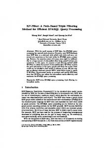
2 Motivation
Potential leakage‐savings: real versus ideal (L1: 16KB‐2 ways‐16B block) 6
62.1%
• lower performance overhead. Filtered leakage-saving architecture aims to reduce the time when cache lines are actively dissipating power. To achieve a competitive advantage in comparison to drowsy and decay cache, we propose to make lines in level 1 cache (L1) “less used” by using a filter (L0) cache [13]. This solution is very effective for the following reasons: • an L0 cache can reduce the average access time as a benefit of a better reshaped memory hierarchy; • the useless wake-up of cache lines that are in lowpower state is reduced, as many accesses hit in L0 (as showed by experiments throughout the paper); • the additional design efforts to include an L0 cache are conceptually simple. Leakage-saving caches are typically used at the first level in the hierarchy. Our findings demonstrate that not only some speed-up can be achieved by using an additional faster small cache level, but it also provides significant benefits in leakage-savings. This is due to the fact that the filter cache introduces itself negligible power consumption (it is very tiny relative to the lower level) and the usage of the lower level is reduced. The remainder of the paper is organized as follows. In the next section, we give our motivation for introducing filtered leakage-saving architecture. In Section 3, the details of our proposal are presented. In Section 4, we explain the methodology we used for our experiments. Then we discuss, in Section 5, the results we have obtained by evaluating the additional leakage savings and the performance improvements; a sensitivity analysis to some configuration parameters is presented. Section 6 illustrates some recent related works. We finally conclude in Section 7.
0 drowsy
ideal drowsy data cache
decay
ideal decay
drowsy
ideal drowsy
decay
ideal decay
instruction cache
Figure 1. Potential increment in leakage savings. The leakage energy per cycle spent in a leakage-saving cache versus the ideal case is shown. The average values across entire MiBench suite for drowsy/decay data/instruction are given with baseline configuration (Table 1).
ambitious reference point. For a drowsy cache, the best theoretical situation that can be achieved is when, during each access, only one line (the currently accessed line) is in high-power state while the others are in drowsy state. Hereafter, this case will be referred as ideal drowsy. A similar situation can be considered for a decay cache: the ideal case is when during each access only one line is in high-power state and the others are gated. Hereafter, it will be referred as ideal decay. This hypothesis is more ideal than the oracle predictor presented by Kaxiras et al. [12], where a line is turned off immediately after the last access to live data into it. They considered the limitation that the decay cache has when a line has to be awoken; here we consider possible modifications of locality too. Figure 1 shows the potential increment that could be reached with “standard” drowsy and decay. A reference configuration (16KB, 2-ways, 16B block) is shown and the values are the average leakage energy per cycle across all the benchmarks of MiBench suite [15]. The average power for two configurations is considered: the “real” cache hierarchy, where there is a level one data drowsy/decay cache (labelled in the figure as drowsy or decay), and the “ideal” situation, where a cache of the same size acts ideally (labelled in the figure as ideal drowsy or ideal decay), as described above. Details for both data and instruction cache are given. To be more precise, with reference to the baseline configuration that we use along this paper (Table 1), 511 blocks are drowsy/decay and just one is in high-power state. The leakage spent with drowsy/decay ideally can be further reduced for more than 60%. Although the leakage savings achieved with drowsy/decay techniques is considerable (more than 80% in our baseline configuration), current leakagesaving techniques are far from their theoretical maximum.
3 The filtered-power saving architecture We considered an embedded system based on an ARM XScale processor [16] and in this scenario we evaluate the filtered leakage-saving cache architecture
CPU 1 cycle
2 cycles
L0 cache (e.g.,128B-Direct Mapped-16B block)
2 cycles
L1 leakage-saving cache
L1 leakage-saving cache
(e.g., 16KB-2ways-16B block)
(e.g., 16KB-2ways-16B block)
24,4 cycles
24,4 cycles
Main Memory
Main Memory
Figure 2: Memory hierarchy with filtered leakage-saving cache. Figure shows the values for the baseline configuration and the reference latencies.
to address the problem of leakage reduction in cache memories. Many different approaches can be used to reduce leakage in caches [6] [7] [8] [9] [10] [11]. A simple solution is based on a filter cache placed between CPU and a conventional first level cache with leakage-saving capabilities (Figure 2). We call this architecture the filtered leakage-saving cache. L0 cache is a very tiny (e.g. 128B) and fast cache, therefore the latency between L0 and CPU could be, for example, 1 cycle [13]. A typical size of a L1 leakage-saving cache for embedded systems could be for example 16 KB. Due to the leakage-saving extra circuits and its larger size, this cache can experience a longer latency (e.g. 2 cycles). These values are indicative of a situation where a new cache level is added between the CPU and the leakage-saving cache. The new level is faster than the lower L1 cache, according to the memory hierarchy principle, but its size is as small as a tiny filter cache. The hierarchy is very simple, more than other structures proposed in literature. It does not have any particular promoting mechanism between L1 and L0 [17] or prediction mechanism [18]. “Conventional” leakage-saving techniques (Figure 3-a) can select the lines to put into low-power state by using many different policies [7, 19, 20]. The so called simple policy [7], the simplest one in terms of hardware additions, puts all lines into low-power state at the end of a temporal window. Newly accessed lines are woken up and remain in high-power state until the next window starts. But the aliveness of the data in such line can continue in the next window, thus implying some imprecision in the switch-off time. Other predictive techniques [12] try to approximate oracle behaviour by switching off the line at the last access to the live data into it. Intuitively, filtered leakage-saving architecture tries to achieve more than the oracle – in some cases – as it is able to switch off the line at the end of the previous window where the line is “alive”. In the filtered leakage-saving architecture (Figure 3-b),
the L0 cache captures the most recent accesses. When the “last window starts” such lines can remain in lowleakage state in L1. The filtered leakage-saving architecture aims to avoid waking up lines uselessly. The main advantages of our solution are: i) the lines in L1 get older faster (accesses can hit in L0 without waking-up lines in L1 again) thus reducing some leakage; ii) the new memory hierarchy mitigates the IPC degradation generated by a leakage-saving cache because the program execution is faster as many accesses are resolved in L0; iii) the L0 is just a simple tiny cache; if a program needs more than the size of L0, the L1 will work as a conventional leakage-saving cache, otherwise, L1 can reduce the switches between low-leakage state and high-leakage state; iv) the additional hardware cost of this solution is less than 1% of the L1 cost; moreover, L0 doesn’t have any additional circuitry for leakagesaving (such as drowsy/decay bit, voltage supply, control). Being L0 small, it introduces negligible additional power. In Figure 4, the leakage breakdown between L0 and L1 is presented. The extra leakage is almost negligible (less than 5%) and the reduction in L1 leakage is much higher. As expected, the advanteg in case of drowsy is higher than in case of decay. SWITCH-OFF WINDOW
time
Powering state
CPU
Filtered leakage-saving cache
L1
high low Useless switching operation
Wasted energy
(a) time
L0
SWITCH-OFF WINDOW
time
Powering state
Conventional leakage-saving cache
L1
high low Switching operation saved
Energy saved
(b) Figure 3: “Conventional” leakage-saving and filtered leakagesaving behaviour. (a) Behavior of “conventional” leakage-saving scheme (drowsy or decay) with simple policy. All the lines are put into low-leakage state at every temporal window. (b) Behavior of filtered leakage-saving scheme (drowsy or decay) with simple policy. Many accesses can hit directly in L0 allowing L1 to put more lines in low-leakage state.
Leakage breakdown for filtered drowsy‐cache (L1: 16KB‐ 2ways‐16B block; L0: 128B‐Direct Mapped‐16B block)
leakage (mJ/cycle)
5
4.95%
4.10%
90.07%
71.78%
4 3 2
L0 L1
1 0 drowsy
filtered drowsy
drowsy
filtered drowsy
Figure 4. Leakage breakdown for data cache. Details for filtered-drowsy data cache and instruction cache are shown given with baseline configuration (Table 1).
Moreover, in Section 5, we will demonstrate that filtered leakage-saving architecture outperforms drowsy in terms of performance.
4 Methodology 4.1. Simulation setup All simulations have been performed with HotLeakage simulator [21] for ARM based processors, as in [9] [6] [10]. We modified HotLeakage in order to implement the filtered leakage-saving architecture. The values we used for the technology are used for a 70nm process with Vdd=0.9V (Table 1) as presented in current studies [19] [6]. This choice can provide a more direct insight in comparison with such studies. However, this choice can be considered very conservative, since with newer technologies (processes smaller than 70nm) the leakage is even more significant. We used the simple policy with 4000 cycles update window. We will present results with different windows in Section 5.3. The benchmarks used are from the entire MiBench [15] suite for an ARM based processor with small input; simulations with large input have been performed too, but only a few benchmarks that differ significantly from the case of small input are presented. Simulations have also been extended to a few benchmarks from SPEC2000 suite [22] with reduced Table 1. Simulation parameters Energy configuration Leakage control technique Drowsy Decay Time for low to high switch 3 cycles 3 cycles Time for high to low switch 3 cycles 30 cycles Low to high switch cost 0.0003 nJ 0.0003 nJ High to low switch cost 0.0001 nJ 0.0001 nJ Extra latency in low leak mode 1 cycle 0 cycle Policy Simple Update window 4000 cycles Cache configuration L0 L1 Cache size 128B 16KB Block size 16B 16B Associativity Direct mapped 2 Latency 1 cycle 2 cycles Processor configuration Fetch queue (instructions) 4 Branch Predictor 8k Bimodal, 2k 4-way BTB Fetch & Decode width 1 Issue width In-order Functional units 1 int ALU, 1 FP mult, 1 FP ALU
inputs from MinneSPEC [23]. Four organizations have been used to compare filtered leakage-saving architecture (drowsy and decay) with the basic corresponding power saving scheme. To be more clear, let us consider the following acronyms: • drowsy cache: level 1 (L1) data cache without filter cache (L0); drowsy cache technique applied to L1 cache; • filtered-drowsy cache: level 1 (L1) data cache with filter cache (L0); drowsy cache technique applied to L1 cache; • decay cache: level 1 (L1) data cache without filter cache (L0); decay cache technique applied to L1 cache; • filtered-decay cache: level 1 (L1) data cache with filter cache (L0); decay cache technique applied to L1 cache; Table 1 shows the reference configuration of the caches and the parameters of the processor (modeled according to Intel XScale architecture [16]). The choice of L0 has been derived using the model proposed by Jacob et al. [24]. The total budget (B) expressed in dollars has been replaced with the power. The model has been used to find an optimal structure for the memory hierarchy, i.e. the size of L0 based on the size of L1.
4.2. Metrics analyzed Since the proposed architecture is for a low-leakage cache memory hierarchy that does not affect performance, we analyzed: • Net Power-consumption due to the LeakageSaving Technique (NPLST) to evaluate how much power we are able to save • IPC to evaluate the benefits in terms of performance For the evaluation of the NPLST, all the extra power necessary for the architecture has been taken into account, not only the intrinsic leakage power consumption of the power-saving technique (linstrinsic). In particular, the NPLST takes into account for the dynamic energy that the drowsy technique introduces. In other terms, the Net Power-consumption spent for the Leakage-Saving Technique takes into account not only the intrinsic leakage but also the contributions from activity in the counters for the update window (dynxtra), the leakage of extra circuitry (lxtra) and the extra power spent for the switches (swlh2 and swh2l): ܰܲ ܶܵܮൌ ݈௦௧௦ ݈௫௧ ݀݊ݕ௫௧ ݓݏଶ ݓݏଶ
We then evaluate the benefits of our technique by evaluating the NPLST-saving, namely the amount of Net Power-consumption that we are able to save in comparison with drowsy/decay. In addition, the NPLST for the filtered leakage-saving architecture
Increment in IPC introduced by filtered‐drowsy data cache MiBench with small input (L1: 16KB‐2ways‐16B block;L0: 128B‐DirectMapped‐16B block)
Increment in NPLST‐savings (see Section 4.2) introduced by filtered‐drowsy data cache MiBench with small input (L1: 16KB‐2ways‐16B block;L0: 128B‐DirectMapped‐16B block)
164.gzip 176.gcc 181.mcf 300.twolf basicmath tiffmedian ispell patricia
0%
% increment NPLST‐savings
Auto./indust
10%
Consumer Office Net Security Telecomm. 23.37%
Some Some MiBenc CINT20 h large 00
5%
=
Some MiBench Some large CINT2000
Telecomm.
Security
Office
Net.
Consumer
Auto./indust
0% basicmath bitcount quicksort susancorner susanedge susansmooth jpegdecode jpegencode lame mad tiff2bw tiff2rgba tiffdither tiffmedian typeset dijkstra patricia ghostscript ispell rsynth stringsearch blowfishdecode blowfishencode pgpdecode pgpencode rijndaelencode rijndaeldecode sha CRC32 FFT IFFT ADPCMencode ADPCMdecode gsmecode gsmdecode Avg. MiBenc small
5%
10% % increment in IPC
basicmath bitcount quicksort susancorner susanedge susansmooth jpegdecode jpegencode lame mad tiff2bw tiff2rgba tiffdither tiffmedian typeset dijkstra patricia ghostscript ispell rsynth stringsearch blowfishdecode blowfishencode pgpdecode pgpencode rijndaelencode rijndaeldecode sha CRC32 FFT IFFT ADPCMencode ADPCMdecode gsmecode gsmdecode Avg. MiBenc small 164.gzip 176.gcc 181.mcf 300.twolf basicmath tiffmedian ispell patricia
(b) (a) Figure 5: Filtered-drowsy data cache evaluation. The figure shows the increment in NPLST-saving (a) and the increment in IPC (b) across entire MiBench suite with small input. The baseline (0%) is the NPLST-savings of drowsy and the IPC of drowsy respectively.
takes into account also the L0 contribution: lintrinsic is the sum of the leakage spent in L0 and the leakage spent in L1. The analysis of the IPC allows a study of the performance. This metric takes into account the extra cycle that the leakage-saving technique introduces because of the accesses into low-power lines; this situation causes extra penalty cycles.
5 Results We evaluated the filtered leakage-saving architecture for both data and instruction caches separately. The MiBench [15] benchmarks with small input have been run to their completion. For a further comparison some results achieved with large input are shown, as well as selected benchmarks of SPEC2000 [22] CINT with MinneSPEC “smred” input [23].
5.1. Data cache In this section, we presents results for data cache. No leakage-saving technique is applied to instruction cache, that is 32KB. Figure 5-a shows the increment in NPLST-savings with filtered drowsy-cache. The comparison between filtered-drowsy and drowsy cache (used as baseline) is shown. In these experiments, filtered-drowsy is always better than drowsy-cache and this behaviour is maintained with large input and also with SPEC2000. Variation along the benchmarks depends on their characteristics. Globally, for MiBench with small input, the maximum improvement in NPLST-savings
(or reduction in leakage spent), in comparison with drowsy-cache, is 11.6% and in average it is about 5.3%. Changing input from small to large does not impact results so much; they remain more or less the same. Also the CINT2000 benchmarks have almost the same behaviour. The highest value achieved for 300.wolf benchmark is mainly due to its small working-set; the L0 has a high hit-rate since it captures many accesses. From these results, we can conclude that the filtered-drowsy cache architecture is a promising architecture. Figure 5-b shows the IPC. Results show 5.4% increment in average, demonstrating that the technique has benefits also for the performance. The same analysis has been done also for decay cache. Results, that are not presented due to space limitations, can be found in another paper [14]; they show that the average savings increment is lower. Decay cache itself already provides a very high leakage savings making difficult additional improvements. One of the motivations that justifies the use of the L0 cache is the reduction of useless re-wakeups of lines in L1. The average reduction of the re-wakeups is 2.5%.
5.2. Instruction cache In this section, we present results for the instruction cache. No leakage-saving technique is applied to the data caches. The technique provides significant advantages in case of L1 drowsy instruction cache. Results presented in Figure 6-a show that filter drowsy
outperforms drowsy for all MiBench benchmarks with small input. In average the increment in NPLST saving is about 25%. The same benefits are not achievable when L1 instruction cache is a decay. This is mainly due to the fact that the L0 cache is unable to hide the extra latency in which decay cache incurs when there is an access in a decayed line (this has the same latency of a miss, as it is a miss). In this case, the way in which L0 cache changes the access pattern to L1, varies the manner in which lines switch between high-power and low-power state, making the situation less favorable. Figure 6-b shows the IPC variation for instruction cache when L0 cache is coupled with a drowsy L1 cache. As shown, there is a 1.5% increment (in average). The L0 contributes in hiding the performance overhead of decay technique when it is applied to instruction caches, but it is less effective. The increment in IPC contributes in reducing the performance overhead that decay itself introduces. However the performance loss is still big versus a regular L1 cache.
5.3. Sensitivity In this section, we show the sensitivity of the results that we obtained for the above reference experiments. We have selected one benchmark from each category (namely quicksort for Automotive/Industrial, tiff2bw for Consumer, rsynth for Office, dijstra for Network, sha for Security and FFT for Telecommunication). Parameters that have been explored are the size of L0,
the size of L1 and the switch-off window size. As shown in Figure 7-a, the NPLST-savings decreases when L0 size increase. This is due to the fact that when the size of L0 increases, the extra power it introduces increases too (it is a cache that is always on); increasing the L0 size, the leakage spent in L1 doesn’t vary a lot while the additional leakage of L0 increases. Filtered leakage-savings cache architecture works well until the size of L0 is chosen correctly. If it is too big in comparison to L1, it introduces too much additional power that overrides the leakage reduction in L1. If it is too small, it is not able to filter accesses and it is useless. In Figure 7-b the sensitivity on the L1 size is shown. Filtered-drowsy works better for bigger L1, since it is able to put a bigger number of lines into the low-power state. The trend is quite linear. For very small caches, the L0 must be reduced in order to achieve better efficiency; in the opposite, the extra leakage L0 introduces is too high and it cannot be hidden by the savings in L1. Again, the size of the cache is fundamental to achieve the expected results. The behavior shown in Figure 7-c is again almost regular. The savings when the update window size varies is shown. The behavior is due to the fact that when the switch-off window size increments, the number of lines that are in low-power state decreases. In average, in the benchmarks studied, there is a 5% of reduction in the number of lines that are in lowpower state when the update window increases from 2048 cycles to 8192. This behavior underlines the fact
Increment in NPLST‐savings (see Section 4.2) introduced by filtered‐drowsy instruction cache MiBench with small input (L1: 16KB‐2ways‐16B block;L0: 128B‐DirectMapped‐16B block)
Avg. MiBench small
0% Auto./indust
40% % increment NPLST‐savings
Consumer
30%
Office Net.
20%
Security
10%
Telecomm.
Telecomm.
Security
Office Net.
Consumer
Auto./indust
0% basicmath bitcount quicksort susancorner susanedge susansmooth jpegdecode jpegencode lame mad tiff2bw tiff2rgba tiffdither tiffmedian typeset dijkstra patricia ghostscript ispell rsynth stringsearch blowfishdecode blowfishencode pgpdecode pgpencode rijndaeldecode rijndaelencode sha ADPCMdecode ADPCMencode CRC32 FFT gsmdecode gsmecode IFFT
Increment in IPC introduced by filtered‐drowsy instruction cache MiBench with small input (L1: 16KB‐2ways‐16B block;L0: 128B‐DirectMapped‐16B block) 2%
4%
6%
8% % increment in
basicmath bitcount quicksort susancorner susanedge susansmooth jpegdecode jpegencode lame mad tiff2bw tiff2rgba tiffdither tiffmedian typeset dijkstra patricia ghostscript ispell rsynth stringsearch blowfishdecode blowfishencode pgpdecode pgpencode rijndaeldecode rijndaelencode sha ADPCMdecode ADPCMencode CRC32 FFT gsmdecode gsmecode IFFT Avg. MiBench small
(a) (b) Figure 6. Filtered-drowsy instruction cache evaluation. The figure shows the increment in leakage savings (a) and the increment in IPC (b) across entire MiBench suite with small input. The baseline (0%) are the leakage savings of drowsy and the IPC of drowsy respectively.
Data cache: increment in NPLST‐savings (see Section 4.2) for filtered drowsy when L1 size changes (L0: 128B‐Direct Mapped‐16B block ‐ L1: 8/16/32KB‐2 ways‐16B block ‐ Update Window: 4000 cycles)
5%
0%
10%
Data cache: increment in NPLST‐savings for filtered drowsy when update window changes (L0: 128B‐Direct Mapped‐16B block ‐ L1: 16KB‐2 ways‐16B block ‐Update Window: 2048/4000/8192 cycles)
15%
% increment in leakage saving
10%
% increment in leakage savings
% increment in leakage savings
Data cache: increment in NPLST‐savings (see Section 4.2) for filtered drowsy when L0 size changes (L0: 64/128/256B‐Direct Mapped‐16B block ‐ L1: 16KB‐2 ways‐16B block ‐Update Window: 4000 cycles)
10%
5%
5%
0%
quicksort
tiff2bw
rsynth
dijkstra
sha
FFT
‐5%
quicksort
tiff2bw
rsynth
dijkstra
sha
FFT
quicksort
tiff2bw
rsynth
dijkstra
sha
8192
4000
2048
8192
4000
2048
8192
4000
2048
8192
4000
2048
8192
4000
2048
8192
4000
2048
8KB
32KB
16KB
32KB
8KB
16KB
32KB
8KB
16KB
8KB
32KB
16KB
8KB
32KB
16KB
32KB
8KB
0% 16KB
64B
256B
128B
256B
64B
128B
256B
64B
128B
256B
64B
128B
64B
256B
128B
64B
256B
128B
‐5%
FFT
(a) (b) (c) Figure 7. Sensitivity of the filtered-drowsy data cache. Leakage saving for data cache when L0 size varies (a), when L1 size varies (b) and when update window size varies (c) are shown.
that the introduction of the filter cache allows the policy in L1 cache to be more aggressive: a smaller update window provides benefits since the filter cache automatically provides a better selection of the lines to be switched off. As can be seen, the reference experiments performed in Section 5.1 and 5.2 are quite conservative.
6 Related work Leakage power in cache memories is more important than dynamic with current and next generation technologies [1]. New high-K materials [25] are only delaying the leakage problem, and in any case architectural solutions to cope with leakage could be usefully employed. Cache utilization varies widely across a range of applications and it varies significantly also during the execution of a single application, so there are a lot of opportunities for switching off cache lines in order to reduce leakage. Recent studies propose a better organization of the cache by reducing its size dynamically [26]. Unused lines can be put into a low-leakage state. When a cache block is put in leakage-saving state, the technique is called state-preserving if the block content is maintained and, on the other hand, non state-preserving if it is destroyed [6]. The main architectural methods of those two categories are drowsy caches [7] for the first one and cache decay [12] for the second one (see Section 1). A comparison between these two proposals has been done in [6]. After these two techniques have been introduced, many others have suggested their improvements. Petit et al. [19] proposed a drowsy cache policy called “Reuse Most Recently used On (RMRO)” that selects the lines to switch off using their usage. Our proposal shows that also with simple policy many benefits can be achieved with the addition of a filter cache. Drowsy cache approach is used with Region Based cache by Geiger et al. [9], allowing both leakage savings and no performance overhead. Li et. al [27] presented in 2002 several architectural techniques that exploit the data duplication across the different levels of cache
hierarchy. Multiple states with progressive reduction of voltage supply before the data loosing are proposed by Mohyuddin et al. [20]. Our solution is simpler since it doesn’t need many different voltage levels; moreover we present here results achieved considered all the extra effects the proposal incurs into. Meng et al. [10] explored the limit of leakage power reduction in caches and they found that, with the perfect knowledge of the access pattern, it is possible to find the exact moment when to put a line into drowsy state or when to switch it completely off. In our case, we find even better results by "off-loading" the power saving cache. Kin et al. [13] use of a tiny filter cache placed between CPU and standard cache level to reduce dynamic power. We differ from this proposal since we integrate the filter cache in a leakage-saving scenario where a cache with drowsy/decay capabilities is present. Moreover, our proposal is not intended to achieve similar results for dynamic power as in [13] but our focus here is just on the leakage, and the reader can easily derive the total effect by superposition. Our work is different from the one of Yang et al. [17], since we address the problem of leakage saving, that has increased in importance with new technology scaling. Moreover we don’t use any dynamic steering mechanism, since we would like to maintain the mechanism as simpler as possible.
7 Conclusion A filtered leakage-saving cache architecture for reducing leakage has been analyzed in detail versus drowsy and decay leakage-saving caches. The key idea is to reduce the lifetime of the lines that are in highpower state inside a leakage-saving cache. The solution is simple and effective: a tiny filter “L0” cache is placed between CPU and the first level of leakagesaving cache. The objective here is to exploit the filtering action provided by the filter cache for most recent accesses in order to allow the policy in L1 to work better. In average filtered–leakage-saving architecture
provides, for instruction cache, 24% improvement in leakage savings and 1.5% improvement in IPC relative to drowsy instruction cache; for data caches, 5% and 6% improvement can be achieved respectively. Results for decay cache show fewer benefits. A validation of the technique with some SPEC2000 benchmark has been done and also a sensitivity analysis to some configuration parameters has been presented.
8 Acknowledgments We are particularly grateful to Prof. Sally McKee form Cornell University for providing us with a modified version of HotLeakage retargeted for ARM ISA. This research is supported by the European Commission in the context of the HiPEAC Network of Excellence #004408 (FP6), the HiPEAC2 Network of Excellence #217068 (FP7) and the SARC integrated project #27648 (FP6).
9 References [1] N. S. Kim, T. Austin, D. Baauw, T. Mudge, K. Flautner, J. S. Hu, M. J. Irwin, M. Kandemir, and V. Narayanan, "Leakage current: Moore's law meets static power", in Computer, vol. 36, pp. 68-75, 2003. ISSN: 0018-9162. [2] K. Asanovic, R. Bodik, B. C. Catanzaro, J. J. Gebis, P. Husbands, K. Keutzer, D. A. Patterson, W. L. Plishker, J. Shalf, and S. W. Williams, "The Landscape of Parallel Computing Research: A View from Berkeley", in Electrical Engineering and Computer Sciences, University of California at Berkeley, Technical Report No. UCB/EECS-2006-183, vol. 18, 2006, p 56. [3] M. Powell, S. H. Yang, B. Falsafi, K. Roy, and N. Vijaykumar, "Reducing leakage in a high-performance deep-submicron instructioncache", in IEEE Transactions on Very Large Scale Integration Systems (VLSI'01), vol. 9, pp. 77-89, 2001. ISSN: 10638210. [4] J. Montanaro, R. T. Witek, K. Anne, A. J. Black, E. M. Cooper, D. W. Dobberpuhl, P. M. Donahue, J. Eno, W. Hoeppner, and D. Kruckemyer, "A 160-MHz, 32-b, 0.5-W CMOS RISC microprocessor", in Solid-State Circuits, IEEE Journal of, vol. 31, pp. 1703-1714, 1996. [5] H. Packard, "Inside the intel itanium 2 processor: an itanium processor family member for balanced performance over a wide range of applications", in White paper, Hewlett Packard, July, 2002. [6] D. Parikh, Y. Zhang, K. Sankaranarayanan, K. Skadron, and M. Stan, "Comparison of State-Preserving vs. Non-State-Preserving Leakage Control in Caches", in Workshop on Duplicating, Deconstructing and Debunking (held in conjunction with ISCA'03), pp. 14–25, 2003. [7] K. Flautner, N. S. Kim, S. Martin, D. Blaauw, and T. Mudge, "Drowsy caches: simple techniques for reducing leakage power", Annual International Symposium on Computer Architecture (ISCA'02),2002, pp. 148-157. [8] M. Powell, S.-H. Yang, B. Falsafi, K. Roy, and T. N. Vijaykumar, "Gated-Vdd: a circuit technique to reduce leakage in deep-submicron cache memories", International Symposium on Low Power Electronics and Design (ISPLED'00), Rapallo, Italy,2000, pp. 90--95. [9] M. J. Geiger, S. A. McKee, and G. S. Tyson, "Beyond Basic Region Caching: Specializing Cache Structures for High Performance and Energy Conservation", International Conference on High Performance Embedded Architectures & Compilers (HiPEAC'05), Barcelona, Spain,17-18 November 2005, pp. 102-115. ISBN: 978-3-540-30317-6. [10] Y. Meng, T. Sherwood, and R. Kastner, "Exploring the limits of
leakage power reduction in caches", in ACM Transactions on Architecture and Code Optimization (TACO), vol. 2, pp. 221-246, 2005. ISSN: 1544-3566. [11] Y. Meng, T. Sherwood, and R. Kastner, "On the limits of leakage power reduction in caches", International Symposium on High-Performance Computer Architecture (HPCA'05),2005, pp. 154-165. ISBN: 1530-0897. [12] S. Kaxiras, Z. Hu, and M. Martonosi, "Cache Decay: Exploiting Generational Behavior to Reduce Cache Leakage Power", Proceedings of the 28th annual international symposium on Computer architecture,2001, pp. 240-251. [13] J. Kin, M. Gupta, and W. H. Mangione-Smith, "The Filter Cache: An Energy Efficient Memory Structure", Annual ACM/IEEE International Symposium on Microarchitecture (MICRO'97), Research Triangle Park, NC, USA,1997, pp. 184-193. ISBN: 08186-7977-8. [14] R. Giorgi and P. Bennati, "Reducing leakage in power-saving capable caches for embedded systems by using a filter cache", ACM SIGARCH Workshop on MEmory performance: DEaling with Applications, systems and architecture (MEDEA '07), Brasov, Romania,2007, pp. 97--104. ISBN: 978-1-59593-807-7. [15] M. R. a. R. Guthaus, J.S. and Ernst, D. and Austin, T.M. and Mudge, T. and Brown, R.B., "MiBench: A free, commercially representative embedded benchmark suite", Annual Workshop on Workload Characterization (WWC'01),2001, pp. 83--94. [16] Intel, "Intel XScale Microarchitecture", in Technical Summary, 2000. [17] C. Yang and C. H. Lee, "HotSpot Cache: Joint Temporal and Spatial Locality Exploitation for I-Cache Energy Reduction", International Symposium on Low Power Electronics and Design (ISLPED'04), Newport Beach, California, USA,August 9–11 2004, pp. 114-119. ISBN: 1-58113-929-2. [18] W. Tang, A. Kejariwal, A. V. Veidenbaum, and A. Nicolau, "A predictive decode filter cache for reducing power consumption in embedded processors", 2007. [19] S. Petit, J. Sahuquillo, J. M. Such, and D. Kaeli, "Exploiting temporal locality in drowsy cache policies", Conference on Computing Frontiers (CF'05), Ischia, Italy,2005, pp. 371--377. ISBN: 1-59593-019-1. [20] N. Mohyuddin, R. Bhatti, and M. Dubois, "Controlling leakage power with the replacement policy in slumberous caches", Conference on Computing Frontiers (CF'05), Ischia, Italy,2005, pp. 161--170. ISBN: 1-59593-019-1. [21] Y. Zhang, D. Parikh, K. Sankaranarayanan, K. Skadron, and M. Stan, "HotLeakage: A Temperature-Aware Model of Subthreshold and Gate Leakage for Architects", University of Virginia Tech report, Charlottesville CS-2003-05, 2003 [22] "SPEC: Standard Performance Evaluation Corporation": http://www.spec.org, 2000. [23] A. a. L. KleinOsowski, D.J., "MinneSPEC: A New SPEC Benchmark Workload for Simulation-Based Computer Architecture Research", in Computer Architecture Letters, vol. 1, pp. 10--13, 2002. [24] B. L. Jacob, P. M. Chen, S. R. Silverman, and T. N. Mudge, "An Analytical Model for Designing Memory Hierarchies", in IEEE Transactions on Computers, vol. 45, pp. 1180-1194, 1996. [25] J. W. McPherson, "Reliability challenges for 45nm and beyond", in Annual Conference on Design Automation (DAC'06), pp. 176-181, 2006. [26] D. H. Albonesi, "Selective cache ways: On-demand cache resource allocation", in Annual ACM/IEEE International Symposium on Microarchitecture (MICRO'99), pp. 248–259, 1999. [27] L. Li, I. Kadayif, Y. F. Tsai, N. Vijaykrishnan, M. Kandemir, M. J. Irwin, and A. Sivasubramaniam, "Leakage energy management in cache hierarchies", in Parallel Architectures and Compilation Techniques, 2002. Proceedings. 2002 International Conference on, pp. 131-140, 2002.