Reducing the User Authentication Cost in Next Generation Networks Christoforos Ntantogian, Ioannis Stavrakakis
Christos Xenakis
Department of Informatics and Telecommunications University of Athens Athens, Greece {ntantogian, ioannis}@di.uoa.gr
Department of Technology Education and Digital Systems University of Piraeus Piraeus, Greece
[email protected]
Abstract—Next Generation Networks (NGN) provide multimedia services to mobile users through different access networks including WLAN. The security architecture of NGN specifies that a WLAN user must follow a multi-pass Authentication and Key Agreement (AKA) procedure, in order to get access to the IP multimedia subsystem (IMS) services. This includes a repetition of authentication steps and protocols which introduce an unnecessary overhead. This paper presents a onepass AKA procedure that eliminates the repeated steps without compromising the provided level of security. The presented procedure has minimal impact on the network infrastructure and functionality and does not require any changes to the existing authentication protocols. We investigate the induced performance improvement regarding the user authentication cost of the one-pass over the multi-pass AKA. To this end we consider a simple analytic model that quantifies the performance of onepass and multi-pass AKA. This study identifies the cases in which the one-pass AKA presents substantial benefits, e.g., when the mobile user has lengthy session time with short residence time in the service area of an access point.
N
him to the WLAN domain. In the second step, the user executes the Internet Key Exchange version 2 (IKEv2) protocol [8] that encapsulates EAP-AKA, which registers him to the 3G public land mobile network (PLMN) domain. In the third step the user using the Session Initiation Protocol (SIP) [13] executes the IMS-AKA procedure [4] for registration in the IMS domain. The multi-pass AKA procedure involves a double execution of EAP-AKA and an execution of IMS-AKA that introduce an authentication overhead [17]. This overhead is related to: (i) the exchange of messages that cause delays in users’ authentication (i.e., especially in cases that the users are located away from their home network) and consume radio resources; and (ii) the computational processing that will consume the limited energy and computational resources at the mobile devices. Therefore, the aforementioned multi-pass AKA procedure deteriorates the overall system performance and may impact negatively on the quality of service offered to the end-users.
I. INTRODUCTION
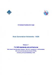
EXT Generation Networks (NGN) provide multimedia services to mobile users through different access networks including Wireless LANs (WLAN) that are capable of supporting real time applications such as video conference, video streaming, voice over IP (VoIP), etc. The provision of these multimedia services is relied on the IP Multimedia Subsystem (IMS) [3], which is based on a distributed All-IP network architecture. Along with a variety of new service perspectives and communication paradigms, NGN may raise new security concerns, mainly, because of the complexity of the deployed architecture and the heterogeneity of the employed technologies. To address the security concerns and promote the proliferation of NGN, a new security architecture is currently under study [2][4] that aims at protecting the mobile users, the data transferred and the underlying network. One of the features of this architecture specifies that a WLAN user must follow a multi-pass Authentication and Key Agreement (AKA) procedure in order to get access to the IMS services. This includes three distinct authentication steps (see Figure 1). In the first step, the user executes the (Extensible Authentication Protocol) EAP-AKA protocol [7] that registers
Figure 1: Multi-pass AKA Procedure for IMS services
There is a rather limited literature that copes with the aforementioned authentication overhead in NGN. L. Verti et al. [18] suggest an integrated authentication protocol, which is based on SIP and authenticates both the WLAN and the 3G PLMN within a single procedure, and thus reduces the overall authentication latency. However, the main drawback of this authentication procedure is that it is vulnerable to Denial of Service attacks. An adversary could simply send false authentication messages that the WLAN has to forward to the 3G PLMN causing overflow. N. Crespi et al. [19] propose the introduction of a new functional entity, called WLAN SIP proxy, in the WLAN that enables the latter to perform
localized IMS services. However, this approach requires the implementation of the new entity and the related functionality increasing the deployment complexity. This paper presents a one-pass AKA procedure for NGN that eliminates the repeated authentication steps without compromising the provided level of security. The presented procedure first combines the initial and the second authentication steps by making a security key binding between them. This binding eliminates the need for execution of EAPAKA for registration in the 3G PLMN. In the sequel, it combines the second and the third authentication steps by making a security identity binding between them. The second binding eliminates the need for execution of IMS-AKA for registration in the IMS domain, resulting in less exchange of messages and authentication computations. Therefore, the security binding mechanism improves the performance of user authentication in NGN, since it includes less security operations and messages that are exchanged between the involved nodes, compared to the multi-pass AKA. An analytic study shows that the one-pass presents greater authentication cost improvement in cases that the mobile user has lengthy session time with short residence time in the service area of an access point. Apart from reducing the authentication overhead, the presented procedure consumes less 3G authentication vectors, compared to the multi-pass AKA. The one-pass AKA has minimal impact on the network infrastructure and functionality, and does not require any changes to the existing EAP-AKA, IKEv2 and SIP protocols. The rest of this paper is organized as follows. Section 2 briefly presents the specified multi-pass AKA procedure. Section 3 describes and analyses the one-pass AKA procedure. Section 4 evaluates the performance of the one-pass and compares it with the multi-pass AKA. Finally, section 5 contains the conclusions. II. BACKGROUND A. Multi-pass AKA procedure Initial authentication for registration in the WLAN domain (step 1-Figure 1): The user and the WLAN are authenticated to each other using EAP-AKA [7] (see Figure 2). This authentication step involves the user, an Authentication, Authorization, Accounting (AAA) client that is actually a wireless Access Point (AP), and the AAA server (located at the service network) that obtains authentication information (i.e., 3G authentication vectors) from the Home Subscriber Server/Authentication Center (HSS/AuC) of the 3G PLMN where the user is subscribed, based on the user’s permanent UMTS identity (i.e., International Mobile Subscriber Identity, (IMSI)). After executing EAP-AKA, the user and the AAA server share an EAP-AKA Master Key (MK), which is used for the execution of EAP-AKA fast re-authentication and the generation of security keys [7]. The user and the AAA server use the MK to calculate the Master Session Key (MSK), and the second forwards it to the wireless AP. The AP and the user use this key to generate the WLAN session keys which are employed in the 802.11i security framework to provide security services [4]. After a successful EAP-AKA authentication, the user obtains a local IP address and can execute the IKEv2 protocol (i.e., next authentication step).
Second authentication for registration in the 3G PLMN domain (step 2-Figure 1): In this step (see Figure 3) the user and an entity called Packet Data Gateway (PDG), which is located in the 3G PLMN, execute the IKEv2 protocol [8] that encapsulates EAP-AKA for authenticating the user and the 3G PLMN. The PDG routes data traffic between a user and an external packet data network, which is selected based on the IMS services requested by the user. The IKEv2 protocol is executed in two phases (i.e., phase 1 and phase 2). In phase 1 the user and the PDG establish a bidirectional IKE Security Association (IKE_SA) that protects all the subsequent IKEv2 messages (see Figure 3- step 1).
Figure 2: The EAP-AKA protocol (First Authentication Step)
In phase 2, the user and the AAA server execute EAP-AKA encapsulated in IKEv2 messages for mutual authentication. Note that the PDG forwards the EAP-AKA messages to the AAA server using the Diameter protocol [9]. In addition, the PDG is authenticated to the user using its certificate [2] (see Figure 3- step 3). At the end of this phase the user obtains from the PDG a global IP address, called Remote IP address, which is used for access to the IMS.
Figure 3: IKEv2 with EAP-AKA (second authentication step)
Moreover, an IPsec-based Virtual Private Network (VPN) tunnel [11] is deployed between the user and the PDG that uses the Encapsulating Security Payload (ESP) [12] protocol,
which provides confidentiality and integrity to the data exchanged between them (see Figure 3 - step 4). Third authentication for registration in the IMS domain (step 3-Figure 1): After registration in the 3G PLMN domain, the user must register in the IMS domain. Mutual authentication in this step is required to avoid impersonation attacks and fraudulent IMS usage as described in [14]. Thus, in this step the user and the IMS are authenticated to each other using the IMS-AKA procedure. In IMS, multimedia services are provided by the call session control functions (CSCF) using the SIP protocol. There are three types of CSCFs: (i) a proxy-CSCF (P-CSCF) that is located in the visited network and is responsible for redirecting the SIP messages of users to their home networks; (ii) a serving-CSCF (S-CSCF) that is located in the home network of the user, communicates with the HSS and the AuC to receive IMSrelated subscriber data and authentication information, and interacts with the application servers to obtain value added services; and (iii) an interrogating-CSCF (I-CSCF) that is responsible for selecting a S-CSCF for a user.
Figure 4: IMS-AKA procedure (third authentication step)
At the beginning of the IMS-AKA procedure, the user sends its permanent IMS identity (i.e., IP Multimedia Private Identity (IMPI)) to the S-CSCF via the PDG (see Figure 4). Based on the user’s identity, the S-CSCF obtains n 3G authentication vectors from the HSS/AuC. Note that a 3G authentication vector includes a random challenge (RAND), the authentication token (AUTN), the expected response (XRES), the encryption key (CK) and the integrity key (IK). In the sequel, the S-CSCF selects one out of the n obtained authentication vectors to proceed with the IMS authentication procedure and stores the remaining n-1 for future use. Then, the S-CSCF sends the RAND and AUTN payloads to the user together with the CK and IK keys to the P-CSCF. The latter stores the CK and IK keys and forwards the RAND and AUTN payloads to the user. After receiving this information the user executes the UMTS-AKA algorithms, verifies the AUTN payload and generates the CK and IK keys. At this point, the user and the P-CSCF share the CK and IK keys and an IPsec tunnel is established between them, which protect the subsequent SIP messages exchanged (see Figure 4). Next, the user computes his response to the challenge (noted as an SRES payload), and sends it to the S-CSCF. Upon receiving this message, the S-CSCF verifies the user’s response to the challenge (SRES). If this check is successful, the S-CSCF sends a success verification message to the user to complete the third authentication step.
III.
ONE-PASS AKA PROCEDURE
A. Outline To eliminate the repeated authentication steps of the aforementioned multi-pass AKA procedure, this paper presents a one-pass AKA procedure. This procedure reduces the authentication traffic and the related computations, compared to the multi pass AKA procedure, without compromising the provided level of security. Similarly to the multi-pass AKA procedure, the one-pass AKA includes three distinct authentication steps. In the first step, the user and the WLAN are authenticated to each other performing EAP-AKA. In addition, in this step the user and the AAA server generate and store the MK key, which is used in the second step. In the second authentication step, the user is authenticated to the 3G PLMN domain by executing pure IKEv2 that omits the encapsulation of EAP-AKA. In this step the authentication of the negotiating end-points (i.e., the user and the PDG) is based on the MK key, which is generated in the first step (i.e., EAPAKA). In this way, the one-pass AKA procedure achieves a security key binding between the first and the second authentication step. In the third authentication step, the onepass AKA procedure authenticates the user by checking whether the IMPI identity and the IMSI identity belong to a legitimate user [14]. In this way, the one-pass AKA makes a security identity binding between the second and the third authentication step eliminating the need for executing the IMS-AKA for registration in the IMS domain. The one-pass AKA procedure has minimal impact on the network infrastructure and functionality, and it does not require any changes to the existing EAP-AKA, IKEv2 and SIP protocols. However, the PDG must be able to modify the SIP messages as analyzed below. Another requirement is that the PDG must be capable of retrieving the MK key, which is generated in the initial EAP-AKA authentication, from the AAA server. As mentioned in the specifications of EAP-AKA [7] and analyzed below, the AAA server stores the MK key and maintains a list that associates the user’s identities (i.e., permanent (IMSI) and temporary) with the relative MK key. Thus, the PDG can retrieve the MK key from the AAA server using the Diameter protocol. It is worth noting that there is a trusted relationship between the PDG and the AAA server, since there is a pre-established IPsec tunnel between them that protects the exchange of Diameter messages [9]. In addition, this tunnel protects the conveyance of the MK key during the execution of the one-pass AKA procedure. B. Authentication Procedure 1) Initial authentication The initial authentication step of the one-pass AKA (i.e., EAPAKA authentication between the user and the AAA server) is the same with the one of the multi-pass (see Figure 2) and starts when the wireless AP requests the user’s identity (EAP Request/identity message). The latter replies by sending to the AAA server an EAP Response/identity message, which contains either its permanent (i.e., IMSI) or a temporary identity in the format of Network Access Identifier (NAI). After obtaining the user’s identity, the AAA server checks whether it possesses a fresh 3G authentication vector, stored from a previous authentication with the specific user. If not, the AAA server sends the user’s IMSI to the HSS/AuC and
obtains n fresh 3G authentication vectors. Recall that a 3G authentication vector includes a random challenge (RAND), the authentication token (AUTN), the expected response (XRES), the encryption key (CK) and the integrity key (IK) [15]. The generation of authentication vectors is based on the pre-shared (between the user and the 3G network) secret key, K, which is assigned to the user when it is subscribed to the UMTS network. In the sequel, the AAA server selects one out of the n obtained authentication vectors to proceed with the EAP-AKA authentication procedure and stores the remaining n-1 for future use. From the selected authentication vector it uses the keys CK and IK as well as the identity of the user to compute the EAP-AKA MK (see eq.1). This key is used as a keying material to generate the Master Session Key (MSK). MK=prf(Identity| IK| CK) (1) As mentioned previously, the AAA server has to store the MK key in order to execute the EAP-AKA fast re-authentication procedure [7]. Then, the AAA server calculates a Message Authentication Code (MAC) value, denoted as MACserver, which verifies the integrity of the next EAP-AKA message (i.e., EAP-Request/AKA-Challenge). The AAA server sends the EAP-Request/AKA-Challenge message to the user, which contains the RAND, AUTN and MACserver payload. After receiving this information message, the user executes the UMTS-AKA algorithms and verifies the AUTN payload. Then, it generates the IK and CK keys, calculates the key MK, and produces the MSK key. Likewise the AAA server, the user stores the generated MK key in order to be able to execute a fast EAP-AKA re-authentication. If the verification of the MACserver value is successful, the user computes its response to the challenge (noted as an SRES payload) and sends an EAP-Response/AKA-challenge message to the AAA server that includes the SRES and a MACuser value, which covers the whole EAP message. Upon receiving the EAP-Response/AKA-challenge message, the AAA server verifies the received MACuser value and checks if the received user’s response to the challenge (SRES) matches with the expected response (XRES) of the selected 3G authentication vector. If all these checks are successful, the AAA server sends an EAP-success message along with the key MSK to the wireless AP. The latter stores the MSK key and forwards the EAP-success message to the user. Finalizing EAP-AKA, the followings have been achieved: (i) the user and the WLAN have been authenticated to each other; (ii) the user and the AAA server have stored the MK key in order to be able to perform fast re-authentications; and (iii) the user and the wireless AP share the key MSK, which is employed in the 802.11i security framework for the generation of the WLAN session keys [4]. After a successful EAP-AKA authentication, the user obtains a local IP address and executes the IKEv2 protocol (i.e., next authentication step). 2) Second Authentication In the second authentication step of the one-pass AKA, the user and the 3G PLMN are authenticated using pure IKEv2. In addition, the user and the PDG establish a VPN tunnel that protects the data conveyed between them. The IKEv2 is executed in two phases (i.e., phase 1 and phase 2). In phase 1 the user and the PDG establish a bidirectional IKE_SA that protects all the subsequent IKEv2 messages. Note that the execution of this phase is the same with the one of the multi-
pass AKA. To initiate the IKEv2 phase 1, the user sends to the PDG the SAi1 (message 1 - Figure 5) that denotes the set of cryptographic algorithms for the IKE_SA that he supports, the KEi that is the Diffie-Hellman value, and a Ni value that represents the nonce. The nonce is used as input to the cryptographic functions employed by IKEv2 to ensure liveliness of the keying material and protect against replay attacks. The PDG answers with a message (message 2- Figure 5) that contains its choice from the set of cryptographic algorithms for the IKE_SA (SAr1), its value to complete the Diffie-Hellman exchange (KEr) and its nonce (Nr). At this point, both the user and the PDG share a bidirectional IKE_SA that provides confidentiality and integrity services to the following IKEv2 messages. After the establishment of the IKE_SA, the second step of the one-pass AKA proceeds with the phase 2 of IKEv2, which authenticates the peers and establishes an IPsec_SA. In contrast to the multi-pass AKA, which re-executes EAP-AKA and uses the certificate of the PDG to achieve mutual authentication between the user and the PDG, the one-pass AKA omits these functions and the associated overhead. To accomplish mutual authentication both the user and the PDG calculate a hash value respectively (i.e., AUTHi and AUTHr payloads) using the MK key, which is generated during the execution of EAP-AKA in the initial authentication step. Then, they send to each other the AUTHi and AUTHr payloads for verification, performing a security key binding between the initial authentication step (i.e., the execution of EAP-AKA in the WLAN domain) and the second authentication step (i.e., the execution of IKEv2 in the 3G PLMN domain). To initiate the IKEv2 phase 2, the user sends to the PDG a message that includes its identity, the SAi2 payload that contains the chosen cryptographic suit for the IPsec_SA that the user supports, the traffic selectors (TSi and TSr) that allow the peers to identify the packet flows that require processing by IPsec, and the Configuration Payload Request (CPRequest) that facilitates the user to obtain a Remote IP address from the PDG and get access to the IMS services. In addition, the user includes in this message the AUTHi payload, which is a MAC value over the first IKEv2 message (i.e., message 1 Figure 5) using the stored MK key. After receiving this information, the PDG forwards to the AAA server the user identity (IDi) including a parameter, which indicates that the authentication is being performed for access to the 3G PLMN [2]. This will facilitate the AAA server to distinguish between authentications for WLAN access or for 3G PLMN access. Based on the user’s identity, the AAA server retrieves the appropriate MK key and sends it to the PDG via the Diameter protocol (message 4 -Figure 5). Recall that the MK key is conveyed in a secure manner, since there is a pre-established IPsec tunnel between the PDG and the AAA server. Upon receiving the MK key, the PDG verifies the AUTHi payload in order to authenticate the user. In the sequel, it generates the AUTHr payload by computing a MAC over the second IKEv2 message (i.e., message 2 in Figure 5) using the obtained MK key, and sends it to the user. Except for the AUTHr payload, this message also includes the PDG’s identity, the traffic selectors (TSi and TSr), the SAr2 payload that contains the chosen cryptographic suit for the IPsec_SA that the PDG supports, and the assigned user’s Remote IP
address that is included in the Configuration Payload Reply (CP-REPLY) payload. Finally, the user verifies the AUTHr payload using the MK key and authenticates the PDG. At this point the authentication in the 3G PLMN is completed and an IPsec_SA is established between the user and the PDG that provides security services to the transmitted data (see Figure 5).
IMS is successfully completed (Figure 6-message 4). Otherwise, if IMSIHSS(impi)≠imsi, then the user is not valid and his registration to IMS is discarded.
Figure 6: IMS authentication (one-pass AKA procedure)
IV. PERFORMANCE ANALYSIS
Figure 5: Second authentication step (one-pass AKA procedure)
3) Third authentication step After the authentication in the 3G PLMN domain, the user proceeds to the third authentication step that registers it to the IMS domain (see Figure 6). In contrast to the multi-pass AKA, which performs mutual authentication between the user and the IMS, the one-pass AKA procedure authenticates only the user to the IMS network. The fact that the IMS is not authenticated to the user does not imply any security risk, since IMS is located within and operated by the 3G PLMN, which has been already authenticated in the previous step. Another difference of the one-pass AKA with the multi-pass AKA is that the former does not establish an IPsec tunnel between the user and the P-CSCF. However, this does not impose any security threat, since the deployed IPsec tunnel between the user and PDG protect the messages of the SIP protocol. In the third authentication step, the user first sends a SIP register message to the PDG that includes its IMPI identity using the previously established IPsec tunnel (Figure 6-step 1). Upon receiving the user’s IMPI identity, the PDG retrieves the IMSI of the user by querying the Security Policy Database (SPD) of the IPsec protocol, which maintains the user’s profile [11]. Then, the PDG incorporates the retrieved IMSI value of the user (i.e., imsi) in the SIP register message, and forwards it to the S-CSCF (Figure 6-message 2). The latter stores the pair of identities (imsi, impi) in the user’s record, and sends the impi value to the HSS/AuC (Figure 6-message 3). Note that in case that the S-CSCF has already stored the pair of user’s identities (imsi, impi) during a previous authentication, then the exchange of messages with the HSS/AuC (Figure 6message 3) is omitted. Using the received IMPI value (i.e., impi), the HSS/AuC retrieves the IMSI identity of the user. We denote the retrieved IMSI value from the HSS/AuC as IMSIHSS(impi). In the sequel, the HSS/AuC stores the P-CSCF name and replies to the S-CSCF by sending the IMSIHSS(impi) value. Finally, the S-CSCF checks whether the received and the retrieved IMSI values (i.e., imsi and IMSIHSS(impi)) are the same. If IMSIHSS(impi)=imsi, then the S-CSCF sends a verification message to the user and the latter’s registration in
The security binding mechanism that is employed in the onepass AKA eliminates the repeated authentication steps occur in the multi-pass AKA. This improves the performance of user authentication in NGN, since the one-pass includes less security operations and messages that are exchanged between the involved nodes, compared to the multi-pass AKA. In this section we estimate the authentication cost of each procedure (i.e., one-pass & multi-pass AKA) and we compare their performance. A. System model
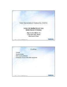
Figure 7: Time diagram of the system model
To estimate the authentication cost improvement of the onepass over the multi-pass AKA authentication procedure we consider a system model, which is analyzed bellow. Assume that a mobile user, located in a WLAN, initiates an IMS session at time t1 by executing the first, second and third authentication steps (see Figure 7). Recall that after the second authentication step, an IPsec tunnel is established between the mobile user and the PDG (see sect. 2.1 and 3.2). At time t2 and t3 the mobile user handoffs to a new access point and according to the IEEE 802.11 standard [6], it must reauthenticate in the WLAN domain. Here we consider two handover cases: (a) intra-subnet handoff and (b) inter-subnet handoff. In the former case the user moves to a new AP within the same IP subnet (see Figure 7) and performs the first authentication step (i.e., EAP-AKA). Since the mobile user remains at the same IP subnet, the current IP address of the user is valid to the new access point. Therefore, the established IPsec tunnel between the user and the PDG is maintained and the user avoids the execution of the second
and third authentication steps (i.e., IKEv2 and IMS-AKA execution respectively). On the other hand, in case of the inter-subnet handoff the mobile user moves to a new access point within a different IP subnet. Similarly to the intra-subnet handoff, the user performs the first authentication step to register in the WLAN domain. In the sequel, it must obtain a new IP address, since its current IP address is not valid in the new IP subnet. This entails the execution of the second authentication step, which establishes a new IPsec tunnel, and the third authentication step that avoids impersonation attacks and fraudulent IMS usage (see section 2.1). It is evident that the one-pass AKA procedure improves the network performance in case of inter-subnet handoff. On the other hand, in case of intra-subnet handoff both procedures (i.e., multi-pass and one-pass) present the same performance, as they employ only the first authentication step. Assume that the average number of handoffs that the mobile user performs during the IMS session is K . If the IP
Pf is the probability that a handoff session is blocked, and Re s s = p denotes the residue at a singular point s=p. Assume that the residence time of the mobile user in the serving area of an access point and the session time of the mobile user follow exponential distribution (which is a special case of Gamma distribution) with laplace transformation
f * (s) =
n µ and f c* ( −s ) = respectively. The only s+n −s+µ
singular point of f c* ( − s) is s={µ}. Therefore, eq. 2 can be simplified to: K = −n Re ss = µ
K = −n lim( s − µ ) s→µ
subnets include in average b access points uniformly distributed, then the average number of inter-subnet handoff is
K . Considering that the authentication cost for registration b
in the WLAN, 3G and IMS domains is Ac, the authentication
K cost of the inter-subnet handoffs is Ac . Including also the b
authentication cost for the initiation of the IMS session, the total authentication cost T for an IMS session is:
T = Ac +
K Ac b
(1)
To estimate the total authentication cost of the two procedures (i.e., multi-pass and one-pass AKA), we have first to estimate the average number K of handoffs performed by the mobile user and the authentication cost Ac of each procedure. 1) Estimation of K To estimate the average number K of handoffs of the mobile user, we consider a theorem from [20]. It says that assuming that the session time and the user’s residence time in the serving area of an access point follow Gamma distribution, then the average number of handoffs by the mobile user can be obtained by:
K = −n ∑ Re s s = p peσ
1 − f * ( s) f c* (− s) s 2 [1 − (1 − Pf ) f * ( s)]
(2)
*
where f ( s ) is the Laplace transformation of the PDF of the residence time of the mobile user in the serving area of an *
access point, f c ( − s ) is the Laplace transformation of the PDF of the session time of the user,
1 is the average n
residence time of the mobile user in the serving area of an * c
access point, σ is the singular point of the function f ( − s ) ,
1 − f * (s) f c* (− s ) ⇔ s 2 [1 − (1 − Pf ) f * ( s )]
K = n lim s →µ
(1 −
1−
n s+n
s 2 [1 − (1 − Pf ) n )µ s+n
n s [1 − (1 − Pf ) ] s+n 2
=
µ n −s+ µ ] s+n n
µ + nPf
⇔
⇔K =
µ n + µ Pf
(3)
1 is the mean residence time of the user in the n serving area of an access point and µ = 1 is the mean session µ time. 2) Estimation of Ac The authentication cost Ac of the one-pass and multi-pass AKA procedures can be determined considering the basic and most resource consuming communication and security activities. These activities concern: (i) the message transmission and reception within the 3G PLMN, (ii) the calculation of an authentication value using a pre-shared key for verifying a MAC, (iii) the calculation of an authentication value using public key cryptography for verifying MAC, and (iv) the encryption or decryption of a message. The notation of cost parameters for each one of the above activities is presented in Table 1. The values of the above cost parameters are taken from [21] and are consistent in the sense that these parameters can be compared with each other in the same scale. It is assumed that the encryption/decryption cost on one hop CENC is normalized to a cost unit, as it has the lightest processing load compared to the other security and communication activities. The values of the other cost parameters are determined by comparing the CENC to the time required to finish the specific communication or security activity (i.e., the ratio of the required processing time). Thus, the cost CMAC of verifying a MAC using a preshared key is two units, the cost CMAC-PKI of verifying a MAC using public key cryptography is three units and, finally, the cost CM of transmitting or receiving a message in the 3G PLMN value is 10 units (see Table 1). Where n =
Table 1: Authentication cost parameters Symbol CMAC
Description The cost of verifying a MAC using a pre-shared key
Value 2
The cost of verifying a MAC using public key cryptography
3
CM
The cost of transmitting or receiving a message in the 3G PLMN
10
CENC
The cost of message encryption or decryption
1
Using the above cost values we can calculate the authentication costs Ac of the one-pass and multi-pass AKA, by computing the partial costs of each step of the procedures. The execution of the first authentication step (i.e., the EAPAKA protocol) involves the exchange of a total of four messages between the user and the 3G PLMN, as well as the verification of the XRES and AUTN values from the AAA server and the user, respectively (see Figure 2). Recall that the first authentication step is the same in both (i.e., one-pass and multi-pass AKA) procedures. Therefore, the authentication cost of the first authentication step is 4CM +2CMAC =44. Similarly, we can compute the authentication cost of the second and third authentication steps of each procedure, and finally calculate the total authentication cost Ac for the onepass and multi-pass AKA (see Table 2). Table 2: Estimation of the authentication cost Ac of the multipass and one-pass AKA
1 Step 2 Step
One-pass AKA
Multi-pass AKA
4CM +2CMAC =44
4CM +2CMAC =44
4CM +2CENC +CMAC =46
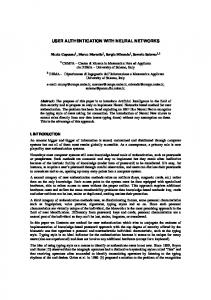
hand, as the user residence time increases and approaches or exceeds the session time, the exponential improvement becomes constant, since the mobile user performs less handovers.
900
Total authentication cost
CMAC-PKI
800
one-pass multi-pass ----------------------------Pf=0.05, b=3, 1/µ=10
700 600 500 400 300 200 100 0
5
10
15
20
25
30
Mean residence time (min)
Figure 8: Authentication cost vs. user’s residence time
Figure 9 presents the total authentication cost T of the two procedures as a function of the mean session time of the user. In case that the mean session time is relatively short, then the two authentication procedures present close cost values. Increasing the mean session time, which means that the user performs more handoffs, leads to greater differences in the authentication cost values.
8CM + 6CENC + CMAC-PKI +4CMAC =97
1600
3 Step
Ac
2CM +2CENC + CMAC =24 114
4CM +6CENC +2CMAC =50 191
B. Numerical Results Using the authentication cost values of Table 2 (i.e., one-pass and multi-pass AKA) and the formula of the average number
K of handoffs performed by the mobile user (see eq. 3), we can calculate the total authentication cost T (see eq. 1) of the
one-pass and multi-pass AKA. The calculated cost can be depicted as a function of the user mean residence time, the mean session time or the number of access points that belong to the same IP subnet. Figure 8 presents the total authentication cost T of the two procedures (i.e., one-pass and multi-pass) as a function of the user residence time. A general statement is that the one-pass AKA exhibits greater performance in terms of authentication cost, compared to the multi-pass AKA procedure. This is because it includes less security operations and messages that are exchanged between the involved nodes, compared to the multi-pass AKA. For relative small values of the user residence time, the cost improvement (i.e., the distance between the two curves) of the one-pass is greater. If the value of the mean residence time is lower from the value of the mean session time (i.e., n < µ ), then the improvement of the one-pass over the multi-pass AKA is exponential. On the other
Total authentication cost
1400
one-pass multi-pass
1200
---------------------------Pf=0.05, b=3, 1/n=5
1000 800 600 400 200 0 0
5
10
15
20
25
30
Mean session time (min)
Figure 9: Authentication Cost vs. session time
Finally, Figure 10 depicts the total authentication cost as a function of the number of access points in a subnet. As the number of access points in an IP domain is increased, the total authentication cost is reduced. This is due to the fact that the more access points belonging to the same IP subnet the less handoffs that result in the execution of the authentication procedures (i.e., multi-pass and one-pass AKA) occur (see section 4.1). The above discussion leads to a conclusion that the one-pass procedure presents a significant authentication cost improvement in cases that the mobile user has lengthy session time with short residence time in the serving area of an access point.
[4] 900
[5]
Total authentication cost
800
one-pass multi-pass ----------------------------Pf=0.05, 1/n=5, 1/µ=15
700 600
[6] [7]
500
[8]
400
[9]
300
[10] 200
[11]
100 1
2
3
4
5
6
7
8
9
10
11
12
Number of access points in a subnet
[12] [13]
Figure 10: Authentication cost vs Number of access points in an IP subnet
Apart from reducing the authentication cost, the one-pass AKA reduces the computational processing and energy cost at the level of mobile devices as well as the consumption of the radio resources. Specifically, the mobile devices avoid the computational processing and the energy consumption induced by the execution of the UMTS-AKA, and the associated UMTS security algorithms. In addition, the reduced number of messages exchanged optimizes the usage of the radio resources improving the efficiency of user authentication in NGN. Moreover, the one-pass AKA procedure consumes less 3G authentication vectors, compared to the multi-pass AKA. Finally, it avoids the deployment of a public key infrastructure, since it does not employ certificates for the PDG authentication. V. CONCLUSIONS This paper presents a one-pass AKA procedure for NGN. The security binding mechanism that is employed in the presented procedure eliminates the repeated authentication steps occurring in the multi-pass AKA. This improves the performance of user authentication in NGN, since the one-pass includes less security operations and messages that are exchanged between the involved nodes, compared to the multi-pass AKA. More specifically, the one-pass AKA improves the network performance in case of inter-subnet handoff. On the other hand, in case of intra-subnet handoff both procedures (i.e., multi-pass and one-pass) present the same performance, as they employ only the first authentication step. Moreover, the one-pass AKA presents a significant authentication cost improvement in cases that the mobile user has lengthy session time with short residence time in the serving area of an access point. Apart from reducing the authentication overhead, the one-pass consumes less 3G authentication vectors and avoids the deployment of a public key infrastructure. REFERENCES [1] [2] [3]
3GPP TS 23.234 (v7.3.0), “3GPP System to WLAN Interworking; System description”, Release 7, Sep. 2006. 3GPP TS 33.234 (v7.2.0), “3G security; WLAN interworking security; System description”, Release 7, Sep. 2006. 3GPP TS 23.228 (v8.1.0), “Technical Specification Group Services and Systems Aspects; IP Multimedia Subsystem Stage 2”, Release 8, Jun 2007.
[14] [15] [16] [17] [18]
[19]
[20] [21]
3GPP TS 33.203 (v7.6.0), “3G security; Access security for IP based services”, Release 7, Jun. 2006. IEEE Std 802.11i, “Wireless Medium Access Control (MAC) and Physical Layer (PHY) Specifications: Medium Access Control (MAC) Security Enhancements”, 2004. IEEE Std 802.11, “Wireless LAN Medium Access Control (MAC) and Physical Layer (PHY) Specifications”, 1999. J. Arkko, H. Haverinen, “EAP-AKA Authentication”, RFC 4187, Jan. 2006. C. Kaufman, “The Internet Key Exchange (IKEv2) Protocol”, RFC 4306, Dec. 2005. P. Calhoun, J. Loughney, E. Guttman, G. Zorn, J. Arkko, “Diameter Base Protocol”, RFC 3588, Sep. 2003. C. Laat, G. Gross, L. Gommans, J. Vollbrecht, D. Spence, “Generic AAA Architecture”, RFC 2903, Aug. 2000. S. Kent, R. Atkinson, “Security Architecture for Internet Protocol”, RFC 2401, Nov. 1998. S. Kent, R. Atkinson, “IP Encapsulating Security Payload (ESP)”, RFC 2406, Nov. 1998. J. Rosenberg et al, “SIP: Session Initiation Protocol”, RFC 3261, Jun 2002. Y.B. Lin, M.F. Chang, M.T. Hsu, L.Y. Wu, “One-pass GPRS and IMS Authentication Procedure for UMTS”, IEEE Journal on Selected Areas in Communications, Vol. 23, No. 6, pp: 1233-1239, Jun. 2005. C. Xenakis, L. Merakos, “Security in third Generation Mobile Networks”, Computer Communications, Elsevier Science, Vol.27, No. 7, pp: 638-650, May 2004. N. Asokan, V. Niemi, K. Nyberg. “Man-in-the-Middle in Tunneled Authentication Protocols”. Lecture Notes in Computer Science, Vol. 3364, pp: 28-41, Springer 2005. C. Xenakis, C. Ntantogian, “Security Architectures for B3G Mobile Networks”, Telecommunication Systems, Springer, Vol. 35, No. 3-4, pp:123-139, Aug 2007. L. Veltri, S. Salsano, G. Martiniello, “Wireless LAN-3G Integration: Unified Mechanisms for Secure Authentication based on SIP”, IEEE International Conference on Communications, (ICC), Istanbul, Turkey .2006. N Crespi, S. Lavaud, “WLAN Access to 3G Multimedia Services”, Infromation and Communication Technologies, (ICT), Bangkok, Nov. 2004. Y. Fang, I. Chlamtac, Y-B. Lin, “Channel Occupancy Times and Handoff Rate for Mobile Computing and PCS Networks”, IEEE Transactions on Computers, Vol. 47, No 6, pp: 679-692, Jun 1998. W. Liang, W. Wang, “On Performance Analysis of Challenge/Response Based Authentication in Wireless Networks”, Computer Networks, Elsevier science, Vol. 48 , No 2, June 2005.
ACKNOWLEDGMENT Work supported in part by the project CASCADAS (IST027807) funded by the FET Program of the European Commission, and the program “PYTHAGORAS II: Support of Universities’ research groups” co-funded by the “Operational Programme for Education and Initial Vocational Training” (O.P. “Education”) and the European Social Fund, and the 03ED910 research project, implemented within the framework of the Reinforcement Program of Human Research Manpower (PENED) and co-financed by National and Community Funds (75% from E.U.-European Social Fund and 25% from the Greek Ministry of Development-General Secretariat of Research and Technology)