ABSTRACT. As the next generation network begins to incorporate the Internet, telecommunication and TV services, it becomes one of the most critical ...
Redundant Array of Independent Fabrics -An Architecture for Next Generation Network Rongsen He and José G. Delgado-Frias School of Electrical Engineering and Computer Science Washington State University Pullman, WA, 99163 {rhe, jdelgado}@eecs.wsu.edu ABSTRACT. As the next generation network begins to incorporate the Internet, telecommunication and TV services, it becomes one of the most critical infrastructures for our society. Routers construct the skeleton of the network. Their kernel, the structure and configuration (scheduler) of the fabric, dominates the networks’ performance, scalability, reliability and cost. Based on research in [1], we proposed an interleaved architecture of multistage switching fabrics in [2], which will meet the requirements for next generation routers. In this paper, we first assess its performance with a theoretical model which complements our simulation results in [2]. Moreover, the interleaved fabrics show great tolerance against internal hardware failures. Based on these properties, we propose the architecture of RAIF (Redundant Array of Independent Fabrics) for next generation network, which could get better performance and fault tolerance as RAID [3]. KEYWORDS. MIN (multistage interconnection network), Switching fabric, Redundant Array of Independent Fabrics (RAIF).
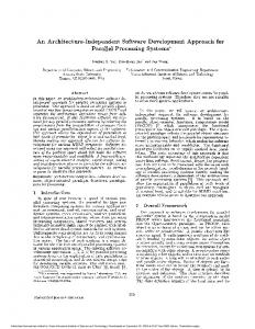
1. Introduction The advantage of packet switching with statistical multiplexing makes the convergence inevitable of the Internet, telecommunication and TV service. For example, in the past few years, Britain has updated its entire telephone network to the Internet Protocol [4]. So there is no technical difference between the telephone network and the Internet in UK. At the same time, both telecommunication carriers and cable companies provide integrated voice, video, and data service for their customers with IPTV [5], which uses IP network to deliver TV program. Thus, the incorporation of next generation network requires that a large number of line cards be integrated in a single high performance router. However, most of present routers are based on single stage crossbar, which suffers from the scalable complexity with O(N2) (N is the fabric size or input/output number). As a result, these routers only support up to 16×16 interconnection in real applications such as the Cisco 12000 high-end router. To address these issues of scalability and high performance, we proposed an interleaved architecture of switching fabrics in [2] as shown in Figure 1, which has Y panels as switching fabrics (from 1 to Y). Each panel is a N×N I-Cubeout (ICO) network (scalable with the complexity of O(N×log2N)) with recirculation to the last copy of the fabric as shown in Figure 2 [1]. The fabric is composed of b×2b switching elements (SEs), which has b remote outlets to connect to next stage and b local outlets to terminate the cells from the switching fabric to the destination queues. The Adjacent stages are interconnected according to the indirect n-cube connecting patterns such that the local SE scheduler just follows the shortest path algorithm with self-routing method as shown in [2]. If the cells fail to get
to their destination queue after the primary output (the output of the last stage), we could reenter the cells into the last copy (to avoid intensive collisions at previous copies) of next panel in modular by recirculation. Thus the recirculation flows of panel i will go to panel ((i mod Y) +1). Because the recirculated cell could get the information of availability directly from prior SE’s outlet latch indicator, we can choose the first available point (ICOFA) [1] to fed them into the switching fabrics through the multiplexers. So as shown in Figure 1, at the N inputs, N demultiplexers distribute the input traffic into each panel synchronized with a clock. At clock cycle t, all the input cells at that time will enter the panel ((t mod Y) +1). After the multiple switching fabrics are interleaved by the recirculation, the scheme provides another opportunity to balance the traffic; this in turn effectively eases the hot flows after collisions.
Figure 1. Interleaved multistage switching fabrics.
Figure 2. ICO8 with recirculation
In [2], we already demonstrate the high performance of this novel scheme by simulation under uniform and hot-spot traffic. In Section 2, we will analyze its throughput by a theoretical model for more general cases. Besides with the scalability and high performance of the interleaved architecture, its fault tolerance is still under estimated. We will evaluate its high
2763 1930-529X/07/$25.00 © 2007 IEEE This full text paper was peer reviewed at the direction of IEEE Communications Society subject matter experts for publication in the IEEE GLOBECOM 2007 proceedings.
reliability with different fault models in Section 3. Based on Section 2 and 3, we bring out the concept RAIF in Section 4. Finally, Section 5 concludes the paper. 2. Analytical model analysis In the last section, we have introduced the interleaved multistage switching fabrics. Throughput or cell drop rate (throughput =1.0−cell drop rate) is one of the most important parameters to evaluate a switching fabric. Thus, an important issue is to determine the number of panels, which are enough for a real system to obtain good throughput with a reasonable hardware cost. Here, we use our analytical model under uniform traffic to address this issue; we corroborate the model’s validity with simulation. 2.1 Analytical model for the single panel fabric Normally, it is very difficult to analyze the interleaved multistage switching fabrics if the load is non-uniform between each panel or stage. For modeling simplicity, we assume that the traffic between each panel is evenly loaded and the traffic passing from each stage to next one is uniformly distributed to each port. Moreover, we assume no buffer inside the SE between the inter-stage links. With these modeling assumptions, the complex switching system could be decomposed into each single panel with relative independence; consequently, we just need to analyze the throughput of one of them. We use the recursive method to get the analytical model for single panel fabric as [6, 7, and 8]. The load to the (k+1) stage is computed with the load that is not transferred to the output queues at the k stage. So if we know the random load starting at the first stage, we can compute the load to each stage through the whole fabric. Throughout the paper, the notations in Table 1 are used for the analytical model: Table1. Notation used in this paper. Notation Explanation X the stage number for each panel from 1 to X. Y the total number of panels from 1 to Y. N the fabric size or the input/output number. b the switching element size with b×2b crossbar. n stage number of a full fabric copy,n=logbN. Pk the load offered to stage k, and PX+1 is the load for recirculation. qk,d the load offered to stage k due to cells that have distance d to their destination queues. Ok the flow extracted from the fabric to the destination queues at stage k. Fk the load from the stage k to next stage. To keep the flow balance, Fk =Pk -Ok. p the load from outside the fabric, it also means the probability that a cell is generated to the input port during each cycle. So F0=p. π the cell drop rate of the fabric. FA
With the ICO mechanism, the cells are dropped if all the recirculation points are not available. In order to calculate the π, we need to compute the load to each stage as follows: Fk = Pk − Ok and F0 = p . (2)
Pk +1 = Fk when 1 ≤ k + 1 < X − n + 1 . (3) Pk +1 = Fk + recirculation, when X − n + 1 ≤ k + 1 ≤ X . To calculate PX-n+1 to PX with recirculation, we use a recursive expression of the form: PX −n+1 = FX −n + (1 − F X −n ) × PX +1 #
PX = FX −1 + (1− FX −1)×FX −2 ×"× FX −n × PX +1 (4) PX +1 = F X = PX − O X (5) Thus, π = PX+1 −(1− FX −n) × PX +1 −"−(1− FX −1) × FX−2 ×"× FX−n × PX +1 (6) = PX +1 × FX −1 × FX −2 × " × FX −n Moreover, each Pk for 1≤k≤X+1 is composed of qk,d with: n−1
Pk = ∑ q k ,d
(7)
d =0
To evaluate (2)-(5), it is necessary to compute the Ok first. A tagged cell in stage k can exit the fabric only if its distance becomes 0 to the destination queues. Furthermore, one of the following conditions must be met: (i) the tagged cell is the only one requiring a local outlet of the SE or (ii) more than one cell require a local outlet of the SE, but the tagged cell is chosen over the others. Then b−1 m
h m−h b−1−m Ok = qk,0 ×[ ∑ ∑ (bm−1) ⋅ (m ) ⋅ q ⋅ (P − q ) ⋅ V(h) ⋅ (1− Pk ) ] (8) h k,0 k k,0 m=0 h=0
Except the tagged cell at one SE inlet, there are other (b-1) SE inlets from which, h has cells that require local outlets with 0 distance, m-h has cells that require remote outlets to next stage with nonzero distance, and (b-1-m) has no cell for this cycle. V(h) is the probability the tagged cell is chosen in the conflict that may occur if some of the h cells require the same local h 1 1 1 (9) outlet. So V (h) = ∑ (lh )( )l ⋅ (1 − ) h − l ⋅ b b l +1 l =0 To proceed the load from Pk to Pk+1, we need the conditional probability to compute qk+1,d from qk,d distribution for d=0, 1, … , n-1.: n −1
qk +1, d = ∑ P{qk +1, d | qk , j }qk , j j =0
(10)
P{qk+1,d | qk,j}is the conditional probability that a cell has distance d in stage k+1 after it has been switched from stage k where it has distance j. Because we use the shortest algorithm with deflection scheme in the SE’s local scheduler, most of the P{qk+1,d | qk,j} parameters are zero. Depending on the different values of d, three cases are distinguished as follows for (10): (11) 1) qk +1,0 = (qk ,0 − Ok ) + P{qk +1,0 | qk ,1}q k ,1 2) qk +1, j = P{qk +1, j | qk, j +1}qk , j+1 , when 0