for example, global IP traffic is expected to increase by 3X over the next five years.[1] The .... protocols such as Ses
white paper FPGA
Finding an Efficient Virtual Network Function Architecture for Next-Generation Telecommunications Infrastructure
Beijing Research Institute
To support exponential bandwidth growth, networks need a scalable architecture that makes network functions virtualization technically and financially feasible. Authors Rajesh Narayanan
Distinguished Technologist Hewlett-Packard Enterprise
Vinay Saxena
HPE Fellow & Chief Architect CSB Hewlett Packard Enterprise
Chuck Tato
Director, Networking and NFV Business Division Intel Programmable Solutions Group
Herman Nakamura
Strategic Marketing Intel Programmable Solutions Group
Haining Wang
Senior Engineer and Project Manager China Telecom Beijing Research Institute
Bo Lei
Director of IP & Future Network Research Center China Telecom Beijing Research Institute (see Acknowledgements)
Table of Contents Introduction. . . . . . . . . . . . . . . . . . . . . . . . . . . . 1 Merging the Network and the Data Center. . . . . . . . . . . . . . . . . . . . . . . . . . . . . . . . 2 Implementing Efficient VNFs Is Critical. . . 2 CTNet2025: Transforming the China Telecom Network by 2025. . . . . . . . . . . . . 3 Toward a Highly Scalable and Efficient vBRAS Architecture. . . . . . . . . . . . . . . . . . . 4
Introduction Telecommunications service providers are facing rapidly growing usage demands; for example, global IP traffic is expected to increase by 3X over the next five years. [1] The exponential increase of mobile subscribers, Internet of Things (IoT) devices, and new services increase the complexity and cost of network build out (CapEx) and operations (OpEx). With this growing need for more bandwidth, worldwide telecommunications providers have been exploring the use of virtualization in their infrastructure to meet the demand as well as take advantage of lower-cost IT infrastructure. Current systems use proprietary hardware, which is expensive and therefore difficult to scale. IT professionals commonly use virtualization—a powerful tool for using hardware efficiently—in IT and cloud deployments to share compute infrastructure for multiple applications and thus reduce hardware costs. Service providers need a new infrastructure that uses standard servers and accelerated, virtualized network functions to balance performance and scalability needs efficiently. Network functions virtualization (NFV) has emerged as the leading transformative technology that will allow service providers to move to a truly virtualized infrastructure. There has been a lot of momentum behind NFV—with providers such as AT&T*, China Telecom*, and others exploring methods for implementing virtualization. After a great deal of work by many companies, the promise of NFV is starting to become a reality. Recognizing a need for new, unified requirements that would scale efficiently with growing traffic and services, China Telecom developed use cases and set goals for restructuring their network architecture. Based on this blueprint, Hewlett Packard Enterprise* (HPE*) and Intel®, with China Telecom's Beijing Research Institute, have developed a proof of concept for an efficient, scalable architecture that will meet the needs of next-generation networks. This white paper articulates the primary concerns facing service providers and describes an architecture to scale the virtual network function (VNF) framework that effectively addresses relative cost concerns. This architecture fosters a vendor-neutral approach and aims to usher in a new wave of cloud-native, practical VNFs supported by a diverse, rich multi-vendor ecosystem.
vBRAS Performance Results . . . . . . . . . . . . . 6 Relative Cost Savings in Efficient vBRASs.7 Comparison with Other CUPS Implementations . . . . . . . . . . . . . . . . . . . . . 8 Conclusion. . . . . . . . . . . . . . . . . . . . . . . . . . . . . . 8 References. . . . . . . . . . . . . . . . . . . . . . . . . . . . . . 9 Where to Get More Information. . . . . . . . . . 9 Acknowledgements . . . . . . . . . . . . . . . . . . . . . 9
“The global communication industry is undergoing a transformation (from a closed, vertical architecture to a horizontal, open one), bringing huge opportunities and unprecedented challenges” —China Telecom
White Paper | Finding an Efficient Virtual Network Function Architecture for Next-Generation Telecommunications Infrastructure
Merging the Network and the Data Center Providers today face several big challenges: • Despite subscriber growth plateauing, providers need to handle a huge expansion in network bandwidth. For example, due to increased demand China Telecom experienced a growth in backbone network bandwidth consumption of 42% over the past 3 years; network traffic in metropolitan areas is growing at 1.5 to 2 times the rate of backbone traffic. [2] • Subscriber demands are changing rapidly as providers face emerging use cases such as 4K TV, 8K TV, virtual reality, augmented reality, and increasingly larger on-line backup storage. • Large-scale mobility exponentially increases the business complexity because the source and destination for data and connectivity are always on the move. • IoT and advanced driver-assistance systems (ADAS) technologies are dramatically increasing the number of connected “things” as well as the volume of data being generated continuously.
models are still emerging, providers have many variables to optimize to achieve cost savings. This white paper presents how an efficient design can make NFV competitive. Although many service providers recognize the need for efficient (or cloud-native) VNFs, there is little agreement about how to develop them, and a lack of clear architectural guidelines or benchmarks. Vendors that have traditionally looked to standards bodies for guidelines are at a crossroads. The vendor community must build VNFs that are highly adaptable, easily adoptable, and simple to deploy at scale. Efficient VNFs need more than just automation and orchestration: they must at the very least beat, and preferably greatly exceed, proprietary hardware capabilities. The problem of VNF efficiency must be considered from a holistic perspective. Consider that in the first step of moving network functions from a proprietary physical implementation to a virtual function, the same system still processes the control and data planes. Although virtualization seems to improve operational problems, many virtual functions still need to process line-rate traffic. Upon analysis, three distinct focus areas emerge.
Independently Scale Control and Data Planes “A service provider’s largest core resource is the network itself.” —China Telecom
Cloud computing and virtualization emerged to address the dramatic expansion of IT capabilities efficiently. However, today, the cloud and the network do not work together flexibly. Even though cloud technologies for virtualizing compute and storage have become highly sophisticated and dynamic—and while considerable strides have been made with automating network configurations with Software Defined Networking (SDN)—network virtualization lags. Network workloads are very different from enterprise application workloads. As new applications demand high packet rates, maintaining line-rate speeds for QoS/traffic shaping, virtual private network (VPN), firewall, network address translation, encapsulation/decapsulation, deep packet inspection (DPI), real-time monitoring, and myriad other packet processing applications becomes impractical— and CapEx and OpEx prohibitive. It also directly affects the deployment of a highly dynamic virtualized infrastructure, thus slowing down the transformation of existing telecommunications networks.
Implementing Efficient VNFs Is Critical VNFs move functionality from software built for dedicated, proprietary hardware to virtualized software running on a standard server. As such, VNFs reduce the need for expensive, proprietary hardware. However, many current VNF implementations are not well optimized for the new virtual environment and offer far less performance than their traditional proprietary counterparts. While NFV, SDN, and orchestration can greatly reduce the operational complexity of deploying a telecommunications cloud, the infrastructure required to overcome the performance shortfall can be costly. A key challenge for an NFV deployment is reducing the overall CapEx and OpEx; but because cloud-based NFV
Control and User Plane Separation (CUPS) enables independent scaling of the control and data planes and is the next logical step for VNF design. While the 3rd Generation Partnership Project (3GPP) architecture defines CUPS, it is not a new concept. Telecommunications protocols such as Signaling System No. 7 (SS7) (1980) were designed with separate control and ‘bearer’ planes. Relatively newer protocols such as Session Initiation Protocol (SIP) (2002) used this concept in IP networks for Voice over IP (VoIP). The bandwidth requirements of new applications are increasing rapidly, thus, it is imperative that the data plane be resource efficient and highly scalable to avoid impeding demand growth. CUPS enables independent scaling of the control and data planes and hence is the next step to achieving a highly scalable, efficient, cost-optimized NFV infrastructure.
Optimized and Standards-Based Re-Programmable Data Planes One of the central themes of NFV is the use of standard off-the-shelf hardware platforms. While the control plane is easier to scale using standard off-the-shelf compute and memory resources, scaling the data planes to support complex packet processing at high rates can be challenging. The opportunity is to design a system where the data plane can support reconfigurable packet pipelines and complex packet processing at very high throughputs. Additionally, the data plane must perform compute intensive tasks (L4-L7 services) like QoS/traffic shaping, encryption/ “If the data center simply exists as another access node at the edge of the network, it cannot adapt to dynamic changes in network traffic flow. Without a programmable infrastructure and standardized open interfaces, it is difficult to grow capacity flexibly.” —China Telecom
White Paper | Finding an Efficient Virtual Network Function Architecture for Next-Generation Telecommunications Infrastructure
decryption, encoding/decoding, and other complex functions at line rate. CPUs can thus maintain deterministic behavior under high throughput conditions for L4 - L7 services if assisted in processing some of these tasks.
• To support 100 Gbps total aggregate bandwidth, the fabric needs six times the throughput. • Conservatively assuming each VNF only supports 25 Gbps at 100% CPU utilization, each VNF requires 4 compute nodes to support 100 Gbps.
Maximize VNF Sequestration
Thus, unoptimized VNF implementations inevitably increase CapEx and OpEx due to amplified infrastructure needs thereby increasing overall costs. Additionally, the architecture needs a load balancer to distribute the traffic at line rate to multiple vBRAS instances.
When VNFs are inefficient they move beyond the context of a single node to achieve performance targets. For example, a virtual broadband remote access server (vBRAS) contains a variety of functions: some scale easily while others benefit from acceleration. (vBRAS is also referred to as virtual broadband network gateway [vBNG].) Service chaining becomes particularly complex with many different VNF instances that need to be scaled and managed elastically. In a dynamic environment like a cloud data center, these VNFs can become dispersed intra or inter data center due to placement problems, leading to Service Function Chain (SFC) sprawl. As described in the following section, SFC sprawl further exacerbates managing, scaling, and operating an NFV infrastructure.
The example in Figure 1 highlights why providers need to architect and optimize network applications for cloud-native design. Otherwise, even if data center infrastructures allow scalable deployment and simplify management, the promise of lower relative cost may be difficult to realize.
“The goal is to eliminate the private, closed network, and create a unified hardware platform driven by business logic, software, and an open architecture.” —China Telecom
Understanding VNF Sprawl and the Need for Sequestration A vBRAS, for example, is composed of multiple VNFs such as Remote Authentication Dial-In User Service (RADIUS), Dynamic Host Configuration Protocol (DHCP), firewall (FW), DPI, and VPN functions (in addition to traffic shaping and routing). While RADIUS and DHCP add minimal compute overhead, functions such as virtual routing and traffic management that process and forward subscriber traffic operate at line rate (40 Gbps, 100 Gbps, and beyond) and hence are computationally intensive.
CTNet2025: Transforming the China Telecom Network by 2025 China Telecom’s CTNet2025 initiative [4] , announced in July 2016, envisions a network that is simple, open, cloudbased, and agile. Their vision separates network control and forwarding, decouples network hardware and software, and virtualizes the network cloud and IT, effectively moving from a closed, vertical architecture to a horizontal, open one. China Telecom has identified the following key technologies to develop their new network architecture:
A function can run on one or more CPUs in a virtual machine (VM) or container. Chaining unoptimized, and possibly sprawling, VNFs creates a heavy load on the infrastructure. Consider a SFC of vBRAS → vFW → vDPI → vVPN. The VNFs must all implement CPU-intensive packet processing like hierarchical QoS in the vBRAS. Figure 1 depicts how these VNFs would be deployed and chained in a Clos-based [3] data center. In this example, the vBRAS can incorporate a variety of functions in different permutations to support access service demands.
• Implementing SDN • Virtualizing 80% of their infrastructure by 2025 • Leveraging cloud computing technology • Using open-source software
Chaining Effect: � Traffic amplification leads to larger fabric � More compute nodes are necessary to handle the same amount of access bandwidth � Increased CapEx and OpEx
100G
200G
300G
400G
500G
600G
ToR
600 Gbps in Clos Fabric OLT
Load Balancer
OLT
Load Balancer
100 Gbps Ingress
WAN Router WAN Router
Compute Nodes
Service Function Chaining vBRAS
Figure 1. Inefficient vBRAS Deployment Example
100 Gbps Egress
FW
DPI
VPN
White Paper | Finding an Efficient Virtual Network Function Architecture for Next-Generation Telecommunications Infrastructure
VNFs that are critical to this transformation are vBRAS, virtual customer premises equipment (vCPE), virtual evolved packet core (vEPC), virtual IP multimedia subsystem (vIMS), and virtual on-line termination (vOLT).
Towards a Highly Scalable and Efficient vBRAS Architecture Design Goals China Telecom, HPE, and Intel established the following design goals to meet the needs of China Telecom’s network requirements for CTNet2025 and beyond: • Architecture—Using CUPS as the first step, the architecture must support future cloud-native design principles based on commercially available server platforms.
• Relative Cost— One of the goals of NFV is to reduce the relative cost of the overall system. As bandwidth grows rapidly, maintaining a constant cost reduction becomes challenging. This project’s design target is to show that cost savings can improve by 50% or more using a SmartNIC instead of a standard NIC, as well as provide compelling scaling for future generations.
“Our vision encompasses an NFV-driven, softwaredriven architecture that supports a fast, flexible information flow and adapts to new applications as industry needs evolve.” —China Telecom
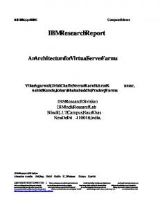
Evolution of BRAS to vBRAS The broadband remote access server (BRAS) is a common VNF that encompasses other data intensive services. Figure 2 shows the evolution of vBRASs in the context of VNF deployment in a Clos fabric: a. Physical Appliance—Legacy products consist of a physical BNG appliance in a chassis form factor. In this implementation both the control and data are implemented in the physical appliance. b. Virtualized BRAS—First-generation VNFs (including vBRASs) ported the software from a physical appliance to a virtual machine. Although the control plane workload is not too computationally intensive, the architecture
Proprietary BRAS Integrated Control and Data
c. Separated Control and Data—Recognizing the need for independently scaling the control and data planes, the vBRAS architecture described in this white paper separates the planes into separate servers. However, separating the control and data is not enough: an efficient vBRAS design must also address the data plane scaling challenges highlighted earlier.
Efficient vBRAS Design
• Power and Performance—The power budget should achieve 4 Kwatts per 1 Terabit per second (4 Kwatts/Tbps). Each node’s system must meet or exceed multi-100 Gbps.
(a) Legacy
typically suffers from data plane performance issues because data plane operations are highly parallel, repetitive, computationally intensive operations. Additionally, virtualization adds real-time software challenges.
The emerging solution (from China Telecom’s use cases and collaboration with HPE and Intel) can scale the control and data planes independently by implementing the vBRAS-c (control) and vBRAS-d (data) planes on physically separate, standard off-the-shelf server platforms. The data plane is optimized for packet processing and also accelerates computationally intensive traffic shaping and QoS functions. See Figure 3.
vBRAS-c Node The vBRAS-c node is a commercially available off-the-shelf server with a standard NIC (no acceleration) dedicated to control plane processing. Depending on the deployment needs, the user can scale the number of vBRAS-c instances up or down in the control server. The vBRAS-c design is extremely lightweight and suitable for implementation in a container. The separate control processor provides several advantages: it allows providers to add new users on demand and enables the vBRAS-c instances to become location independent. Being lightweight and virtual (in containers or VMs), vBRAS-c instances can be distributed and co-located with the data plane nodes or be centralized in the service provider’s cloud. In both cases they manage the data planes distributed in the service provider’s Central Office locations. Each vBRAS-c can control one or more data plane servers.
vBRAS-d Node The vBRAS-d is a separate server that is dedicated to packet processing (it does not handle control sessions). This arrangement enables some cores to perform only packet forwarding, while other cores perform complex packet processing functions. To further improve the server’s packet processing capabilities this novel architecture uses SmartNICs based on the Intel® Arria® 10 FPGA. An FPGA can further assist the CPU cores by performing complex packet processing functions like QoS/traffic-shaping, VPN,
(b) vBRAS Lift and Shift
(c) Separated Control and Data
Server vBRAS
vBRAS
Control Plane Server
Control Data
Control and Data
Figure 2. Evolution of vBRAS in a Clos Fabric
Control and Data
Data Plane Server
White Paper | Finding an Efficient Virtual Network Function Architecture for Next-Generation Telecommunications Infrastructure
Each Control Server (vBRAS-c) Can Control One or More Data Plane Servers (vBRAS-d) SDN Controller Northbound APIs OpenFlow
vBRAS Session Control Server vBRAS-c
vBRAS-c is implemented on a separate server (HPE DL380, 2-socket, 14 cores/socket, and 128 GB RAM).
vBRAS-c
Data Plane Server vBRAS-d is implemented on a separate server (HPE DL380) and assisted by a SmartNIC based on an Intel® Arria® 10 FPGA. Multiple FPGA cards provide scalable throughput.
vBRAS-d
vBRAS-d Control Data
Control and Data Scale Separately
Figure 3. SDN-Inspired Split vBRAS network address translation (NAT), DPI, etc. The efficient vBRAS described in this white paper uses the FPGA to accelerate QoS/traffic-shaping functions providing a level of performance and capability consistent with next-generation deployment needs. There are several advantages to an FPGA-based design. For example, in this implementation (in addition to assisting in packet forwarding), the FPGA supports line-rate QoS and hierarchical traffic shaping. The Intel® Arria® 10 FPGA provides a very powerful and reprogrammable forwarding plane. It only consumes 40% of the FPGA resources (Intel Arria 10 GT 1150) to deliver QoS and traffic shaping at 40 Gbps, leaving about 60% of the FPGA available for other network functions that require line-rate processing. The host processor can then perform other on-demand, subscriber-specific, and latency sensitive services. Because the FPGA is reprogrammable, providers can change their function as deployments differ. For instance, providers could implement proprietary or non-standard DPI algorithms on the FPGA. Additionally, providers can use the same server hardware configuration for application-specific use cases like dynamically encoding/decoding streaming content.
SDN Controller The SDN Controller is very lightweight and uses OpenFlow*[5] to configure the forwarding and QoS plane implemented by the FPGA-based SmartNIC. It controls the vBRAS-d forwarding plane only and not the state of the entire network fabric. The main advantage is to allow VNFs to be controlled
and managed independently similar to existing appliances. However, because the solution is an SDN controller based on the OpenFlow protocol, the provider can also control the vBRAS-c instances using a more centralized approach. The goal is to give the service provider flexibility when deploying the solution.
Intel Arria 10 FPGA-Based SmartNIC The Intel Arria 10 FPGA packet-forwarding design (Figure 4) can be configured for multiple parallel packet processing pipelines, each of which supports line rates of 40G/100G and beyond. The pipeline latency is similar to what would be expected from a high-performance custom ASIC/ASSP, and the flexible, scalable implementation supports internal or external buffering. The packet processing features can be enhanced or updated without deploying new hardware, which speeds up product upgrade cycles.
Vendor-Neutral Open Ecosystem Separating control and data functions on different servers is a pivotal architecture: it encourages an ecosystem in which multiple vendors contribute. The example system described in this white paper uses products from HPE and Intel, however, service providers can source vBRAS controllers and SmartNICs from various vendors (as long as the vendors follow the architecture principles described earlier). Starting with the vBRAS VNF, HPE, Intel, and China Telecom look forward to involving other SmartNIC and VNF vendors to define a standards-based API.
DDR/HBM
Packet Parser
B-Tree Look-Up n MB Cache
Look-Up DDR/HBM
Figure 4. Packet-Forwarding FPGA Design
Packet Processor
DMA
Packet Store n MB Buffer Manager
Full-Custom FPGA Pipeline Includes: � High-speed logic implementation � Deterministic access to memory � Optimal data-path widths in each block � Programming: DPDK libraries � Form factors: PCIe* Plug-in, chip on board
White Paper | Finding an Efficient Virtual Network Function Architecture for Next-Generation Telecommunications Infrastructure
vBRAS Performance Results
HPE DL380* Server(1)
Because the architecture supports separate scaling of the vBRAS-c and vBRAS-d the first setup to consider separates the vBRAS-controller and vBRAS-data planes. The software architecture is based on the design shown in Figure 3. Table 1 shows the hardware used in the testing.
vBRAS-c
HPE DL380 Server(1) vBRAS-d (Software Only)
Controller Performance Figure 5 shows a setup with a software based vBRAS-d to measure the vBRAS-c performance separately.
1. Dual-Socket, 14 Cores per Socket
Figure 5. Packet-Forwarding FPGA Design HPE DL380 Server
Scaling Control Server—Because the vBRAS software only handles session control information, it is extremely lightweight and can be packaged in containers or virtual machines (VMs). HPE’s preliminary performance testing demonstrates that each vBRAS-c node can handle 10K sessions while consuming only 11% of the CPU of a single core (out of 14 cores in a two-socket system), and just 1.5 GB RAM. Maximizing the possible number of vBRAS-c container instances, each server is projected to support more than 2.5 million sessions using 384 GB of RAM.
CPU 1
The goal of this test was to achieve 120 Gbps line rate performance with QoS. This test configured 12,000 subscriber sessions with 2 traffic classes each (high and low priority), shaping at 8 Mbps per subscriber. Generated traffic has 5 Mbps high priority and 5 Mbps low priority per subscriber (60 Gbps of high and 60 Gbps of low priority traffic total). For example, unshaped traffic is sent back at 120 Gbps (no loss) while shaped traffic is sent at 8 Mbps × 12K or 96 Gbps regardless of packet size (as configured). Different shaping parameters (8 Mbps, 8.5 Mbps, 10 Mbps) were configured to show that the total throughput (for 4,000 sessions) stays within the maximum (96 Gbps, 102 Gbps, and 120 Gbps, respectively) of all the sessions. Figure 7 shows the preliminary data plane node performance with three Intel Arria 10 FPGA SmartNIC cards. When the traffic is shaped, the high-priority traffic gets fully allocated bandwidth; the system applies shaping for low-priority traffic. Because the data plane is based on a PCIe* SmartNIC the solution can track the roadmaps defined by a diverse vendor ecosystem (the system can incorporate new SmartNICs as they become available). For example, as SmartNICs evolve,
PCIe x16
40G
40G
PCIe x16 Intel Arria 10 FPGA Card
This test studied the feasibility of using an FPGA-based SmartNIC to accelerate QoS and traffic shaping of high data rate traffic.
DPDK L2/L3 FWD
Intel Arria 10 FPGA Card
PCIe* x16
vBRAS Data Plane Performance
Data Plane Forwarding Capability—The measurements were performed on an HPE DL380*[6] server with three Intel Arria 10 FPGA-based SmartNICs as shown in Figure 6. The DL380 server is a dual-socket server with an E5-2660V3 processor per socket and 256 GB of RAM.
CPU 2
DPDK L2/L3 FWD
Intel® Arria® 10 FPGA Card
Separate Servers—A Spirent* PPPoE test generator initiates 10K PPPoE sessions, which are redirected through the vBRAS-d to the vBRAS-c server. This arrangement separates the control and data planes while preserving the session control protocol native functions without requiring tunneling mechanisms such as OpenFlow’s packet-in.
Spirent* Tester (PPPoE 10K Sessions)
40 Gbps Ethernet
40G
Spirent Tester, 3 Ports at 40 Gbps 40 Gbps, Full Duplex
Figure 6. DL380 Server Setup with 3 FPGA SmartNICs Supporting 120 Gbps with QoS and Traffic Shaping 140 120 100
Shaped to 102 Gbps
80 60 40 20 0
Shaping Enabled
Shaping Disabled
512 Bytes High Priority
Shaping Enabled
Shaping Disabled
Random 256 - 1,500 Bytes Low Priority
Figure 7. Data Plane Node Performance
White Paper | Finding an Efficient Virtual Network Function Architecture for Next-Generation Telecommunications Infrastructure
HPE anticipates doubling the potential capability of the DL380 to 240 Gbps (with traffic shaping and QoS) in 2018.
Hardware
Quantity
HPE DL380 Gen9 8SFF CTO Server
1
HPE DL380 Gen9 E5-2660v3 FIO Kit
1
HPE DL380 Gen9 E5-2660v3 Kit
1
HPE 16 GB 2Rx4 PC4-2133P-R Kit
16
HPE 600 GB 6G SAS 10K 2.5 in SC ENT HDD
2
HPE DL380 Gen9 Secondary 3 Slot Riser Kit
1
HPE Smart Array P440ar/2G FIO Controller
1
HPE 1G b Ethernet 4P 331FLR Adapter
1
Relative Cost Savings in Efficient vBRASs
HPE Ethernet 10 GB 2P 560SFP+ Adapter
6
Inefficient VNFs can magnify infrastructure needs. This white paper presents a solution that improves the economics: it accelerates complex packet processing functions using FPGA-based SmartNICs. This section discusses the system benefits including price, performance, and power.
HPE 2U SFF Easy Install Rail Kit
1
HPE 500 W FS Plat Hot Plug Power Supply Kit
2
10 GB SFP+ module
12
These initial findings indicate that the split architecture based on physically separating the control and data plane enables high controller scalability. The FPGA-based SmartNIC is also a good candidate for accelerating QoS. Additional efforts will focus on integrating the softwarebased vBRAS-d with the FPGA to achieve full vBRAS traffic throughput with QoS. The initial results are encouraging, and Intel, HPE, and China Telecom hope to share them and the integration architecture to encourage an open ecosystem.
Table 1. Hardware Configuration - Data Plane Server
It is difficult to perform cost savings calculations without clear standards or benchmarks. Therefore, to model the cost savings, this paper establishes clear goals and builds an approach based on publicly available cost models for different components.
“With NFV, device functionality is no longer dependent on expensive dedicated hardware. With inexpensive x86-based systems, operators will save equipment investment costs and can rapidly develop and deploy new applications.” —China Telecom
Model Goals and Approach
The cost is modeled with various vBRAS server capacities (50G to 200G), attempting to keep consistent server performance, and with or without the SmartNIC. The analysis shows that the performance improvement saves CPU cycles and reduces the number of cores. The charts in Figures 8, 9, 10, and 11 compare the power, server cost, system cost, and total costs for standard NICs and SmartNICs for an example system. The results are shown as a percentage of a reference bandwidth of 50 Gbps. To summarize: • The SmartNIC solution achieves a total power reduction of ~50% compared to a standard NIC server. In absolute values, the solution is well within the design goal of 4 Kwatts per Tbps. • Together, the Intel Arria 10 FPGA-based SmartNICs and commercial server CPUs optimize the data plane performance to achieve lower costs while maintaining a high degree of flexibility. • The SmartNIC provides a performance improvement per server of >3X. For higher throughputs, it exceeds the system capabilities of a single-server architecture. Using SmartNICs improves performance and supports higher throughputs at a marginal power and cost increase.
Percentage of Power (Watts)
Methodology
166% 141%
138%
100%
134%
100%
97%
38%
50 Gbps
80 Gbps
100 Gbps
Note: 1. Tested vBRAS cannot operate at this rate with QoS on.
(1)
(1)
160 Gbps
200 Gbps
vBRAS
vBRAS + SmartNIC
Figure 8. Total System Power (Watts) as a Percentage of Reference (50 Gbps)
100% Percentage of Power (KWatts)
This analysis uses constant system performance for the same workload and compares a standard NIC to a SmartNIC. It compares two dominant factors that affect cost: power and server cost. To normalize the comparison, it examines the overall cost and power of building equivalent systems to achieve same total packet throughput.
86% 71% 60% 50% 42%
38%
(1) 50 Gbps
80 Gbps
100 Gbps
Note: 1. Tested vBRAS cannot operate at this rate with QoS on.
160 Gbps vBRAS
41%
(1) 200 Gbps vBRAS + SmartNIC
Figure 9. Total Power (KWatts per 1 Tbps) as a Percentage of Reference (50 Gbps)
Percentage of 50 Gbps Reference
White Paper | Finding an Efficient Virtual Network Function Architecture for Next-Generation Telecommunications Infrastructure
241%
154%
171% 167% 142%
138%
100% 100%
127% 101%
97% 51%
75%
69% 40%
50 Gbps
135%
80 Gbps
100 Gbps
Note: 1. Tested vBRAS cannot operate at this rate with QoS on.
(1)
(1)
160 Gbps
200 Gbps
vBRAS Server Cost
vBRAS + SmartNIC Server Cost
vBRAS Energy Cost
vBRAS + SmartNIC Energy Cost
Figure 10. Total Cost of Server as a Percentage of Reference (50 Gbps) Total Cost of Energy as a Percentage of Reference (50 Gbps) after 3 Years
Percentage of 50 Gbps Reference
223%
170% 152% 128% 112%
100% 100%
95%
80%
74% 49% 49%
50 Gbps
46%
80 Gbps
Note: 1. Tested vBRAS cannot operate at this rate with QoS on.
40%
43%
40%
100 Gbps
(1)
(1)
160 Gbps
200 Gbps
vBRAS Server TCO
vBRAS + SmartNIC Server TCO
vBRAS Tbps TCO
vBRAS + SmartNIC Tbps TCO
Figure 11. Total Cost per Server as a Percentage of Reference (50 Gbps) after 3 Years Total Cost per 1 Tbps as a Percentage of Reference (50 Gbps) after 3 Years
Comparison with Other CUPS Implementations Figure 12 shows an alternate CUPS implementation of the vBRAS solution. The vBRAS control is in a standard off the shelf server but the data plane uses a proprietary chassis to preserve existing product and business investment. This solution is not open or programmable; the data plane is not available to third-party vendors, and providers cannot expand bandwidth using standard hardware. Additionally, the proprietary chassis/line-cards mean the provider risks further vendor lock-in. In contrast, this white paper introduces a pure serverbased platform in which the vBRAS-c and vBRAS-d planes scale independently. This design overcomes the limitations shown in Figure 12 because both the vendor-neutral control and data nodes are based on standard hardware. To further improve the throughput of the data plane for computationally intensive packet processing, the design uses a novel Intel Arria 10 FPGA-based SmartNIC.
Control Plane: Off the Shelf Server Data Plane: Proprietary Server vBRAS-c
vBRAS-c
Control Data
BRAS-d Proprietary Appliance
Figure 12. Alternate CUPS Implementation
White Paper | Finding an Efficient Virtual Network Function Architecture for Next-Generation Telecommunications Infrastructure
Conclusion As services have converged, network equipment has become more complex, resulting in highly specialized equipment, tightly coupled hardware and software, equipment that is difficult to scale, long upgrade cycles, and ever increasing deployment cycles for new business. In a redesigned, virtual network, service providers can draw business rules, network functions, and infrastructure from a resource pool, reducing service deployment costs and improving efficiency. This new architecture merges SDN and NFV. The cloud and network are combined, and the future data center becomes the core of the network. Moving to a fully virtualized infrastructure helps providers meet the demands of evolving markets, reduces CapEx and OpEx, and lowers overall costs.
Acknowledgements
Kumaran Siva Director, Compute and Storage Business Division Intel Programmable Solutions Group
Prodip Sen CTO, Network Functions Virtualization Hewlett Packard Enterprise Siddhartha Karkare Sr. Marketing Manager, SDN/NFV Ecosystem and Acceleration Intel Programmable Solutions Group Alexander Kugel Sr. Network Virtualization and SDN/NFV Architect Systems and Solutions Engineering Intel Programmable Solutions Group Mark Lewis Senior Manager, Network System Solutions Intel Programmable Solutions Group Frederic Richard Engineering Manager Intel Programmable Solutions Group
“With an increasing need for bandwidth, the data center must become the core of the network architecture. This change is groundbreaking and will determine the structure of all service deployments.” —China Telecom
Dekel Shirizly FPGA System Solutions Engineer, Hardware Accelerated Platforms Intel Programmable Solutions Group Shaoyang Rao, Ph.D. Deputy Director of Network Technology & Planning Department China Telecom Beijing Research Institute Fan Shi Deputy Director of CTNet2025 Open Lab Operation Office China Telecom Beijing Research Institute Hagen Woesner Co-Founder and Managing Director Berlin Institute for Software Defined Networks BISDN
References 1 2 3 4 5 6
http://www.cisco.com/c/en/us/solutions/collateral/service-provider/visual-networking-index-vni/vni-hyperconnectivity-wp.html http://www.sohu.com/a/110764570_294469?_f=v2-index-feeds http://www.networkworld.com/article/2226122/cisco-subnet/clos-networks--what-s-old-is-new-again.html http://www.c-fol.net/news/content/1/201609/20160926081545.html https://www.opennetworking.org https://www.hpe.com/us/en/product-catalog/servers/proliant-servers/pip.hpe-proliant-dl380-gen9-server.7271241.html
Where to Get More Information For more information about Intel and Intel Arria 10 FPGAs, visit https://www.altera.com/products/fpga/arria-series/ arria-10/overview.html
Cost reduction scenarios described are intended as examples of how a given Intel-based product, in the specified circumstances and configurations, may affect future costs and provide cost savings. Circumstances will vary. Intel does not guarantee any costs or cost reduction.
Intel, the Intel logo, the Intel Inside mark and logo, Altera, and Arria are trademarks of Intel Corporation or its subsidiaries in the U.S. and/or other countries. * Other marks and brands may be claimed as the property of others. © Intel Corporation.
Please Recycle
WP-01273-1.0