Insertion of the lifeguards as well as choosing an existent regression suite which fits the target selected to be refactored;. · Refactoring step;. · Testing step.
REFACTORING DIGITAL HARDWARE DESIGNS WITH ASSERTION LIBRARIES Flavio M. De Paula1, Claudionor N. Coelho Jr.2, Harry Foster3, Jose A. Nacif2 Joseph Tompkins1, Antonio O. Fernandes2, Diogenes C. da Silva Jr. 4 1 Mindspeed Technologies Inc, USA, 2CS Department. UFMG, Brazil, 3 Jasper Design Automation, USA, 4EE Department UFMG, Brazil
Abstract Refactoring is the concept of restructuring software to increase its readability and maintainability without changing the observable behavior. To the best of our knowledge, the concept of refactoring has only been applied to software development. In this paper, we describe a methodology to extend this concept into the Digital Hardware Design process using the Open Verification Library. We present a case of a network protocol bus functional model in which we want to increase the design readability so that maintenance and bug fixes are less costly.
Introduction Meeting a time-to-market requirement has become one of the most important goals in the telecommunications industry. In order to achieve that requirement, a company must maximize the reuse of old designs. In practice, reuse translates into maintaining, extending, and sometimes fixing legacy code. Based on the design life cycle and employee turnover, we can say that the same designer rarely reuses a design. Consider that each new design, on average, enters the market in two years[3]. Also, consider that during the peak of the Internet bubble, an employee stayed at the same company for an average of eighteen months[2]. Lay-offs also affect employee turnover in the hi-tech industry[22], [23],[24]. Therefore, an employee is unlikely to reuse a previous design in a next-generation product in the same company. The documentation of a specific design is usually written in a high-level descriptive language, such as pseudoalgorithms and finite-state machines. However, because it is not part of the design itself, this documentation loses its accuracy. Employee turnover, together with the lack of accurate documentation on a specific design implementation, imposes tremendous stress on the design schedule, challenging the time-to-market requirement. In this paper, we present a methodology to assist in the reuse of existing designs, providing a mechanism to
document the design and preserve its consistency as the design ages. This methodology is based on the Refactoring concept and use of Assertion Libraries. Refactoring is defined in [1] as a methodology of cleaning up code while minimizing the chances of adding bugs. It has been widely used in the software development process, especially in Object-Oriented programming (OOP). To the best of our knowledge, the concept of Refactoring has never been applied to Digital Hardware Designs. Extensive literature on OOP exists [4], [5], [6], [7] and [8]. In addition, [20] presents an OOP view of digital hardware designs. For these reasons, we do not present any detailed information regarding OOP in this paper. Here, we first present related works in the next section. We then present Refactoring concepts focused on Digital Hardware Designs followed by the case study of a network protocol bus functional model in which we increase its readability, scalability as well as its documentation, but minimize the chances of bug insertions. Finally, in the last section we conclude with our remarks and future work.
Related Work Refactoring has been widely used to extend the lifecycle of systems by providing ways to refine existing designs. These systems may only have software components as in [11] and [12], or both software and hardware components as in [13]. As another example, [14] demonstrates how to refactor distributed systems at the architectural level. However, to the best of our knowledge, no work has been published on Refactoring Digital Hardware Designs. In [14], the authors demonstrate that refactoring is not confined to programming languages. They extend refactoring to distributed systems at the architectural level. We are going to describe this work in more detail since the assumptions made in their work are conceptually similar to the work presented in this paper. The authors in [14] model a distributed system as a network of components that communicate asynchronously over buffered unidirectional channels. They describe the behavior of a system component by the relation of its input and output messages. The first assumption is that each
component is causally correct. In other words, a component output may not depend on future component input. Channel6
Channel1 Channel4 Channel2
Component1
Component3 Channel7 Channel5
Channel3
introduce and remove system components; introduce and remove component input channels; introduce and remove component output channels; replace a component by a subsystem and vice-versa and refine component behavior. In the next section, we formalize the above concepts as well as the refactoring definitions used in this paper.
Component2
Refactoring Concepts Applied To Digital Hardware Designs
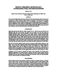
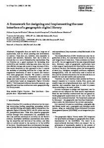
Figure 1. Message-passing System Thus, a distributed system consists of I/O channels, a set of components, and a connection structure. In Figure 1., Channel1 through Channel7 represent the I/O channels. And, Component1, Component2 and Component3 are the set of components. The second assumption is a restriction on the connection structure of the distributed system. A connection structure should not allow different components to have common outputs; each component input is either a system input or a component output; and a system output is a component output. In Figure 1., we show all possible combinations of connections within the system. Under the above assumptions, the behavior of a system is completely described by the intersection of the components’ I/O relations. By using existential quantification, one can hide the channels within two or more system components. As a result, the system can be composed hierarchically. For example, if we hide Channel4, Channel5, and Channel6, we get the hierarchical system shown in Figure 2., which can then be regarded as a component. Refactoring hierarchical systems, which can be defined by the relations of its input and outputs, can be done by refining the subset of the system’s I/O relations behavior. The rules for refining such a system are formally presented in [16]. Channel6
Channel1
Channel4 Component1
Component3
Channel 7
Channel2 Channel5
Channel3
· · · · ·
Component2
This paper focuses on applying Refactoring strategies following its definition presented in [1]. As stated in [1], “Refactoring explicitly preserves the observable behavior. This demonstrates that although refactoring primarily deals with structure, it cannot disregard behavior.” Observable behavior can take many different shapes and forms depending on to which domain it is applied. Therefore, we need to define observable behavior for a digital hardware design. In this paper, we define observable behavior as follows:
Definition 1.: Observable behavior of a design is described as a four tuple M = (S0, I, O, B), where S0 is the design’s initial state, I is a set of input sequences, O is as set of output sequences, B is a canonical function I x O which uniquely expresses the relationship between the design’s input and output histories. We extend the definition of Behavioral Refinement presented in [16] to prove that the use of a refactoring strategy in a digital hardware design model does not change its observable behavior. When refactoring a model ∆ into a unit δ, the relation between the I/O’s of ∆ must be equivalent of the I/O’s of δ. More formally:
Definition 2.: A design specification D1 is a behavioral refinement of a design specification D2, if both have the same syntactic interface, and for each input history, any output history of D2 is also an output history of D1; where syntactic interface in a digital hardware design model means the port list of the model.
Figure 2. Hierarchical Message-passing System In [17], the authors introduce a set of refactoring rules that can be applied directly to the graphical representation of the system. These rules are:
To use the above definitions, we need to capture the design intent of the system to guarantee that any model refactoring still complies with the original design. We then introduce the definition of lifeguard.
Definition 3.: Lifeguard is a set of assertions, which suffice on the characterization of the properties of the interface of a digital hardware design model. Although assertions are commonly used in the simulation and verification phases [19], [20], [21], of a system’s design, they are valuable in capturing the design intent. In this paper, the use of assertions focuses on this capability. Since refactoring is based on the re-writing of a model, one may still ask why not simply apply equivalence checking [27], [28], [29], [30] between the original and the refactored models. The reason are two fold. First, by using a set of assertions, that is the lifeguards, we desire to not only characterize the original design but also document it. The use of assertions to document a design is very powerful since it resides in the design and being always validated during a simulation. Second, once we deploy the refactored model into a new environment, one can not guarantee that the refactored model will respond properly to the new environment. By deploying the refactored model along with the lifeguards, the transition to a new environment will be easier since any violation to the design specification captured by the lifeguards will trigger a simulation error.
Case Study: A Network Protocol Bus Functional Model In this section, we present a network protocol bus functional model (BFM) used at Mindspeed Technologies [18] in which we apply refactoring techniques. We chose this BFM because it is the perfect candidate for refactoring. The design is more than five years old and yet, it is still used for testing new products. This BFM was designed to be compatible with the following telecommunication industry standard protocols: · · ·
Utopia Level 1 and Level 2; Utopia Level 1 and Level 2 extensions; Packet-extended mode of operation.
When the BFM was developed, there was not yet agreement on a Utopia Level 3, which led us to extend the Utopia levels 1 and 2 to support higher clock rates than what the standard required. We refer to them as Utopia Level 1 registered and Utopia Level 2 registered. Since there was no agreement on a packet standard at that time, we implemented a packet-extended mode version
of the Utopia protocols. This mode of operation, although very similar to the POS-PHY Level 2 [10] standard, it is not fully compliant with it. The design of the BFM intended to capture all foreseeable changes as well as configurations in one model. Unfortunately, this flexibility has a cost of making the design much more complex and expensive to maintain. Maintaining such a design may also become a daunting task when we consider the lack of up-to-date documentation and that only one engineer out of the original contributors to the design is still with the company. Scaling such design to support other protocols is also very expensive since a designer would need to go through thousands of lines of code. The concentrated knowledge of the design, its complexity, the desire of scaling it, and the lack of persistent documentation are the compelling reasons why we should refactor the design. We chose [11] as our refactoring process because its organized steps were very adequate for refactoring our BFM design. Following is the step-by-step process we used: · · ·
· ·
Analysis of the structure, flow-control and data-control followed by a documentation process on this analysis; Selection of the targets to be refactored; Insertion of the lifeguards as well as choosing an existent regression suite which fits the target selected to be refactored; Refactoring step; Testing step
Analysis and Documentation Step In this step, the goal is to make sure that the overall understanding of the code is sufficient enough to create an architectural view of the code. From this architectural view, we can document each block, the functions, and the parameters. In our BFM, we have four Verilog modules as described in the next figure. In Figure 3., the names in bold and italic represents the instance names. The names in regular type are the Verilog file and module names. As one can see, we have the same module, utopia32_bfm, representing a utx and a urx. Therefore, each phyN, where N is a number from 0 to 31, contains transmit and receive interfaces. The adrs_poll instance is responsible for polling the bus when the BFM is configured to master the bus.
phy.v uni_phy.v utopia32_bfm.v
urx adr_poll.v
utopia32_bfm.v
phy31
utx adr_poll
phy0
c_qphy0
Figure 3. BFM Block Diagram The main module of this BFM is the utopia32_bfm.v file. We start by identifying configurations, common code, and non-common code that pertains to a specific configuration. The utopia32_bfm has the following configurations implemented in it:
An object in OOP is anything that can be defined by its properties [4], [5], [6]. In this paper, we use [4] as a reference, “an object represents an individual, identifiable item, unit or entity either real or abstract, with a well-defined role in the problem domain”. Consider a test bench as our problem domain. Also, consider that a test bench comprises chips, third-party components, bus functional models, and Verilog support tasks and functions (test infrastructure). From an OOP point-of-view, each component in a test bench can be regarded as an object. In Figure 5., we represent a hierarchy structure of a test bench, where Obj_1 through Obj_5 are the objects in this hierarchy.
Obj_1
Product Family A
· · · ·
Master/Slave mode; Cell/Packet mode; Utopia Level 1 and 2, and extensions; Source of the traffic, and others.
The BFM configuration is done at the port level by setting specific values. The utopia32_bfm then chooses which code to execute based on Verilog case statements. Figure 4 shows an excerpt of the implementation. In other parts of the implementation, such as traffic generators and traffic checkers the code behaves the same way for all of the configurations. .case (MODE) CELL : case (LAYER) PHY: case (DIRECT) TX: case (LEVEL) LEVEL1: begin ... end LEVEL2 :begin ... end LEVEL2R:begin ... end RX:case (LEVEL) LEVEL1: begin ... end LEVEL2: begin ... end LEVEL2R:begin ... end ATM: case (DIRECT) TX: case (LEVEL) RX:case (LEVEL) PACKET: ....
Figure 4. Excerpt of the BFM implementation
Target Selection Step In this step, we first apply OOP concepts to our design environment so that target selections become easier to extract. We then use the information in the previous section, along with the refactoring concepts presented in [1], to select potential targets to be refactored.
Obj_2
Test Infrastructure
Obj_3
Chip Z
Obj_4
Third-Party Components
Obj_5
BFMs
Figure 5. Extending OOP to Test Bench Components Seeing the BFM as an object leads us to regard each supported protocol as a method or an attribute of the object BFM. However, the implementation does not clearly provide that notion. Rather, the implementation can be interpreted as a single method capable of supporting all protocols and configurations. This problem in refactoring terminology is called long method. Clearly, this is one target that we want to refactor. One possible side-effect of having long methods is the naming convention chosen in an implementation. For example, in Figure 4, TX and RX mean different things if the BFM is configured as master or slave. This is another target that we want to refactor. Also, each Verilog case statement, as exemplified in Figure 4, could require more than 50 lines of code. This problem in refactoring terminology is called switch statements; and this is another target we want to refactor. Having identified the targets, we want to make sure that all transformations applied to the model do not change its observable behavior. Life Guard Step In this step, we need to add a mechanism that guarantees any transformation internal to the design does not affect the
observable behavior, which is everything outside the c_qphy0 module in Figure 3. In order to lifeguard the BFM’s internal transformations, we use the Open Verification Library, which is an open-source library of assertions. We use the assertions at the interface level and for some internal flowcontrol signals. The assertions need to cover each specific protocol. Therefore, each protocol has its own lifeguard or a set of assertions. The Utopia Protocol specifications can be found in [9]. The registered version of those protocols should behave the same way as it is specified in the protocols. The only difference is that the sampling of the signals occur at the clock edges. Table 1 presents the number of assertions added per protocol. Table 1. Number of Assertions per Protocol
problem by assigning a more meaningful name to each of these modules. This methodology, although simple, generates very clear code, which is easier to debug and to interact.
Testing Step To validate the refactored BFM we chose an existing regression suite. This regression suite consists of tests for Utopia Level 1 (UL1), Utopia Level 2 (UL2) and extensions (ULr), where extensions are different bus widths and different bus clocks. The following table summarizes the results of the regression suite against the refactored BFM. Table 2. Testing Step Results Summary I
# of Errors
Protocol
a
1
All
Description Bad refactorization
# of Assertions
Protocol
b
6
UL1, UL2
Protocol violation (En_)
48 (54)
Utopia Level 1 (Utopia L. 1 registered)
c
6
ULr
Protocol violation (En_)
49 (55)
Utopia Level 2 (Utopia L. 2 registered)
d
2
UL1
Protocol violation (Addr)
e
8
All
Utopia unrelated signals
The assertions increase the confidence that we are really life guarding the BFM. However, we cannot guarantee we covered all possible scenarios with this set of assertions. This is a known problem when simulating a design [26].
Refactoring Step In this step, we choose which refactoring concept to use and apply it to the original design iteratively until we get the expected result. The refactoring concept that fits the problems described in the Target Selection Step section is the Extract Method. The Extract Method is a technique used to shorten a long, confused method. To solve the problems of having misleading naming conventions and the long method, we start by extracting each protocol along with the code that is responsible for the BFM behavior as master modes and as slave modes. We then take into account the implementation of the transmit and receive sides for each of the above modes. By iteratively applying the above methodology to each section of the BFM code, we extract twelve Verilog modules. The reason for twelve modules stems from having three protocols, –actually, the Utopia Level 1 registered is the Utopia Level 2 registered configured as a single phy– two directions and two mastership modes. These modules are then instantiated in the utopia32_bfm.v file. Although it seems we are replicating code, those twelve modules have distinct protocol implementations. As a result, one needs only to look at a specific module to debug a problem or understand a behavior. We solve the naming convention
In Table 2., index b refers to the RxEn_ and TxEn_ ATM Layer signals being de-asserted before the end of the transmission while the ATM Layer is still reading data from the bus. Index c refers to the same errors as in b. However, these might be regarded as feature of these extended protocol versions. Index d refers to the PHY Layer behavior being affected by the address lines in the bus. Index e refers to existing signals on the BFM to support a proprietary packet protocol. Since this design is more than five years old, we anticipated that some implementation details were lost over time. We believe the majority of the errors reported in Table 2 are the result of loosing that knowledge. These results show the value of this technique, which guarantees the portability of the design by capturing the intended behavior of the design’s interface via the use of lifeguards. On the other hand, if we have used equivalence checking to validate the refactored design we would not catch the protocol violations cited in Table 2. Moreover, we would not be able to guarantee a portable design. The reason stems from the fact the equivalence checking would be only validating the design itself.
Conclusions Refactoring is a transformational methodology of existing code. To the best of our knowledge, this
methodology has only been applied to software development. We presented a methodology of using assertion libraries as a mechanism to ensure that the observable behavior is not affected. We presented a case-study of a refactored bus functional model. By refactoring that model, we provided a more readable and maintainable model. We also improved its scalability. In addition, we uncovered twenty-two bugs in the original design. We also shown the value of this technique compared to other transformational coding methodologies such as equivalence checking. However, we found that this technique has a limitation. We cannot guarantee total coverage when adding the lifeguards. To solve this limitation, in future work, we will add functional coverage [25] using the lifeguards as a starting point to provide means of measuring how much more lifeguarding is needed. Also, we will pursue the refactoring of the other protocols of this bus functional model.
References [1] Fowler, M. Refactoring: Improving the Design of Existing Code. Addison-Wesley Object Technology Series, Printing July 2002.
[14] Philipps, J., Rumpe, B. Roots of Refactoring, 10th OOPSLA Workshop on Behavioral Semantics, 2001, USA [15] Gamma, E., et al, Design Patterns: Elements of Reusable Object-Oriented Software, Addison-Wesley, 1994 [16] Broy. M., St∅len, K, Specification and Development of Interactive Systems – Focus on Streams, Interfaces and Refinement, Springer-Verlag New York, Inc. – 2001 [17] Philipps, J. Rumpe, B., Refinement of Pipe and Filter Architectures, FM’99, LNCS 1708, pages 96-115, 1999 [18] From the world-wide-web: http://www.mindspeed.com [19] H. Foster, "Improving Verification through Property Specification", D&R Industry Articles [20] L. Bening, H. Foster, Principles of Verifiable RTL Design, Kluwer Academic Publishers, 2001 [21] Foster, H. and Coelho, C., “Assertions Targeting a Diverse Set of Tools” International HDL Conference, 2000 [22] From the world-wide-web: http:// www.ecommercetimes.com/perl/story/20434.html [23] From the world-wide-web: http:// www.ecommercetimes.com/perl/story/21226.html
[2] From the world-wide-web: http://news.com/2100-1017-241914.html?legacy=cnet
[24] From the world-wide-web: http:// money.cnn.com/2003/07/02/news/economy/jobs_walkup/ index.htm
[3] From the world-wide-web: http://zdnet.com/2100-1103-942688.html
[25] Foster, H., Krolnik A., Lacey D., Assertion-Based Design, Kluwer Academics Pub. 2003
[4] Grady Booch. Object-Oriented Analysis And Design With Applications, 2nd Ed. Benjamin Cummings. ISBN 08053-5340-2.
[26] M. Kantrowitz and L. Noack. I’m done simulating; now what? Verification coverage analysis and correct-ness checking of the dec chip 21164 alpha microprocessor. In Proceedings of Design Automation Conference, pages 325330,1996
[5] Cox, Brad J. Object-Oriented Programming, An Evolutionary Approach. Addison Wesley. [6] James Martin and James J. Odell. Object-Oriented Analysis and Design, Prentice-Hall, Englewood Cliffs, NJ. [7] Stroustrup, B. The C++ Programming Language (3rd edition). ISBN 0-201-88954-4 [8] Rumbaugh James, et al. Object-Oriented Modeling and Design. Prentice Hall [9] From the world-wide-web: http://www.atmforum.com/ [10] From the world-wide-web: http://www.oiforum.com. [11] Lee, Jong-Ho et al. Object-Oriented Refactoring Process Design for The Software Reuse, ISIE 2001, Korea [12] Mehta, A., Heineman, G. T., Evolving Legacy System Features into Fine-Grained Components, ICSE 2002, USA [13] Mancl, D. Refactoring for Software Migration. IEEE Communications Magazine, October 2001
[27] Pixley, C., Introduction to a Computational Theory and Implementation of Sequential Hardware Equivalence. In Proceedings of Computer-Aided Verification, pages 54-64, 1991 [28] Madre, J.C, Bilon, J.P, Proving Circuit Correctness Using Formal Comparison between Expected and Extracted Behavior, In Design Automation Conference, Pages 205210, 1988 [29] Matsunaga, Y., An Efficient Equivalence Checker for Combinational Circuits. In Proceedings of Design Automation, pages 629-634, 1996 [30] Zhou, Z., Burleson W., Equivalence Checking of Data paths Based on Canonical Arithmetic Expressions. In Proceedings of Design Automation Conference, pages 546551, 199