hardware assertion checkers for inclusion into efficient .... verification tools (static verification) and by simulation ..... design hierarchy for monitoring. 5.
Incorporating Efficient Assertion Checkers into Hardware Emulation Marc Boul´e and Zeljko Zilic McGill University, Montr´eal, Canada {mboul, zeljko}@macs.ece.mcgill.ca Abstract Assertion–based verification (ABV) is emerging as a paramount technique for industrial–strength hardware verification, especially through the emerging Property Specification Language (PSL). Since PSL introduces significant overhead to simulators, in this paper we present the infrastructure for hardware emulation capable of supporting ABV. We develop a tool that generates hardware assertion checkers for inclusion into efficient circuit emulation. The MBAC checker generator is outlined, together with the algorithms for optimized assertion–circuit generation. Experiments show that MBAC outperforms the best known checker–generator.
1. Introduction The ever–increasing complexity of integrated circuits requires a powerful verification methodology as a key to increased productivity and design quality, as well as a shorter time to market. Verifying that the implementation of a given circuit correctly performs its intended behavior is by itself a complex task that can be tackled in a number of ways. Assertion–Based Verification (ABV) is the modern verification paradigm that is equally suitable across the spectrum of formal verification and simulation–based approaches. The assertion is a verification directive that requires that a certain property be respected by the Design Under Verification (DUV). The Property Specification Language (PSL) [2, 3] is quickly emerging as the key Hardware Verification Language (HVL), and is undergoing IEEE standardization through the IEEE 1850 working group. One of the goals of PSL is to offer means of capturing specification (design intent) formally and at a higher level of abstraction than the standard Hardware Description Languages (HDLs). With formally defined syntax and semantics, PSL allows designers or verification engineers to model the proper behavior of a given design module in a clear, unambiguous manner. These
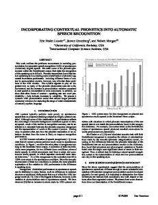
specifications are then used by the verification tools during the verification process. Verification can be formally performed by automated theorem provers or model checkers, which check all valid inputs and computation paths. Because of state explosion issues, formal methods usually scale worse than the simulation approaches. The prevalent verification method hence involves simulating a sufficiently large set of test vectors, or testbenches to ensure proper behavior. When simulation times become excessive, designers often resort to emulation, mostly using programmable– logic devices such as FPGAs. It is apparent that assertion–based verification introduces significant overhead to the simulation procedure. For a large circuit, in addition to simulating the bare circuit, a large number of fairly complex assertions have to be simulated and checked as well. For this reason, the use of hardware emulators in ABV is especially appealing. Rather than adding the assertions in series to the simulator execution, they can be handled in parallel to the circuit under verification. To address such a real need to incorporate assertions into the emulation process, a hardware–checker generator is needed to transform the PSL statements into efficient HDL code that can be seamlessly included with the DUV. This paper presents the tool that addresses both the performance and usability of hardware–supported ABV. Figure 1 shows an example in which a logic assertion related to the input/output signals of a counter is realized by an added circuit that can be emulated in hardware. Without checking the assertion, a design error in the DUV could affect blocks much further downstream and many clock cycles later. By improving observability, assertions provide the possibility of detecting faults exactly where they appear and can therefore ease the debugging process considerably. The high–level expressive power of PSL, when used with the checker generator, alleviates the need to design assertion circuits explicitly in the HDL; manually writing and maintaining checkers can be a demanding process [1]. PSL assertions are starting to be incorporated into
load en_load en_ud up_ndown clk reset HDL
Up-down counter (DUV)
D
Assertion compiler
HDL
cnt
= D
assert always (prev(en_load) == 1) -> (cnt == prev(load));
PSL
Figure 1. Incorporating an assertion to hardware emulation.
some simulators, such as Mentor Graphics’ ModelSim. Synopsys’ VCS can handle many assertions such as System Verilog Assertion (SVA) and verification libraries, however, PSL is not supported. Research is also being performed to incorporate assertions to the SystemC modeling environment [4, 6, 10]. The process of transforming PSL into HDL code has been recently accomplished by IBM–AlphaWorks’ FoCs property checkers generator [1, 7]. However, as will be observed in Section 5, this tool is not ideal for emulation purposes, as not all of the circuits it produces are synthesizable. Furthermore, many important constructs are not handled by FoCs. Experiments also show that more work is needed in order to attain minimal resource usage for assertion circuits. A comparison with the 0–in Assertion Compiler [8] was not possible because the tool is not freely available, and no details are made public. In this paper we present the development of MBAC, a hardware–checker generator specialized for use in the context of emulation. Section 2 overviews PSL and discusses the use of a checker generator. In Section 3, the mapping of PSL assertions to a target HDL is presented. The MBAC checker generator is also introduced. Section 4 discusses how assertion circuits are used in the context of hardware emulation, and shows an example application of hardware assertions. Experimental results are presented in Section 5.
2. The Property Specification Language The Property Specification Language allows designers to formally capture design specifications and properties for use in the verification process. This language was built upon IBM’s Sugar language and was introduced to the wider design community by Accellera. The Language Reference Manual [2] is currently the main
reference for the syntax and semantics of PSL. PSL allows specifications to be used both by formal verification tools (static verification) and by simulation tools (dynamic verification). In formal verification, no stimulus is required and properties are evaluated mechanically. For example, one could state the property that in any possible path rooted at a given state, the idle state is reachable. Such branching–time logics are obviously not simulatable and for this reason, the simple–subset [2] of PSL is often used in place of the full language. In the simple subset, operators such as “∀ paths” and “∃ path” are disallowed. Hence there is only one path through future states, and in our context, it is imposed by the testbench or the environment. Formal methods, however, have many applications, even making their way into the System–On–Chip domain [11]. In this paper, the intended use of the assertions is for hardware emulation, therefore the presentation and usage of PSL will be in the context of the simple subset. For PSL to be widely applicable, four different flavors are supported by use of flavor macros [2]: VHDL, Verilog, SystemVerilog and GDL. Because the initial version of the checker generator presented in this paper uses Verilog syntax, the Verilog flavor of PSL will be used throughout. For brevity, we present herein a subset of PSL constructs. All PSL expressions will be implicitly clocked to the default clock using the following PSL directive: default clock = (posedge clock sig ); In PSL, the Boolean Layer is comprised of the expressions of the underlying HDL, to which Boolean implication (–>), equivalence () and built–in functions are added. Built–in functions include: • prev(sig) and prev(sig, N ): returns the previous value of the sig signal, one clock or N clocks previous to the current cycle; • stable(sig), rose(bit), fell(bit): behavior of a bit value compared to its previous value, returns a Boolean. stable() also allows bit–vector arguments. While many relevant assertions can be built using the Boolean layer, the expressive power of PSL comes from the Temporal Layer. The main construct in the Temporal Layer is the sequence. A sequence is a regular expression that can be seen as a list of Boolean expressions or other sequences that occur in successive clock cycles. A sequence is enclosed in curled braces {}. The list separator is a semicolon. The colon can also be used to fuse sequences together, in which case the last cycle of the left–hand sequence overlaps with the first cycle of the right–hand sequence. For example, in simulation context, the sequence:
{req == 1; ack == 1; req == 0} evaluates to true in the current cycle if req is 0, and in the previous clock cycle ack was asserted and prior to that, req was asserted. PSL sequences are somewhat similar to those found in the e Language and in SVA. The repetition operator [∗n] can also be used to construct a sequence, and can be applied to a Boolean expression or another sequence. A range of numbers [∗l:h] can also be specified for the repetition. Sequences can be used with the suffix implication operators: • Sa |=> Pb : if sequence Sa is true, then property Pb must start on the cycle after Sa finishes (a sequence is a type of property). When the Sa precondition is true, the implication fails on the first cycle in which Pb fails. If sequence Sa is false, then the resulting suffix implication is vacuously true. • Sa |–> Pb : same as |=> except that the last cycle of Sa overlaps with the first cycle of Pb . A property is constructed with statements from the Temporal and Boolean Layers. To add more temporal control over how properties should behave during execution, simple temporal operators can be used: • always X: property X must always be true; • never X: property X must never be true; • next X: property X must be true in the next cycle; • eventually! X: property X must eventually be true. A simple temporal operator and its property are also considered a property. The eventually! has a “!” to indicate it is a strong temporal operator. This means that the property must eventually hold and must do so before the end of execution. It should be noted that Boolean implication is also part of the Temporal Layer, because it also allows a property as the right–hand side. In general, the verification methodology involves writing properties that should be respected by the design under verification. The assert verification directive is used to express the fact that a given property must be verified. An example for watchdog verification is shown in Figure 2. The statements are grouped into the vunit (verification unit) vu1, which is bound to the HDL module entitled circuit. Hence, all the local signals used in the circuit can be used in the vunit for constructing PSL statements. The watchdog example shows an assertion and how it can be used to verify one of the correctness properties of the given circuit. This is the key principle at the foundation of assertion–based verification. In this paper, the term assertion is used to describe the verification
vunit vu1(circuit) { default clock = (posedge clock); property watchdog works = always {(∼active)[*10]} |=> {watchdog==1}; assert watchdog works; } //vu1
Figure 2. Watchdog verification example. statements as they appear in PSL form. The term assertion circuit is used to describe the same assertions, once they are transformed into HDL form. An assertion signal is the output of an assertion circuit or of a simulation kernel’s implementation of an assertion. It is this signal which is monitored during an emulation or simulation run. If an execution terminates and no assertion signals fired, then all is working properly. It is important to keep in mind, however, that verification is only as powerful as the assertions that are used. The signal resulting from an assertion circuit behaves according to the following assertion–polarity definition. Definition 1: assertion polarity. The assertion polarity defines the meaning of the logic–level of an assertion signal. The assertion signal is at logic–0 when its property is true, and is asserted when the property fails. The polarity of the PSL assertion is thus inverted relative to the trueness of the property. In assertion semantics, assertions are meant to catch failures. Hence, a property that evaluates to true (asserted) corresponds to an assertion that is deasserted, and vice–versa. In the experimental component of this paper, the assertion distance is used for comparison purposes. Definition 2: assertion distance. For two given traces of assertion signals, the assertion distance is defined as the number of clock cycles in which the two assertion signals disagree. The signals in question are typically from two different implementations of the same PSL assertion. If many assertions are being compared, the distance is the sum of the distances between each pair of assertion signals.
3. Generating Assertion Circuits Incorporating assertions into hardware emulation involves transforming the PSL statements into a hardware language description suitable for inclusion into the DUV. All the concepts described in this section were implemented in our checker generator called MBAC. Each vunit in the PSL file must be bound to a module from the source design. The generator produces a file which contains one Verilog module corresponding to each vunit in the PSL file. These modules are referred to as assertion–circuit modules. The source file of the DUV is supplied as input to the tool in order
to facilitate the automatic generation of the following aspects: automatic detection of signal dimensions to avoid having to write signal–mapping files; replication of used functions’ declarations so that they may be used in the PSL statements; replication of parameter declarations thereby allowing parameterized assertions to generate parameterized assertion–circuits. The interface of an assertion–circuit module is comprised of the following signals: an output vector of assertion signals; inputs for each signal, clock or integer referred–to in a vunit; and a reset signal to properly initialize FFs (flip–flops) present in the generated code. The transformation method and algorithms introduced in this paper differ substantially from the approach used by FoCs. FoCs transforms each property into a non–deterministic finite automaton, which is then transformed into a deterministic finite automaton, and then transformed to the target language [4]. The advantages of the new approach presented here are exemplified in Section 5.
3.1. Checker–Generator Architecture PSL statements are transformed by traversing the parse tree in which they are stored. Sub–expressions are recursively connected by the use of precondition/result signals. A given node in the parse tree accepts a precondition signal from its parent, recursively transforms itself into the proper circuit, and then returns the result signal to the parent. The two primary modes in which expressions must be interpreted are defined below. This distinction arises because of the nature of simulatable PSL. Nuances between formal and simulatable verification were also observed in [9], wherein a new simulation–friendly Generalized Symbollic Trajectory Evaluation (GSTE) specification is introduced. Definition 3: must–mode. Context in which the non– occurrence of an expression results in a false result signal, which is otherwise at logic–1. Each cycle in which the expression’s precondition is asserted starts an obligation to observe the given expression, for which at most one failure can occur. Definition 4: if–mode. Context in which the occurrence of an expression results in an asserted result signal, which is otherwise at logic–0. Each cycle in which the expression’s precondition is asserted starts a request to observe the given expression, for which at most one detection can occur. Definition 5: mode scope. The mode scope refers to the mode which applies to a given node in the parse tree. Unless the operator at a node forces a specific mode on its children nodes, this mode applies by default to the
subtree of expressions rooted at the node. The subtree is therefore under the mode scope of the parent node. In either mode, while a sequence is being observed, other preconditions may be simultaneously occurring. This high amount of concurrency does not allow complex sequences to be generally transformed into state machine circuits. The state machines described in Section 4 of [5] are only meant to catch the first failure, and are inefficient in terms of resource usage. As will be seen next, some constructs rely on the mode type to influence their transformation mehtod, while others force the mode type onto their subtrees (arguments). The following subsections describe how each type of PSL expression is transformed into its circuit–form, as it is recursively encountered.
3.2. Transforming the Boolean Layer As stated previously, the Boolean Layer expressions consist of the underlying HDL’s expressions, the implication and equivalence operators, and the built–in functions. The first two types of expressions are easily transformed: HDL expressions are output directly as they appear. The equivalence operator a b becomes (a & b) | (∼ a & ∼ b). Implication (a –> b) is transformed as follows: the left–hand side (LHS) is transformed in if mode and the right–hand side (RHS) in must mode. The result of the LHS is fed into the precondition of the RHS. The LHS’s precondition is the precondition received by the implication itself. The result returned by the implication is the result of the RHS. This scheme allows implications to support properties in the RHS. The built–in functions require additional signals to be defined. For the prev(sig, N ) expression, N registers are created, each having the same width as sig. A shift– register chain is built, which allows the N th previous value to be accessible, with respect to the current cycle. The rose(), fell() and stable() functions are transformed in a similar manner with additional Boolean operators. With the exception of implication, the mode type is forced onto the top–level signal of a Boolean expression by combining its result signal b with the precondition signal p in two ways. Lemma 1: In must mode, (∼ p | b) is returned. Proof : for a deasserted precondition, b can not cause a failure and the property must be true. If the precondition is true, a failure of b will cause the property to fail. Lemma 2: In if mode, (p & b) is returned. Proof : a deasserted precondition means there is nothing to detect.
3.3. Transforming the Temporal Layer As outlined in Section 2, the majority of expressions in the Temporal Layer make use of temporal operators, sequences and suffix implication. This subsection shows how these constructs are transformed into circuit–form. 3.3.1. Transforming Temporal Operators The temporal operators make no use of the mode scope. They instead force their argument’s subtree into a specific mode, as shown next. The always keyword creates a FF that is reset to 0, and only rises to 1 when its precondition signal becomes asserted. This FF’s signal is referred–to as a precondition extension. Once set, the FF can only be reset by the abort operator, or an extension–cancellation signal from the argument. If the precondition is the start–of–execution signal (discussed in Section 3.4) and no aborts are present, no FF is created and a logic– 1 is instead passed to the argument. The argument is transformed in must mode, and the return signal is that of its argument. The never keyword is transformed in a similar way as always except that the complement of the signal returned by its argument is returned, and the child is transformed in if mode. The eventually! is transformed similarly to the never keyword with minor differences. First, the inversion is omitted. Second, failure is signaled at the end of execution if the precondition extension is asserted (i.e. the argument never occurred). This is implemented by indirectly forcing the related assertion signal to fire. An eventually! node always returns the true signal to its parent. Use of this operator requires an end–of– execution signal, which should be asserted for two clock cycles when execution is finished. The next temporal operator is created by passing a delayed version of its own precondition signal, as the precondition to its argument. The argument is transformed in must mode, and the return signal is that of its argument. 3.3.2. Transforming Must–Mode Sequences When the top–level of a must sequence is first encountered, precondition/result signals are not used to recursively connect sub expressions’ circuits together, as is the case for most operators. Instead, explit sequences (ESEQs) are returned by the nodes. Parent nodes merge children ESEQs in different ways, depending on the sequence operators in question (:, ;, &&, &, |, etc.). Definition 6: explicit sequence. An explicit sequence is a two dimensional representation of a sequence. Each row is one of the possible paths through the sequence, and all possible paths are listed. Each column in an explicit sequence corresponds to one clock period. An
{a; b} |=> {d[*2:4]; e; c}
d;d;e;c d;d;d;e;c
Terminal symbols
d;d;d;d;e;c LHS result
RHS D Precondition
Compile ESEQ
RHS result
Figure 3. Must–sequence example. 1: 2: 3: 4: 5: 6: 7: 8: 9: 10: 11: 12:
FCT: T RANS ESEQ M UST M ODE(precond, eseq) init propag signals (uses precond & other propag) init taps signals (uses precond and also propag) init carryover column’s entries to NULL for each column h in eseq, left to right do and carryover column with column h find terminals in column h update propag with terminals using and gate update taps with eseq entries using or gate compute carryover for column h + 1 (terminals do not cause carryovers) print HDL code for propag and taps signals return and of all taps signals Figure 4. Must–mode ESEQ algorithm.
entry in an ESEQ is the Boolean expression that must occur at that given instant in time. For fixed–length sequences, the explicit sequence has only one row. For non–fixed–length sequences, such as those containing repetition ranges, all the combinations are explicitly stored in the rows. Figure 3 shows an example of how a sequence is explicitly represented. This ESEQ is assembled recursively as the RHS is traversed in the parse tree. When returning to the top– level of the sequence, a separate transformation step is performed to treat the entire sequence in one pass. This process makes use of split points (represented by black dots) and terminal symbols. The algorithm for must–mode transformation of an explicit sequence is shown in Figure 4. In essence, the algorithm generates a causality chain for each row. As each row fails (only one row can occur), the causality is stopped. If at any time, a row reaches a terminal symbol, the sequence has passed, and the others are inhibited from indicating failures if they continue. If at any time no row is active, a failure occurs (result signal is pulled low). The carryover column and the propag signals are used for the causality chains, and the taps signals are used to indicate the result for each column. Split points are used to avoid redundancy in common prefixes in rows. Transforming non–fixed–length sequences in must mode is one of the strengths of MBAC, and will be visible in the results section.
1: 2: 3: 4: 5: 6: 7: 8: 9: 10:
FCT: T RANS ESEQ I F M ODE(precond, eseq) init taps signals to NULL init carryover column’s entries (uses precond) for each column h in eseq, left to right do and carryover column with column h find terminals in column h update taps with terminals using or gate compute carryover for column h + 1 (terminals do not cause carryovers) print HDL code for taps signals return or of all taps signals Figure 5. If –mode ESEQ algorithm.
{a; b; c} c b a
D
D
D
d
e
D
{a; b; c} |=> {d; e}
Figure 6. Suffix implication example. 3.3.3. Transforming If–Mode Sequences If –mode sequences are also transformed using explicit sequences. Once the ESEQ is recursively constructed, the top–level transformation is performed using the algorithm in Figure 5. An asserted precondition represents a request to start looking for the sequence, starting only in the given clock cycle. For brevity, the handling of aborts, along with precondition extensions and extension–cancellation signals was omitted from the must and if mode algorithms. 3.3.4. Transforming Suffix Implication Suffix implication ignores the current mode scope and transforms the LHS in if mode, and the RHS in must mode. The precondition for the LHS is the precondition received at the suffix implication node. The LHS result signal is fed into the precondition signal of the RHS. For the non–overlapped implication (|=>), the precondition signal is delayed by one clock cycle. The return signal for the suffix implication is the return signal of the RHS. The following example implication generates Verilog code, whose equivalent circuit is shown in Figure 6: {a; b; c} |=> {d; e} The LHS is transformed in if mode, and the RHS in must mode. The and gate at the top of the figure has the effect of inhibiting error reporting on e, when d has failed (provided the LHS occurred). This is consistent with a characteristic given in definition 3: for each precondition, a sequence should complete at most once.
3.4. Transforming PSL Directives Generating the assert construct involves first declaring an assertion signal in the output code. The precondition of its argument is the start–of–execution (SOE) signal, and the argument is transformed in must mode. The result is the complement of the argument’s result signal, in accordance with Definition 1. The SOE signal is asserted on the first clock cycle after reset, and is deasserted for the remainder of execution. This allows statements such as “assert a” to be properly handled. In this example, a is only required to be true on the first cycle of execution. Encountering the default clock statement requires only that the internal clock string be updated with the new clock expression. Typically this string is of the form “posedge clock ”. This string is used whenever a sequential element must be generated. The scope of the default clock extends to all PSL statements that follow it, until it is redefined. In the figures in this section, any clock input not connected is by default connected to the default clock currently in effect.
4. Assertions in Emulation and Simulation When PSL assertions need to be simulated, one option is to use a simulator with built–in PSL support. For many reasons, this may not always be possible and other means must be considered. In these cases, the simulator can be made to indirectly support PSL by using the proposed checker generator to transform the verification statements into HDL code, which is then easily simulated. For large circuits where simulation is not practical, the circuit is emulated by FPGAs and tested extensively before committing to silicon. Using the tool proposed in this paper, the assertion hardware can simply be added to the emulated circuits via synthesizable HDL code. Because the assertion circuits enter the implementation process at its foremost level, all synthesis–related optimizations are also applied to the assertion hardware. Once the assertion circuits are part of the design to be emulated, the assertion signals must be externally monitored during execution. These will inform the verification engineer as to the parts of the design that do not respect the intended specifications. Assertion monitoring in emulation can be done in the following ways: by routing assertion signals to unused pins; by routing signals to the shared registers used in the interface between emulator and host; and by using scan–chain techniques to read the state of the circuit along with its assertions when failures are detected.
vunit vu1(udcounter) { default clock = (posedge clk); assert always (prev(en ud) == 0 && prev(en load) == 0) -> (stable(cnt)); //P1 assert always (prev(en load) == 1) -> (cnt == prev(load)); //P2: ensure load works assert always (prev(en load) == 0) -> (prev(cnt) != ∼cnt); //P3: no rollover assert never (en load == 0 && en ud == 0)[*10]; //P4: no prolonged inactivity }
Figure 7. PSL verification statements for up–down counter.
4.1. Example: Up–Down Counter As an application example of the checker generator, a simple up–down width–parameterized counter will be verified. Figure 7 shows four properties that are to be validated for the DUV. Properties 1 and 2 are used to ensure proper operation of the implemented counter. Properties 3 and 4 are not properties of the counter as such, rather they are properties of the way the counter will be used. In this example, the use of the counter is such that rollover should never occur, and the environment should be updating the counter periodically. Assertions are useful for verifying both the intrinsic operation of a circuit, and to verify that it is properly used in its intended environment. By running MBAC on the .psl file from Figure 7 and the HDL file of the counter in Figure 1, a synthesizable Verilog module of the assertion circuits is generated. Typically, the assertion–circuit module is instantiated in the circuit under verification and the assertion signals are propagated upward to the appropriate level in the design hierarchy for monitoring.
5. Experimental Results In this section, MBAC is compared to the FoCs checker generator, using examples from [3], the counter from the previous section, and other example assertions. In order for the counter’s assertions to be handled by FoCs, the stable() keyword was expanded using prev() and the repeated expression was enclosed in curled braces. Because only the generated modules were simulated and synthesized, assertion signals were added as outputs to the modules generated by FoCs. Hardware– emulation metrics were obtained using the synthesis tool from Xilinx ISE 6.2, targeting a XC2V1500–6 FPGA. Simulations were performed using ModelSim 6.0c SE. The abort keyword was removed from a few statements from the examples in [3] because it is not fully supported by FoCs. In the ahbCompliance example, because we are not performing formal verification, the two assume directives were changed to assert, and two formal verification assertions were removed. Furthermore, the NumberBeats integer was changed to an 8–bit
register because it was incorrectly mapped to a single– bit input by FoCs. In the first eleven test cases, simple expressions are used as Boolean primitives so that the behavior of the generated circuits is emphasized and gives a truer measure of the effect of the tool. MBAC was also configured to add a second vector of assertion signals with the same polarity as FoCs, and to sample each assertion signal with a FF before it is output. Comparisons with FoCs were done with this output vector, and comparisons with ModelSim were done with the normal output vector. Table 1 shows hardware metrics for different test cases. The following abbreviations are used in the table: N.S.Y. = Not Supported Yet, T.O. = Synthesis Timed–Out after 10 minutes (all other synthesis times were negligible), L.L. = Levels of Logic. The single disagreement point with ModelSim is, in our opinion, an error with ModelSim’s PSL. In the second–to–last test case, FoCs utilizes fewer resources; however, this is not significant because the distance to MBAC (hence to ModelSim also) is non–zero. The assertion distance was measured in simulation to determine if the circuits produced by MBAC are behaving correctly, according to the golden standard. In all experiments, ModelSim is used as the golden standard for simulatable PSL. In all cases, the testbench provides 105 random test vectors to all circuits. The random– stimulus comparison method used here is obviously not a proof that the circuits generated by MBAC are correct, however, it does offer reasonable assurance. It is important to mention that the timing metrics (MHz and Levels–of–Logic) measure only the worst segment between two FFs on the critical path. For example, in the ahbCompliance test case, the worst– case pad–to–FF delay is 5.99 ns and 7 levels of logic for MBAC, and 6.41 ns with 8 levels of logic for FoCs. Resource usage is shown to be noticeably better in most cases, and very similar in the AMBA examples, where the coding style was purposely restricted to simple assertions by their author. In other examples, we observe a two to five–fold reduction in logic primitives. Simulation times for the circuits produced by both tools are generally similar. In the first two test cases, however, MBAC’s circuits simulate ten to twenty times faster.
Table 1. Comparison of MBAC and FoCs. Assertion(s) assert always {a;b} |=> {d[*2:4];e;c} assert always {e} |=> {a;{b;c;d}|{e;b;a;d};a} assert always {e} |=> {a;{b;c;d}&{e;b;a;d};a} assert always a –> never {b;c} assert never {a;d;{b;a}[*2:4];c;d} assert always {a;{b;c;d}&{e;b;a;d};a} |=> {e} assert always {e} |=> {a;{b;c;d}&&{e;b;a};a} assert always {a;b;c[*2]} |=> (never {d;e}) assert always {a} |=> {b;c;d} abort e assert always {a} |=> {b[*0:2] : c} assert never {{b[*0:1];c[*1:2]}&&{d[*1:2]};a} vunit from Fig. 7 (udcounter ex., width=8) Traffic light ex. (11 assertions), Ch. 7 [3] AMBA mem slave ex. (29 asr.), Ch. 8 [3] AMBA ahbCompliance ex. (25 asr.), Ch. 8 [3]
FF 12 12 7 3 14 7 6 7 4 3 5 31 22 52 58
Hardware Emulation Metrics MBAC FoCs LUT MHz LL FF LUT MHz 16 357 3 T.O. 18 357 3 T.O. 12 357 3 T.O. 4 487 2 N.S.Y. 14 622 1 25 24 622 7 680 1 39 45 479 10 428 2 20 34 269 7 483 2 N.S.Y. 6 487 2 N.S.Y. 3 622 1 T.O. 6 616 1 9 9 609 24 307 6 42 34 307 21 622 1 N.S.Y. 118 373 2 47 109 355 207 622 1 58 225 622
Furthermore, the code produced by MBAC is noticeably smaller and easier to read. In the third test case, FoCs produced a 1.89 MB Verilog file, while MBAC produced a 1.27 kB file!
6. Conclusion and Future Applications As designers increasingly incorporate assertion– based verification (ABV) in their design methodology, performance will become an important bottleneck. The proposed tool introduces improvements to the emulation of PSL statements, and allows assertions to effortlessly follow into the emulation hardware. A hardware– checker generator was developed in order to produce resource–efficient, synthesizable and behaviorally correct assertion circuits. Future applications of assertion circuits generated by our checker generator are numerous and diverse. Assertion–circuit outputs could be used as triggers or inhibitors for controlling trace memories used in debugging, or even to generate hardware monitors to catch implementation faults related to timing or technology mapping issues. Moreover, the proposed hardware– checker generator could be used to ease the development of a verification IP library, such as the OVL (Open Verification Library) or OpenVera’s Verification IP. The approach and algorithms presented in this paper should apply equally well to other popular HVLs such as OpenVera Assertions (OVA) and SystemVerilog Assertions (SVA). Future work involves the handling of possibly–infinite–length sequences (as exhibited, for example, by the [*] operator).
LL
1 2 4
1 6 3 1
Asr. Distances MBAC MBAC MSim FoCs 0 0 0 0 0 13901 0 N.S.Y. 0 1910 0 0 0 32975 0 N.S.Y. 0 N.S.Y. 0 0 5851 0 0 0 0 N.S.Y. 0 12541 0 0
References [1] Y. Abarbanel, I. Beer, L. Glushovsky, S. Keidar, and Y. Wolfsthal. FoCs: Automatic Generation of Simulation Checkers from Formal Specifications. Conference on Computer Aided Verification, pages 538–542, 2000. [2] Accellera. PSL Language Reference Manual, ver. 1.1. www.eda.org/vfv/docs/PSL-v1.1.pdf, June 2004. [3] B. Cohen, S. Venkataramanan, and A. Kumari. Using PSL/ Sugar for Formal and Dynamic Verification. VhdlCohen Publishing, Los Angeles, California, 2004. [4] A. Dahan et. al. Combining System Level Modeling with Assertion Based Verification. Intl. Symposium on Quality Electronic Design, Paper 3A.1, 2005. [5] M. Gordon, J. Hurd, and K. Slind. Executing the Formal Semantics of the Accellera Property Specification Language by Mechanised Theorem Proving. Lecture Notes in Computer Science, 2860:200–215, Oct. 2003. [6] A. Habibi and S. Tahar. Design for Verification of SystemC Transaction Level Models. Design Automation and Test in Europe, Paper 5A.4, Mar. 2005. [7] IBM AlphaWorks. FoCs Property Checkers Generator ver. 2.02. www.alphaworks.ibm.com/tech/FoCs, 2005. [8] Mentor Graphics. 0–in Assertion Synthesis. http://www. mentor.com/products/fv/abv/0-in/index.cfm, 2005. [9] K. Ng, A. Hu, and J. Yang. Generating Monitor Circuits for Simulation–Friendly GSTE Assertion Graphs. Intl. Conference on Computer Design, pages 488–492, 2004. [10] J. Ruf, D. Hoffmann, T. Kropf, and W. Rosenstiel. Simulation–Guided Property Checking Based on Multi– Valued AR Automata. Design, Automation and Test in Europe, pages 742–748, 2001. [11] A. Sen, J. Bhadra, V. Garg, and J. Abraham. Formal Verification of a System–on–Chip Using Computation Slicing. Intl. Test Conference, pages 810–819, 2004.