Jan 10, 1995 - approach is illustrated on a difficult synthetic example with large lateral velocity variations .... To illustrate this, consider the reflection arrival time.
JOURNAL OF GEOPHYSICAL RESEARCH, VOL. 100, NO. B1, PAGES 703-715, JANUARY 10, 1995
Reflection tomography: How to handle multiple arrivals? F. Delprat-Jannaud and P. Lailly PSI Research Consortium, Institut Franqais du P6trole, Rueil-Malmaison, France
Abstract. Applicationsof reflectiontomographyfor the determinationof complex geologic structures calls for the generalization of this method so that it can take triplicationsand other multiple arrivals into account.In this way, we proposea new formulationof travel time inversion.It relies on the choice of an adequateparametric representationof travel time information: the parameterswe have chosenfor this representationare the receiver location and the ray parameter at the receiver, some quantitiesdirectly measuredfrom seismicdata. The forward problem involved in the solutionof this new inverse problem consistsin shootingrays from a receiver accordingto the measuredvalues of the ray parameter at the receiver. We can thus predict for a given model the emergencepoint of the reflectedray (i.e., the shot location) and the associatedreflection arrival time. The least squaresformulation of the inverseproblem consistsin minimizingan objectivefunction that measuresthe mismatchbetween predictedand actual shot locationson one side and predicted and actual reflection arrival times on the other side, for the considered receiver locations and the associatedmeasuredray parameters.However, inversionof noise corrupted kinematic data calls for a realistic definition of the uncertainties
associated with the
data. In particular, thoseuncertaintiesshouldtake into accountthe sensitivityof reflectionarrival times and shot locationsto an error in the measurementof the ray parameter at the receiver. The objective function to minimize being chosen, the solution of the inverse problem is performed by a Gauss-Newton method, the Jacobian of the forward modelingoperatorbeing computedby the adjoint state technique.It is interestingto note that no two-point ray tracing is required in our method which is therefore cheaper than classicalreflection tomography. The effectivenessof this approachis illustrated on a difficult syntheticexample with large lateral velocity variationsand stronglynoise corrupted data. which measures the misfit between predicted and picked travel times for all shots and receivers of the acquisition Reflectiontomography(or travel time inversion) [Bishop pattern. In fact, in case of multivalued travel times for a et al., 1985] has proved to be effective in accurately deter- given pair (s, #), only the first arrivals of the reflection are mining models with lateral velocity variations, from arrival consideredin this classicalformulation of reflection tomogtimes picked on prestack recordings.In this approachthe raphy. Multivalued travel times are often met in practice, the dataare,foreachpickedreflection, a setoftraveltimes,rpick most common example being the bow-tie triplication assoassociated with some shot S, located at horizontal location ciated with synclines. As the resolution of reflection tomogs, and somereceiver G, located at horizontal location#. To raphy depends on the coverage of the subsurface by the simplify the presentation, we consider two-dimensional rays, taking these multivalued travel times into account is models with a unique reflector, shots and receivers being essentialfor the determination of complex structureswhere located at the surface.Let us considera model rn definedby a large number of multiple arrivals are observed. The importance of multiple arrivals has been recognized in migration a velocity distributionv(x, z) and a reflector geometryZ(x) for some time [Gray, 1986]. (x and z denotehorizontal location and depth, respectively). Basically, travel time inversion relies on the possibility to Raytracingallowsoneto predictthetraveltimes•sr,•)(rn) correspondingto rays propagatingin model rn from shot S to compare models regarding the associated travel times for different pairs (s, #). Consequently,taking multiple arrivals receiver G after reflection on the reflector. into account calls for answering the question: how do we The aim of travel time inversion is to find the models the compare models which, for some pairs (s, #), generate travel times of which, calculated by raytracing, best match several travel times, or different numbers of travel times? the actual travel times. The least squaresformulation of this The aim of the next section is to answer this question. This problem consistsin minimizing the objective function Introduction
will lead to a new method which allows travel time inversion
pick _
2
C•(m) = E ['r(s,g)•'•sr,$) (m)]
(1)
(s,o)
to cope with multiple arrivals. Almost no work has been presentedon this subject, except the one by Fawcett [1983] in a somewhat
Copyright1995by the AmericanG.eophysicalUnion.
different
context.
The
sections
after
will
present successively:the designof an objective function that takes realistically into account inaccuracies involved in the picking of seismic events, the numerical solution of the
Paper number 94JB02461. 0148-0227/95/94JB-02461505.00 703
704
DELPRAT-JANNAUD
AND
LAILLY:
Shot location (km) 5.0 1.8
6.0
I
I
7.0
I
I
I
REFLECTION
TOMOGRAPHY
the reflection arrival time at emergence point. If the point from which the ray is emitted is now called receiver, we can thus predict the shot location that has generated the ray that emerges at receiver point with angle O. It is the emergence point of the ray leaving the receiver with angle O. Conse-
quently,thepredicted reflection arrivaltimecurver•)(m)
1.9-
calculated for model m = (v, Z) is described by the parametric representation E
•.
2.0-
(#, p) -->[s(g,p)[m), pre • x t(g,p)(m)], pre
(2)
where p is the ray parameter at the receiver g: 2.1'
sin 0
p = 2.2-
(3)
v(g, o)
(0 is the angle of the considered ray at the receiver location
pre (m) , the abscissaof with respectto the verticalaxis);S(g,p) the predicted shot, is the abscissaof the emergencepoint of the ray leaving the receiver at location g with ray parameter
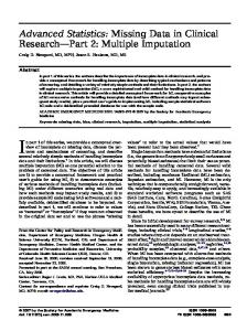
Figure la. Reflection arrival time versus shot location corresponding to rays propagating in the model presented in Figure 2. The receiver location is 5 km.
p; ttPg,p)(m) is thereflection arrivaltimealongthisraypath.
inverse problem and, finally, some results obtained with this
Provided that adequate conventions are used to define the signature of the reflected rays, it can be checked that (2) defines indeed a parametric representation of the reflection
method.
arrival
A New Formulation
of Travel
Time
Inversion
re
time curve.
2. We can use the same idea to describe the actual (or picked) reflection arrival time curve. The important point to
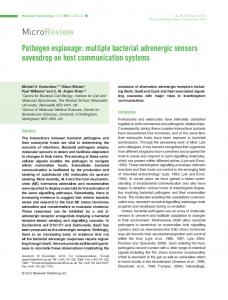
understand (see Appendix A) is that seismic data give, for some values taken by pairs (g, p) ranging within a set q3 describing our measurement points, an estimate of the emergence point (i.e., the shot location) of the ray (which has propagated in an unknown medium !) that leaves receiver functions v(x, z) andZ(x) areassumed tobeC 1continuous. location g according to ray parameter p and an estimate of Such models present attractive advantages regarding the the associated reflection arrival time. In other words, we continuity and the differentiability of kinematic events (both have discrete observations, corresponding to pairs (g, p) for the classical and the new formulation for travel time taking values ranging within the set q3, of the parametric inversion) and Versteeg [1991] has proved that they are also representation of the actual reflection arrival time curve: adequate for complex structure imaging. ( g, p) -->(s(g,p), act t(g,p)). . act , Let us consider an arbitrary model m and one shot, S, (4) located at s. Existence of multiple arrivals (i.e., the function To illustrate this, consider the reflection arrival time r(s, g) is multivalued) suggests"unfolding" the travel time curves presented in Figures la and lb that correspond to curve so as to have a single valued map. This can be achieved through a parametric representation of this curve. Of course, there are a lot (in fact, an infinity) of parametric representations of a given curve. This leads us to the four Receiver location (km) following questions: 3.0 4.0 5.0 I I I I 1. Which parametric representation do we choosefor the We will consider smooth models: velocity and velocity gradient discontinuities are not allowed even on the reflector. In other words, the model is defined by the velocity distribution v(x, z) and the reflector depth Z(x), where
predicted reflection arrivaltimecurver•)(m)?
1.8-
Which parametric representation do we choosefor the 9 pickedreflectionarrivaltimecurve•.pick ts,g). 3. We want to fit the predicted arrival time curve on the picked one. How should we pair points on picked and predicted reflection arrival time curves? 4. Given the way of pairing points on picked and predicted arrival time curves, which measure of the distance between points should we choose to measure the mismatch between predicted and measured data? We now propose an answer to these questionsand this will
ßßßß ßßßß ß ß ß ß ßßß ßß ßß
2.
lead to a new formulation
of travel
time inversion
that can
1.9-
ß ß ß ß ß
ß
2.0-
ßßßßß
E ,,,.,
ß
>
2.1-
ß
ß ß
ß
ooøø 00'
2.2!
2.3 -
!
cope with multiple arrivals. 1. The parametric representation chosen for the predicted reflection
arrival time curve is based on the fact that
shootingrays from a given point with a given initial direction defined by angle 0 allows to predict the emergencepoint and
Figure lb. Reflection arrival time versus receiver location correspondingto rays propagating in the model presented in Figure 2. The shot location is 5 km.
DELPRAT-JANNAUD
AND LAILLY:
REFLECTION
TOMOGRAPHY
705
Horizontal distance (km)
I
2
3
4
-•5•
6
7
00. .•. • • • ,•....... , ß•
•.i.!:i:!:i:!: ........................ :..•: •:.....• ß: .....i:i:•.i.i.i.:.:.:.:.:.:.:.:.:.:.:.:.:.:.:.:.:.:.:...:. :.:::::::::::::::::::::::::::::::::::::::::::::::::::::::::::::::::::::::::: •F..:i :'."
8
9
10
Velocity
m • I (km/s)
''•.:P•••;:• ?•);.::i•:i:•:i:::•.....::::•::::::::::::::i:!:;:i:;:i:i:!:i:!:i:i:i:;:i:•:i:•:i:•:!:i:iiii! •.•4•5 .................. .........................
•
2.4
Figure 2. Velocity field and reflector geometryused to computethe data presentedin Figure 1. The velocity field presentsa anomalouslyhigh positive velocity, and the reflector is syncline like. These two features of the model contribute to generate multiple arrivals.
rays propagatingin the model presented in Figure 2. If we have at our disposalreflection arrival times correspondingto neighboringreceivers (see the acquisition pattern presented in Figure 3), in the common shot sectionswe can read the ray parametersat the receivers and obtain two new sets of observations: the actual shot locations versus ray parameter values (Figure 4a) and the actual reflection arrival times versus ray parameter values (Figure 4b). Note that this is nothing but another representation of the usual reflection arrival time information! We just have to reorganize the data by a plain preprocessing.Note that a similar representation of arrival time data has already been used by Sword [1987] for reflection tomography and May and Covey [1981] for migration. 3. The problem now is to select the points on the actual and predicted reflection arrival time curves that should be compared with each other. We have chosen to compare points on these curves associatedwith the same value of the pair (g, p). More precisely, to evaluate how close a model m is to the actual Earth model, we evaluate, by shooting rays leaving receiver location g accordingto the value p of the ray
parameterat the receiver, how closethe predicted and actual shot locations are and how close the predicted and actual arrival times are, and this for all pairs (g, p) in •. In other
words, wein evaluate how close points (s•)(.tm), t•,•)(m)) calculated model maretoactual points is•,e),t(a•,t•)), for all pairs (g, p) in •. To ensure the comparison between predicted and actual
points to be always possible,we have to consider models that satisfy the set of inequality constraints
[p x
0)[ _:•:•:;:•:::=:•*!•*•=:=:•:•>•::;i:•:::•:•:•=:•::•::•:•>:• ..... ?•-..'•..•'..'g,g ........... :.-.:.:.;.:'.. I ::::::::•:::•:::::::::::::•::•:•=•=•:•;:;•;•;:;•;:•:;:•;:;:::::=•:;•:::==;;;•*•m•` , .:.:,::;.:=•:•:: ....... :::::•?::::::::::::::::::::•:::::::::::•::•::*::::::::::::::::::::::::::::::::::::::::::::::=;::::::::::::: ..... • •....:....:.:.:....m.:.=.=...-.:.:.:.=.:.:.•....:.:.:.:.;....:.:.=.:.:o:.=....:.•.:.:.:.:
•:•:•:•:•:•:•:•:•x.:•:...•:.:.:•:•:.:•:*..:•:::.:•:::::...i;....•.•+:.:•.:•:*..•`• •..:• • :... '*-, '............ •..::•::•:::::::::::::::::•:::.q:•:s•..s:..x:::.`•:•:.`.•:•:•`:•:..•..•.•.. ================================= o ......................................... .................................. ............ ..................... ....................................... .. ...... ............................................. == .... .................................. :::::::::::::::::::::::::::::::::::::::::::::::::::: t•_ d" .',•.,' ;'..•.•; •.'""-'o:s.•.-.'•,,..•. :.:.:.:.:....:.:.:o:.:.:.:.:.:....:.:.:.:.:.:.:...:.::v.:•:::• •.:.:....:.:.:.:... .• • .... ....•••••••••••••v•••••:•••v•••v•••••:•••:•••••••••••••••••••••••••:•••••••••••••••••••.•••••••.v•••:•:.•.••••••••••v:••••• ..., :.:ß , ,..,.:_..:•_::.::e...........................v.v...............v...v...
Figure 12. Solutionobtainedby invertingthe noisecorrupteddata in Figures 1l a and 1lb. Only the parts of the reflector illuminated by the rays are presented.
compute the covariance matrix are the same.) For the inversion, we use the same discretization intervals as the ones of the actual model. We start the inversion processwith the initial model presented previously (Figure 7). The value of the cost function for this initial model is 4 x 10⁷. The solution model (Figure 12) is obtained after 15 GaussNewton iterations. This model corresponds to a cost function equal to 900. (The value of the cost function for the actual model is 920.) The calculated travel time data are close to the reference ones (Figures 13a and 13b), which is satisfactory. The regularity imposed to the model essentially through the choice of the discretization intervals prevents the solution to match the noise. The predicted velocity field (Figure 12) is close to the actual one. In particular the velocity anomaly is well retrieved. The reflector depth (Figure 12) is retrieved with a high accuracy too. This model does not exhibit the well-known velocity-depth ambiguity since we use the same discretization
intervals
as in the actual
model. For details about the influence of the discretization, the reader can refer to Delprat-Jannaud and Lailly [1993].
In practice,the variances(/it2) and (/ip2) have to be
picking of the reflection arrival time curves and the estimation of their slopes.However, other tests made with different
butstillrealisticvaluesof (/it2) and(/ip2) for thecalculation of the covariance matrix (13) show the relative insensitivity of the solution of the inverse problem in the estimated variances.
Conclusions
Application of reflection tomography for the determination of complex geologic structures calls for a generalization of this method so that it can take triplications and other multiple arrivals into account. Such a generalization should allow the comparison between models that generate several or different numbers of reflection arrival times for one pair source-receiver.
To solve this problem, we propose a method that relies on an evaluation of the ray parameter at the receiver, a quantity
whichis obtainedby evaluatingthe slopeof the picked reflections in common shot gathers. A reorganization of reflection
arrival time data thus leads to the formulation
of a
estimated by guessingthe confidence we can have in the Ray parameter at the receiver (km/s)
Ray parameter at the receiver (km/s) -0.05
0.0
0.05
0.1
0.15
-0.05 I
1.8
0.0 I
0.05 I
0.1 I
0.15 I
m
1.9 '
E 2.0-
2.1-
2.2 -
Figure 13a. Shot location versus ray parameter at the receiver for noise-corrupted data (dots), reference data (pluses), and predicted data (crosses) associated with the solution model in Figure 12. The probability of each point to be in the bars (in grey) is larger than half of the maximum of the density function. The receiver location is 5 km.
Figure 13b. Reflection arrival time versus ray parameter for noise-corrupteddata (dots), reference data (pluses), and predicted data (crosses)associatedwith the solution model in Figure 12. The probability of each point to be in the bars
(in grey)is largerthanhalf of the maximumof the density function.
The receiver
location
is 5 kin.
712
DELPRAT-JANNAUD
AND
LAILLY:
REFLECTION
TOMOGRAPHY
new inverse problem. However, evaluation of the ray parameter at the receiver cannot be achieved with great accuracy. Therefore an adequate measure of the discrepancy between predicted and actual data has to be designed.More precisely, it is essential that this measure takes into account the sensitivity of data in an error in the measured ray
shot location
parameters.
An original algorithm has been proposed for the solution. In particular, the two-point ray-tracing problem, which may be tremendously difficult, is avoided. Moreover, the use of the adjoint state technique to compute the Jacobianoperator makes this solution cheaper than classicalreflection tomography. The effectiveness of this approach and the stability of the solution have been illustrated on a synthetic example with noise corrupted data.
Appendix A: Observed Ray Parameter Again, shots and receivers are assumed to be located at the surface. Let s and # denote the abscissae of shot S and receiver G, respectively, and let r(s, #) be the reflection arrival time for a ray propagating from S to G, or, equivalently, propagating from G to S. We denote by 0 the angle (measured with respect to vertical axis) of this ray at the receiver. The ray parameter p at the receiver # is (Figure 14)
p = sin O/v(#, 0).
(19)
Equation (19) shows that p can be interpreted as the horizontal projection of the slowness vector at G. In other
•1(s,g) Figure 15. The ray parameter at the receiver is the slopeof the reflection
arrival
shot sections.
with all pairs (s, #) yields a set denoted q3of pairs (#, p) describing the points in the (#, p) plane where we have measurements.Transposing (20), we can reorganize reflecact ) and • act tionarrivaltimedataandwe thusobtaindatas(a,p
which are formally defined by
p = Or(s•;t,.),g)/Og,
words, _ pick /
p = 0.,(s,g),0#.
(20)
geometry is essential at this stage to ensure the differentiability of the reflection arrival time function in (20).) Here p is thus the slope of the reflection arrival time curves in common shot sections (Figure 1:5). The ray parameter at the receiver can thus be readily obtained from the picked arrival
time data. This observation
characterizes
tact
(22)
Appendix B: Difficulties Involved in the Minimization of the Objective Function on a Difficult Example
sin 0
v(g,O)
m and
same branch toevaluate 0r•,•i,c•/0g.) Repeated use of (20) for all the arrival times associated
pre
g
Figure 14.
(•/,p)'• •'(saCt ,•/). (
In this appendix, we analyze the difficulties involved in the minimization of the objective functions (6) and (17) for recovering the model in Figure 2. The velocity field is described by 36 B spline functions (6 in x direction and 6 in z direction) and the reflector is describedby 20 B spline functions. We consider the velocity perturbation (which corresponds to a perturbation of the fifteenth velocity parameter) presented in Figure 16. This velocity perturbation is smooth and its maximum amplitude is smaller than 40 m/s. (It correspondsto a perturbation of 0.01 of the fifteenth velocity parameter. If it is added to actual model, the perturbed velocity model is very close to the actual one. However, it turns out that whereas most of the rays give rise to perturbations smaller than 10 m for the emergencepoint location and 1 ms for the reflection arrival time, some rays, hereafter referred to as pathological, give rise to perturbationsin emergencepoint location of some600
the final condition of the ray that leaves S and emerge at G. The ray parameter at G of the ray that leaves G to reach $ after propagation in the unknown actual Earth is thus -p. (Of course, in case of multiple arrivals, we must follow the
Ray parameter p _
(21)
and
(The C 1 assumption for the velocityfieldandthe reflector
reflection
time curves in common
x(g,p)(m)
Definition of the ray parameter at the receiver.
in reflection
arrival
times
of
some
60 ms.
The
contribution of such rays in the Hessian of the objective function (6) that we want to minimize is a large value for the corresponding velocity parameter. This leads to a large condition number. This argues against the use of objective function (6). The practical consequenceis that it is impossi-
DELPRAT-JANNAUD
AND
LAILLY:
REFLECTION
TOMOGRAPHY
713
Horizontal distance (km)
0 I 2 ,,3 4
, , -o o4
Figure 16. Velocity perturbation generated by a fifteenth parameter perturbation of 0.01.
ble to minimize (6) so as to retrieve the model in Figure 2 even with the help of a regularization. In (17) the discrepancy between actual and predicted data is minimized according to the confidence we have in the data. The consequence of such a formulation is that the effect of such pathological rays in the objective function is decreased when compared to other rays. Namely, the largest
where x(o-; m), z(o'; m), px(o'; m), and pz(O'; m) are the coordinates of the point of the ray associatedwith parameter o-, and the components of the slownessvector at this point, respectively. If the ray is parameterized by o-such that drr = dl/u
(24)
where I is the arc length along the ray, vector y satisfiesthe
diagonal termof the Hessianwhichwas 1013for the objecsystem of differential equations that defines the ray path tive functiondefinedin (6) falls to 107 for the objective (see, for instance Farra et al. [1989], or Jannaud [1992])
function defined in (17) when the variances on reflection arrival times and ray parameters at the receiver are 10 ms and 1%, respectively. Consequently, the linear systems involved in (17) are better conditioned and the minimization of (17) becomes possible.
/x(o';m)!
t(o'; m)
m), o-; m)
px(er; m)
=
• Ox(x(rr, m),z(rr,m))
(25)
10u 2
• • (x(o-; m),z(o';m)) u2(x(o';m), z(o'; m)) for any 0 -< rr -< rr•, with initial conditions (for rr = 0)
0
y(0; m)=
p
(26)
pz(0; m) 0
withpz(0;m) = (u2(g,0) - p2)1/2. We use as to denote the parameter correspondingto the emergence point at the surface. At this point, we have the following relations: pre
,
x(•rs; m)=s(a,p)tm)
(27)
Z(as; m) = 0
z(rr; m)
pz(rr; m)
(o'; m)=f(y(o';
10u 2
For the sake of simplicity, we will consider the continuum problem, where neither the model (velocity field and reflector depth) nor the ray path are discretized. Moreover, we will only consider a transmission problem (no reflection is involved). The solution of the reflection problem involves very technical calculations which are explained by B•cache [1992]. In this appendix we present the computation of the Jacobian of the correspondingcontinuum forward modeling operator. However, in practice, where the forward modeling is performed by a numerical procedure, we have to evaluate exactly the Jacobian of this numerical procedure as described by B•cache [ 1992]. This has been implemented but is not presented here for the sake of simplicity. Actually, we have two Jacobian operators to calculate, one associatedwith the predicted shot location and the other one associatedwith the predicted arrival time. We start with the calculation of the first Jacobian. Consider one ray, emitted by a shot point located at the surface in g with ray parameter p in model rn (the slownessof which is denoted by u(x, z)). Let •r denote the parameterization of the ray. A point on the ray is characterized by the column vector
px(er; m)
Orr
pz(rr; m)
Appendix C' Computation of the Jacobian Operators by the Adjoint State Technique
y(o'; m)=
oy
(23)
Let us now consider a model perturbation &n. This perturbation generates a perturbation of the point of the ray correspondingto parameter •rs, which is denoted by tSx(•rs; rn) and tSz(•rs;rn). Note that there is no reasonfor tSz(•rs;rn) to be zero. We use •rs + &r s to denote the parameter
714
DELPRAT-JANNAUD
AND
LAILLY:
associatedwith the point where the perturbedray emerges. From (25) we simply derive that &r s is definedby
REFLECTION
+
TOMOGRAPHY
Q*(o.; rn
where Q(o'; m), called the adjoint state, is defined as solution of the following linear differential equations
and consequently, /5o's = -
15z(o's; m) . Pz(o's; m)
(29)
Consequently, the perturbation of the emergence point of the ray, 15Xs,results from the contribution of two terms: the perturbationof the ray path generatedby the model perturbation, /Sx(o's;m), and the perturbation generated by the additionalray segmentwith length/5o's,
15Xs(o's; m)= 15x(o's;m)-
Px(o.s; m)
Pz(o.s;m)
oQ(o';m) of* + (y, o'; m)Q(o'; m)= O, Oo' Oy
backward in o' starting from final condition (32)). This definition leads to the following expressionfor the computation of the Jacobian
15Xs(o's; m)= Q*(O; m)/Jy(O; m)
15z(o.s;m).
+
m)of •0 •sQ*(o';
This relation can be simply written
15Xs(o's;m)= Q*(o's; m)lJy(o's; m)
(31)
where superscriptasterisk denotestranspositionand 1
.
(37)
u2(o.s;m)
(32) Q(o.s; m)=
0 0
OlJy Of =(y(o'; m), o'; m)/Jy(o'; m) Oy
(y(o'; m), o'; m)lJm.
0
.
(38)
0
We could calculate 15y(o's;m) by use of perturbed (or paraxial) ray equations
Om
do'.
0
m) -
0
Om
The computation of the Jacobian of the reflection arrival time is analogousto the previous calculation. We are thus led to define an other adjoint that satisfies propagation equations(35). Only the final condition of this adjoint state is modified: (32) becomes
Px(o's; m)
Q(o's; m)=
(36)
for any 0 -< o' -< o'swith the final condition(32) at o' =o's (and thus the integration of these differential equations is
(30)
+
(35)
(28)
Pz(o.s;m)15o.s =-15z(o.s; m),
Oo'
(y, o.; m)lJm do',
1
To conclude, we emphasize that each of the two components of the Jacobianis straightforwardly obtained by solving the adjoint equations(36), which is very cheapcompared to the more natural but tremendously expensive solution of equation (33).
(33)
Such an approachwould be extremely expensive:we would have to solve as many times (33) as there are possible perturbations/Sm, namely, an infinity for the continuum problem and a large number for a discretizedproblem. To calculate 15y(o' s; m), we will preferably use the adjoint state technique described hereafter. We start with
Acknowledgments. This research was carried out as part of the Pre-stack Structural Interpretation Consortium Project (PSI). The authors hereby acknowledgethe support provided by the sponsors of this project. The ray tracer was developed by Lionel Jannaud. The authors thank him for his precious help and his invaluable advices. The authors also thank Eliane B6cache, who has carried out the tedious calculations yielding the Jacobian of the discrete operator associated with the reflection problem.
Q*(o.s; rn)lJy(o.s;m)= Q*(O; m)/Jy(O; m) References
+
m))do', •s•0(Q)*(o';m)/Jy(o';
(34)
in which appears/Sy(0;m) that can be easilycomputedfrom (26). From the perturbed ray equations(33), we now derive
• [Q*(o'; m)/Jy(o'; m)] do' = • Ocr
B6cache,l•., Reflectiontomography: how to copewith multiple arrivals?, II, A new gradient computation method. Continuous and discrete problems: PSI Annual Report 1992, Inst. Ft. du P6trole, Rueil-Malmaison, France, 1992. Bishop, T. N., K. P. Bube, R. T. Cutler, R. T. Langan, P. L. Love, J. R. Resnick, R. T. Shuey, D. A. Spindiet, and H. W. Wyld, Tomographic determination of velocity and depth in laterally varying media, Geophysics, 50, 903-923, 1985. Delprat-Jannaud, F., and P. Lailly, Ill-posed and well-posed formulations of the reflection tomography problem, J. Geophys. Res., 98, 6589-6605, 1992.
+Q*(o.; m)0• (y, o.; m))/Jy(o.; m)do'
Delprat-Jannaud, F., and P. Lailly, Tomography with multiple arrivals: How to handlenoise corrupted data?, PSI Annual Report 1993, Inst. Ft. du P6trole, Rueil-Malmaison, France, 1993.
DELPRAT-JANNAUD
AND
LAILLY:
Farra, V., J. Virieux, and R. Madariaga, Ray perturbationtheory for interfaces, Geophysics, 99, 377-390, 1989. Fawcett, J. A., I, Three dimensionalray tracing and ray inversion in layered media; II, Inverse scatteringand curved ray tomography with applications, Ph.D. thesis, Calif. Inst. of Technol., Pasadena, 1983.
REFLECTION
TOMOGRAPHY
715
Sword, C. H., Tomographic determination of interval velocities from reflection
seismic data: The method of controlled
directional
reception, Ph.D. thesis, Stanford Univ., Stanford, Calif., 1987. Versteeg, R., Analyse de la d6termination du mod/•le de vitesse pour
l'imageriesismique(in English),th/•sede doctorat,Univ. de Paris VII, Paris, 1991.
Gray, S. H., EfiScienttraveltime for Kirchhoff migration, Geophysics, 51, 1685-1688, 1986. Jannaud, L., Two-point ray tracing in complex media: PSI Annual Report 1992, Inst. Fr. du P6trole, Rueil-Malmaison, France, 1992. Lee, E. B., and L. Markus, Fundations of optimal control theory, John Wiley, New York, 1967. May, B. T., and J. D. Covey, An inverse ray method for computing geologic structures for seismicreflections. Zero-offset case, Geophysics, 46, 268-287, 1981.
F. Delprat-Jannaud and P. Lailly, PSI Research Consortium, Institut Francais du P6trole, B.P. 311, 92506 Rueil-Malmaison C6dex, France.
(Received March 4, 1994; revised July 27, 1994; accepted September 14, 1994.)