Mobil Upstream Research Company, INCO Exploration, Information. Systems Laboratories, MTEM, Newmont Mining Co., Norsk Hydro,. OHM, Petrobras, Rio ...
Regularized integral equation based inversion of tensor induction logging data in three-dimensional formations Alexander Gribenko∗ and Michael S. Zhdanov, University of Utah SUMMARY There is growing interest in developing a three-dimensional (3-D) inversion and imaging technique from a single borehole. This problem can be solved by using tensor (multi-component) induction welllogging – TIWL. This method was originally introduced to resolve formation anisotropy. However, it was demonstrated in several publications that the TIWL instrument has sensitivity to 3-D conductivity distribution in the borehole vicinity. In previous works we introduced a method of fast 3-D imaging from a single borehole based on the localized quasi-linear (LQL) approximation. In the current paper we introduce a combined method of iterative LQL inversion of the TIWL data and rigorous integral equation (IE)-based inversion. Addition of the rigorous inversion stage improves the LQL inversion result significantly, and provides more accurate inversion error estimation. A new algorithm of 3-D TIWL data interpretation is tested for several models of typical 3-D structures located in the vicinity of the borehole.
INTRODUCTION There is growing interest in developing an inversion and imaging technique from a single borehole. Technically, this problem can be solved by using tensor (multi-component) induction well-logging – TIWL (Kriegshauser et al., 2000; 2001). It was demonstrated in several publications that the TIWL instrument can be used both for studying the resistivity anisotropy and for imaging 3-D structures in the borehole vicinity (Zhdanov et al., 2001; 2004; Wang et al., 2003; Abubakar et al., 2006 ). In the current paper we are focusing on the problem of 3-D inversion of the array TIWL data. It was shown by Portniaguine and Zhdanov (1999), Alumbaugh and Wilt (2001), Cheryauka et al. (2001), and in several other publications that the TIWL data can be used to study the 3-D conductivity structure in the borehole vicinity. A method of fast 3-D imaging from a single borehole based on the localized quasilinear (LQL) approximation was presented by Zhdanov et al. (2004). We now consider a combined method of iterative LQL inversion of the TIWL data and rigorous integral equation (IE)-based inversion. A new algorithm of 3-D TIWL data interpretation is tested for several models of typical 3-D structures located in the vicinity of the borehole. One of the synthetic models considered in this paper is similar to the oil-water contact model presented by Abubakar and Habashi (2006).
ITERATIVE INVERSION The main difficulties in the modeling and interpretation of induction logging data in 3-D inhomogeneous formations are related to the fact that, for any new observation point, one has to solve the forward problem anew for the corresponding position of the moving transmitter. In this situation, even forward modeling of the well-logging data over inhomogeneous structures requires an enormous number of computations. The inversion of the logging data becomes even more time consuming because it requires repeated forward modeling with the updated model parameters. This situation is very similar to the one we are dealing with in the case of airborne data interpretation with the moving transmitter-receiver pairs located on the helicopter or airplane. In order to overcome this difficulty, we apply to the inversion of the induction well-logging data a method based on the iterative LQL in-
version (Zhdanov and Tartaras, 2002; Zhdanov, 2002), followed by rigorous inversion. The LQL approximation is a powerful instrument for fast 3-D modeling and inversion of multi-source electromagnetic (EM) geophysical data. It has been successfully applied to the modeling and inversion of borehole EM data (Zhdanov et al., 2004). This approach can be used in borehole geophysics where fast 3-D imaging is required. In the current paper we extend this approach by applying the rigorous step of the iterative inversion. We consider a 3-D geoelectrical model of rock formations with background conductivity σb and local inhomogeneity D with arbitrary spatial variations of conductivity σ = σb + ∆σ . The background conductivity is formed by a layered formation which may consist of an arbitrary number of homogeneous layers with different conductivities and thicknesses. A tensor induction logging instrument detects three components of the total magnetic field due to each of three transmitters (Zhdanov et al., 2001). Our goal is to find the anomalous conductivity from the given measurements of the anomalous magnetic field by the moving tri-axial induction instrument. The integral equation (IE) numerical modeling method allows us to express the anomalous magnetic and electric fields, Ha and Ea , due to a 3-D anomalous zone located outside a borehole in a layered background, as the integrals of a product of the anomalous conductivity and the total electric field over the anomalous domain, D (Zhdanov, 2002): h ³ ´i ¡ ¢ HaI r j = GH ∆σ EbI + EaI ,
(1)
´i h ³ ¡ ¢ EaI r j = GE ∆σ EbI + EaI ,
(2)
where GH and GE are the magnetic and electric Green’s linear operators for a background model. Note that the observed magnetic field depends on the illuminating transmitter and the corresponding background field EbI (r), where I = 1, 2, ...N is the index of the transmitters. Equation (1), which connects the observed magnetic field at the receivers with the electric field inside the anomalous domain, D, represents a field equation. Writing equation (2) for the points within the anomalous domain, r j ∈ D, we arrive at a domain equation. In the framework of the LQL approximation, we assume that the anomalous electric field inside the anomalous domain is linearly proportional to the background electric field through an electrical reflectivity tensor b λ: EaI (r) = b λ (r) · EbI (r) , I = 1, 2, ...N, (3) which is assumed to be source independent. Using the LQL approximation, we can obtain one linear inverse problem for the entire observation array. Further details of solving the inverse problem and finding the anomalous conductivity can be found in Zhdanov (2002) and Zhdanov et al. (2004). We will denote the anomalous conductivity obtained by the LQL inversion as ∆σLQL . We have demonstrated in the previous publications (Zhdanov et al., 2004) that in many practical situations this conductivity delivers a correct image of the true geoelectrical structures surrounding the borehole. However, one can treat the LQL-generated conductivity as an initial model of the appropriate iterative inversion. In the current paper we have extended this method to solve the field equations within the modeling domain rigorously.
Regularized 3-D inversion of array tensor induction logging data After LQL inversion, we formulate IE for the electric field within the modeling domain using the anomalous conductivity ∆σLQL found durpr(0) ¡ ¢ r j denote the predicted anomalous ing LQL inversion. Let HI magnetic fields in the receivers computed for the conductivity model ∆σLQL using IE formulas. We can estimate now how accurate our LQL inversion is by computing the normalized error of the LQL approximation, εLQL : ° ¡ ¢° ° pr(LQL) ¡ ¢ ° r j − HaI r j ° °HI ° a ¡ ¢° εLQL = , (4) °H r j ° I ¡ ¢ where HaI r j is a corresponding observed anomalous magnetic field. We finish the inverse process if the error of the LQL inversion εLQL is less than the given accuracy level ε . Otherwise, we can apply the inversion iteratively.
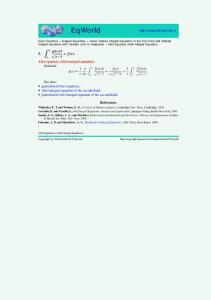
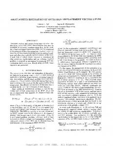
NUMERICAL EXAMPLE: AN OIL-WATER CONTACT MODEL As a modeling example we present the model similar to the oil-water contact model considered by Abubakar and Habashy (2006). We use a homogeneous half-space with 0.05 S/m conductivity as a background for this model. The formation consists of a deviated water layer with conductivity of 0.1 S/m and a water-oil contact region. The conductivity of the oil is 0.01 S/m and of the water it is 0.1 S/m. Figure 1 represents a vertical section through the anomalous conductivity distribution in the true the oil-water contact model, and Figure 2 is a 3-D view of the same model.
The rigorous stage of the inversion algorithm is based on the iterative solution of the field and domain equations (1) and (2). Determining accurate predicted data once the electric field is known is a straightforward process requiring only matrix multiplication. Rapidly calculating the true domain electric field is more challenging. We use the updated (0) field EI (r) to find an updated conductivity ∆σ (1) (r) from the field equation (1), relating the anomalous conductivity and the observed magnetic data: h i ¡ ¢ (0) (5) HaI r j = GH ∆σ EI , I = 1, 2, ...N. Note that inverse problem (5) is an ill-posed problem. The solution of this problem requires application of the corresponding regularization methods (Tikhonov and Arsenin, 1977, Zhdanov, 2002). The traditional inversion algorithms are based on the smooth regularization, which has difficulties, however, in describing the sharp geoelectrical boundaries between different geological formations, e.g., in inversion for a local resistive or conductive target with sharp boundaries between the resistor/conductor and the host rocks. In our rigorous inversion algorithm we use focusing regularization based on a special type of focusing stabilizing functionals, the so-called minimum support or minimum gradient support functionals (Portniaguine and Zhdanov, 1999, Zhdanov, 2002). We solve inverse problem (5) using the re-weighted regularized conjugate gradient (RRCG) minimization in logarithmic model parameter space, which can incorporate both the smooth regularized inversion, generating a smooth image of the inverted resistivity, and a focusing regularized inversion, producing a sharp focused image of the geoelectrical target.
Figure 1: A vertical section through the anomalous conductivity distribution of the oil-water contact model.
In the next step, we can employ the updated conductivity ∆σ (1) for updating electric field E(1) (r) , using the corresponding domain equation (2) for the electric field: h i ¡ ¢ (1) ¡ ¢ (1) EI r0 = GE ∆σ (1) (r) EI (r) + EbI r0 , I = 1, 2, ...N. (6) (1)
Again, we rigorously solve equations (6) for EI (r) using the contraction operator method (Hurs´an and Zhdanov, 2002). For the model with the conductivity ∆σ (1) (r) , we can calculate the predicted anomalous pr(1) ¡ ¢ magnetic field HI r j based on the equation: i h (1) pr(1) ¡ ¢ (7) HI r j = GH ∆σ (1) EI .
Figure 2: 3-D view of the anomalous conductivity distribution of the true oil-water contact model.
In step (k), we find an updated conductivity ∆σ (k) (r) and updated field pr(k) HI . The accuracy of this solution is estimated by an error: ° ¡ ¢° ° pr(k) ¡ ¢ ° r j − HaI r j ° °HI ° a ¡ ¢° εk = . (8) °H r j °
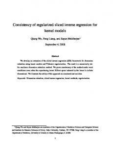
The TIWL data are collected along a vertical borehole. The transmitter locations are shown in Figures 1 and 2 by stars. The TIWL instrument is formed by a set of three mutually orthogonal receivers and six sets of three receivers located at 38, 53, 68, 100, 137, and 183 cm away from the transmitter. The operating frequency is 20 kHz. The synthetic observed data are computed by the IE method with MGQL approximation (Ueda and Zhdanov, 2006). The observed data are contaminated by 5% random noise. An example of the observed and predicted data plots is shown in Figure 3 for component Hxz .
I
The iterative inversion process continues until we reach the required level of the misfit.
We used a 4 × 4 × 10m3 inversion domain surrounding the borehole. It
Regularized 3-D inversion of array tensor induction logging data
Figure 3: The real and imaginary parts of the Hxz component recorded by the TIWL instrument for the oil-water contact model.
Figure 5: A vertical section of the anomalous conductivity distribution for the oil-water contact model obtained by LQL inversion.
was discretized into 10,240 cubic cells with a side of 0.25 m. First we ran 10 iterations of the LQL inversion, and then the rigorous stage of the iterative inversion. The iterative inversion with a rigorous update consists of three electric field updates with 10 inversion iterations after each update. The convergence plot is shown in Figure 4. One can see that, after updating the electric field the LQL inversion error reaches almost 70%. The vertical cross-section of the anomalous conductivity distribution obtained by the LQL inversion is shown in Figure 5. Figure 6 represents a vertical cross-section of the final model obtained after the rigorous stage of the inversion. A 3-D view of the same rigorous inversion result can be found in Figure 7. One can see that these images represent well the original model, and using the rigorous stage of inversion improves the result compared to the LQL inversion. The inversion took approximately four hours on a dual-core dual Opteron 2.0 GHz (4 CPUs total) Linux PC.
Figure 6: A vertical section of the anomalous conductivity distribution for the oil-water contact model obtained after rigorous iterative inversion.
Figure 4: Plot of the normalized errors versus iteration number for the the oil-water contact model inversion.
CONCLUSION In this paper we developed a new technique for rigorous 3-D inversion of TIWL data from a single borehole. We have extended the original LQL method for the solution of a full 3-D inverse problem. Our extension is based on adding a rigorous stage of inversion with the appropriate accuracy control of the inversion results. The new volumetric
Figure 7: A 3-D view of the anomalous conductivity distribution for the oil-water contact model obtained after rigorous inversion.
Regularized 3-D inversion of array tensor induction logging data nonparametric inversion method was carefully tested on a set of realistic 3-D geoelectrical models, typical for an HC reservoir study. The numerical modeling and inversion results have shown that the iterative regularized inversion can be effectively used for 3-D EM imaging from a single borehole.
AKNOWLEDGEMENTS The authors acknowledge the support of the University of Utah Consortium for Electromagnetic Modeling and Inversion (CEMI), which includes BAE Systems, Baker Atlas Logging Services, BGP China National Petroleum Corporation, BHP Billiton World Exploration Inc., Centre for Integrated Petroleum Research, EMGS, ENI S.p.A., ExxonMobil Upstream Research Company, INCO Exploration, Information Systems Laboratories, MTEM, Newmont Mining Co., Norsk Hydro, OHM, Petrobras, Rio Tinto - Kennecott, Rocksource, Schlumberger, Shell International Exploration and Production Inc., Statoil, Sumitomo Metal Mining Co., and Zonge Engineering and Research Organization. We thank Martin Cuma for his assistance with inversion computations.