690
IEEE TRANSACTIONS ON MAGNETICS, VOL. 44, NO. 6, JUNE 2008
Reinterpretation of the Nodal Force Method Within Discrete Geometric Approaches François Henrotte1 , Ruben Specogna2 , and Francesco Trevisan2 Institute of Electrical Machines, RWTH Aachen University, Aachen D-52056, Germany Dipartimento di Ingegneria Elettrica, Gestionale e Meccanica, Università di Udine, I-33100 Udine, Italy We propose a geometric reinterpretation of the Nodal Force Method in the framework of a pair of discrete formulations for magnetostatics on complementary meshes. Index Terms—Discrete approaches, forces, magnetostatics.
I. INTRODUCTION
T
HE FORCE distribution on a body can be computed by means of the so-called “Nodal Force Method” (NFM), proposed by [2]–[5] in the framework of finite elements. The aim of this paper is to provide a geometric reinterpretation of the NFM, when used within discrete geometric approaches [1], [7]. We will focus on magnetostatics, and we will consider a pair of discrete formulations1 on complementary meshes to solve the magnetostatic problem; one formulation takes the circulation of the vector potential as unknowns, whereas the other uses a scalar magnetic potential and the circulation of the electric vector potential, in the region of the source currents. In both cases, we will express the contribution to the resulting force acting on a node of a tetrahedron in terms of the geometric entities of the mesh and of the global electromagnetic quantities like the fluxes of the induction field or the circulations of the magnetic field. A numerical example is used to compare the resulting force acting on a body. We verify numerically that averaging the resulting force values computed from the pair of complementary formulations yields a good approximation of the actual resulting force even with a relatively poor mesh. This result holds also in the framework of finite elements [8]. II. DISCRETE FORMULATIONS FOR MAGNETOSTATICS consists of a source region , The domain of interest , where where known currents are present, and of a region and magnetic materials are present; the complement of in is the air region . We introduce in a pair of interlocked cell complexes [6], [7]. One complex is made of simplexes, i.e., nodes, edges, faces (triangles), and volumes (tetrahedra), while the other is obtained from it, according to the barycentric subdivision.
Digital Object Identifier 10.1109/TMAG.2007.916237 Color versions of one or more of the figures in this paper are available online at http://ieeexplore.ieee.org. 1These formulations are part of the Geometric Approach for Maxwell’s Equations (GAME) code developed by R. Specogna and F. Trevisan with the partial support of MIUR (Italian Ministery for University and Research).
Each geometric element of a cell complex is endowed with an orientation [7]. The cell complex whose geometric elements are endowed with inner orientation is referred to as the primal complex and denoted by , whereas we denote by the cell complex whose geometric elements are endowed with outer orientation. As the same geometric element of a complex can be thought with two complementary orientations, we may conand , struct two pairs of meshes where the superscript " indicates the simplicial complex. The geometric elements of the primal mesh ( for or for ) are denoted by for nodes, for edges, for faces and for volumes; whereas the geometric elements of the dual mesh or for ) are denoted by , , , respectively. ( for The interconnections between the geometric elements of a or are described by means of incidence complex of matrices. In particular for the simplicial primal complex , we the incidence matrix between and , by the denote by incidence matrix between and and by the incidence matrix between and ; similarly for the simplicial dual complex we write , and respectively. In particular between the and we have that , incidence matrices of , hold.2 Next, we consider the integrals of the field quantities, also referred to as integral variables, for a magnetostatic problem with respect to the oriented geometric elements of a mesh or , yielding the degrees of freedom (DoF) arrays (denoted in boldface type); each entry of a DoF array is indexed over the corresponding geometric element. There is a univocal association between a global variable and the corresponding geometric element [7], and we denote with the following: the array of magnetic induction fluxes associated with • primal faces in ; the array of magnetomotive forces (m.m.f.s) associated • with dual edges in ; • the array of electric currents associated with dual faces. Now, in order to compute the resulting force acting on a body, we have to first solve the magnetic problem by evaluating the fluxes on primal faces or the m.m.f.s along the dual edges of or [11]. The discrete formulations needed to a mesh or to compute with respect compute focusing on mesh are briefly recalled in the next two sections. to 2The minus sign comes from the assumption that inner/outer orientations of a node are opposite.
0018-9464/$25.00 © 2008 IEEE
HENROTTE et al.: REINTERPRETATION OF THE NODAL FORCE METHOD
691
A. Formulation in In we consider the mesh and we refer all the incidence . We search for a DoFmatrices to the simplicial complex array of the circulations of the magnetic vector potential such that along the primal edges of (1) hold, where (1a) is the Ampère’s Law at discrete level and is the array of currents crossing the dual faces of ; has only. The square nonnull entries for the dual faces of in matrix ( , being the number of faces in ) is the reluctance matrix such that (1b) holds exactly at least for an element-wise uniform induction field B and magnetic field H in each tetrahedron; it is the approximate discrete counterpart at contincorresponding to the constitutive relation uous level, being the reluctivity assumed element-wise a constant. The reluctance matrix can be computed according to the following approaches [10], [12], [15]. Finally, (1c) assures that is satisfied identically, Gauss’ Law at discrete level holds. since By substituting (1b) and (1c) in (1a), we obtain the final algebraic system
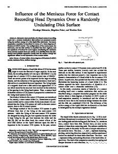
Fig. 1. (A) Tetrahedron v 2 L is shown, having two nodes on @D . (B) Pair n, f is shown for a tetrahedron v 2 L. Three edges drawn from node n are displayed; edge e and face f form a pair.
Then by substituting (3b) and (3c) in (3a), we obtain the final system of equations (4) where the boundary conditions must be specified in terms of on the dual nodes on the boundary of . III. NODAL FORCE METHOD
(2) for which the boundary conditions must be specified in terms of on the primal edges on the boundary of . B. Formulation in In we consider the mesh and we refer all the incidence . We search for a DoFmatrices to the simplicial complex array of magnetic scalar potentials associated with the dual such that nodes of
We indicate with a layer of tetrahedra enclosing the mag, such that and each tetrahedron netic domain (or ) may have up to 4 nodes on , Fig. 1(A); we denote by one of these nodes and with the set they form. assoThen, the contribution to the resulting magnetic force ciated with node of can be written in a general way as [2], [3], [5] (5) where
(3) hold, where (3a) is Gauss’ Law at discrete level and is the known array of the circulations of the electric vector potential along dual edges; it has nonnull entries for the dual edges of belonging to the region and to some of the edges region also referred to as thick cut region [17]. The of , where is the array satisfies the following property array having nonnull entries only for the currents crossing the . To compute the array dual faces in the source region from , the technique described in [9] can be used. The square , being the number of edges in ) matrix ( is the permeance matrix such that (3b) holds exactly at least for element-wise uniform H, B fields in each tetrahedron; it is the approximate discrete counterpart corresponding to the constiat continuous level, being the permetutive relation ability assumed element-wise a constant. The permeance matrix can be computed as described in [13] and [15]. Finally, (3c) asis identically sures that Ampere’s Law at discrete level holds. satisfied, since
is the Maxwell stress tensor in terms of , fields, is the magnetic energy density of the material and is the identity tensor. Finally is an arbitrary function (we need at least to compute the gradient of it) with support in ; it is 1 on and 0 on . In the following, we will consider linear holds. media only and Now, we will concentrate on the single tetrahedron (or ), since the resultant force acting on the body, is the sum of the contributions , with , from all . In one given tetrahedron, (or ), there is only one nodal shape function associated with a given node. The function can be expressed as the sum of the Whitney nodal function associated with (or ). Then, it is easy to show, (or in ), the gradient of [12], that, in the primal complex a Whitney nodal function can be written as (6)
692
IEEE TRANSACTIONS ON MAGNETICS, VOL. 44, NO. 6, JUNE 2008
where is the area vector whose magnitude equals the area opposite to node , Fig. 1(B) and that is perof the face and pointing in a way congruent (according to pendicular to the right-handed screw rule) with the orientation of that face. provided we swap The same relation holds in the complex with , respectively. Entry is the incithe pair , dence number between the orientations of and of . Similarly between and of the incidence is . Finally is the volume of the tetrahedron.
dron . Again, this solution in terms of magnetomotive forces is consistent, by construction, with an element-wise uniform H field, since the permeance matrix in (4) has been computed in order to comply exactly with this requirement. Thus, we can assume that the field H is uniform in . Then following a reasoning similar to the one used to deduce (8) but at a different geometric level, it can be shown that a uniform magnetic field H in such that , can be expressed as (12)
A. Geometric Reinterpretation Using the Formulation in From the formulation (2), we can compute the fluxes , with of the induction field on the four faces of , which comply with the Gauss’ law at discrete level (7) is the incidence number between the orientations where of and . This solution in terms of fluxes is consistent, by construction, with an element-wise uniform B field, since the reluctance matrix in (2) has been computed in order to comply exactly with this requirement. For this reason, we can assume that the B field is uniform in . Thus a possible way to deduce a uniform B in from the fluxes, can be obtained by generalizing what has been shown in [12], as (8) where , with , is the edge vector associated with edge drawn from node , Fig. 1(B), is the induction flux associated with face having node as a vertex; face pairs and are the incidence numbers bewith . Integers tween the orientations of , and , respectively. Next, by substituting (6) in (5), the contribution to the total becomes force with respect to mesh (9) and by substituting in it (8) for B and using (7) to express , after reordering, we obtain (10) where (11) It should be noted that the vector contains all the geometric information and medium parameters being a linear combination of the edge vector associated with the edge drawn from the common node and the face vector associated with the face opposite to . B. Geometric Reinterpretation Using the Formulation in The formulation (4) allows the computation of the m.m.f.s , with along the six dual edges of the tetrahe-
where , with , is the face vector associated with dual face having node as vertex, is the m.m.f. associated with the dual edge drawn from node ; also in this case the and dual face pairs with the dual edge . Integers are the incidence numbers between the inner orientations of the pairs , and , respectively. Next, by substituting (6) in (5), the contribution to the total can be written as force with respect to mesh (13) and by substituting (12) in it for H after reordering, we obtain (14) where
(15) Again the vector contains all the geometric information and medium parameters, being a linear combination of the face vector associated with the dual face having one vertex coincident with the node and the face vector associated with the dual face opposite to . IV. NUMERICAL EXPERIMENT AND RESULTS In order to validate and compare the pair of complementary formulation at the base of the force computation, we considered the problem of evaluating the resultant force acting on a placed in the vicinity of a magnetic cylinder and circular coil (400 turns, 1 A per turn) . The magnetic the source domains are surrounded by air. The geometry is axisymmetric and it is shown in Fig. 2. We solved this problem as a pure 3-D magnetostatic problem using the formulations and on a number of different complementary meshes and ; for brevity in Table I, we denoted such meshes with with and we reported the number of tetrahedra of the corresponding simplicial complexes. The systems (2) and (4) are singular, and to solve them we rely on CG method without gauge condition [18] with a SSOR preconditioner. The CPU times needed to solve the systems on a Pentium IV, 3-GHz, 2-GB RAM computer are also reported in the table. As a reference, we considered a 2-D axisymmetric
HENROTTE et al.: REINTERPRETATION OF THE NODAL FORCE METHOD
693
much lower than the corresponding error due to a single formulation for the same grain of the mesh. In Fig. 3 we compared the and toward convergence of the computed total forces , as the refinement of the mesh inthe reference value creases with ; the averaged value is shown in addition. V. CONCLUSION
Fig. 2. Geometry of the test problem where the magnetic D domains are shown.
and source D
TABLE I ERRORS AND CPU TIME FOR A AND FORMULATIONS
We presented a geometric reinterpretation of the nodal force computation method. It is based on the geometric treatment of the Maxwell’s stress tensor, and it holds exactly under the assumption of element-wise uniform fields within each tetrahedron of the mesh. This same assumption is also at the base of the computation of the consistent reluctance and permeance constitutive matrices of a pair of discrete geometric formulation and on a pair of complementary meshes respectively. The convergence of the computed total force toward a reference value is demonstrated numerically as the refinement of the mesh is increased. Moreover, we numerically verify that the error in the force computation can be reduced by averaging the force values computed from each of the formulations. REFERENCES [1] [2] [3] [4] [5] [6] [7] [8] [9] [10] [11] [12] [13]
Fig. 3. Convergence of the total forces as the refinement of the mesh is increased.
[14] [15] [16]
analysis with the ANSYS code, yielding a total force (along the direction) mN, using about 20 000 secondorder quadrilateral elements. The percentage errors , are reported in the fourth and fifth rows of Table I. As a numerical result, we verify that always hold, where is the actual error affecting the force value for a given coarseness of the mesh. In addition, we also verify that holds approximately. The averaged error is
[17] [18]
A. Bossavit, IEEE Trans. Magn., vol. 34, no. 5, pp. 2429–2432, 1998. A. Bossavit, IEEE Trans. Magn., vol. 28, no. 9, pp. 1263–1265, 1992. A. Kameari, Int. J. Appl. Electr. Mater., vol. 3, pp. 231–240, 1993. Z. Ren and A. Razek, IEEE Trans. Magn., vol. 28, no. 2, pp. 1212–1215, 1992. F. Henrotte, G. Deliége, and K. Hameyer, Int. J. Comput. Math. Electr. Electron. Eng., vol. 23, no. 4, pp. 996–1005, 2004. A. Bossavit and L. Kettunen, IEEE Trans. Magn., vol. 36, no. 4, pp. 861–867, 2000. E. Tonti, IEEE Trans. Magn., vol. 38, no. 2, pp. 333–336, 2002. J. Penman and B. Grieve, Proc. Inst. Elect. Eng., vol. 133, no. 4, pp. 212–216, 1986. Y. Le Menach, S. Clenet, and F. Piriou, IEEE Trans. Magn., vol. 34, no. 5, pp. 2509–2512, 1998. R. Specogna and F. Trevisan, IEEE Trans. Magn., vol. 41, no. 4, pp. 1259–1263, 2005. F. Henrotte and K. Hameyer, J. Comput. Appl. Math., no. 164, pp. 235–243, 2004. F. Trevisan and L. Kettunen, IEEE Trans. Magn., vol. 40, no. 2, pp. 361–365, 2004. F. Trevisan and L. Kettunen, Int. J. Numer. Meth. Eng., vol. 67, no. 13, pp. 1888–1908, 2006. T. Tarhasaari, L. Kettunen, and A. Bossavit, IEEE Trans. Magn., vol. 35, no. 3, pp. 1494–1497, 1999. L. Codecasa and F. Trevisan, Int. J. Numer. Meth. Eng., vol. 65, no. 4, pp. 548–565, 2006. L. Codecasa, R. Specogna, and F. Trevisan, IEEE Trans. Magn., vol. 42, no. 2, pp. 510–515, 2007. L. Kettunen, K. Forsman, and A. Bossavit, Int. J. Numer. Meth. Eng., vol. 41, no. 5, pp. 935–954, 1998. A. Kameari and K. Koganezawa, IEEE Trans. Magn., vol. 33, no. 2, pp. 1223–1226, 1997.
Manuscript received June 24, 2007. Corresponding author: F. Trevisan (e-mail:
[email protected]).