Relating Feature Models to Other Models of a Software Product Line A Comparative Study of FeatureMapper and VML* Florian Heidenreich1 , Pablo S´anchez2 , Jo˜ao Santos3 , Steffen Zschaler4 , Mauricio Alf´erez3 , Jo˜ao Ara´ujo3 , Lidia Fuentes5 , Uir´a Kulesza3 , Ana Moreira3 , and Awais Rashid4 1
Technische Universit¨at Dresden, Germany
[email protected] 2 Universidad de Cantabria, Santander, Spain
[email protected] 3 Universidade Nova de Lisboa, Portugal {mauricio.alferez|ja|amm}@di.fct.unl.pt, {jpgpsantos|uirakulesza}@gmail.com 4 Lancaster University, UK {zschaler|awais}@comp.lancs.ac.uk 5 University of Malaga, Spain
[email protected]
Abstract. Software product lines using feature models often require the relation between feature models in problem space and the models used to describe the details of the product line to be expressed explicitly. This is particularly important where automatic product derivation is required. Different approaches for modelling this mapping have been proposed in the literature. However a discussion of their relative benefits and drawbacks is currently missing. As a first step towards a better understanding of this field, this paper applies two of these approaches— FeatureMapper as a representative of declarative approaches and VML* as a representative of operational approaches—to the case study. We show in detail how the case study can be expressed using these approaches and discuss strengths and weaknesses of the two approaches with regard to the case study.
1
Introduction
A software product line (SPL)—such as the case study under discussion [1]—is a set of software-intensive systems sharing a common, managed set of features that satisfy the specific needs of a particular market segment or mission and that are developed from a common set of core assets in a prescribed way [2, 3]. Apart from sharing a common set of features, every system also has features that are specific to this system and not shared with other systems in the SPL. For the purposes of this paper, we are using the following definition of feature: “A prominent or distinctive user-visible aspect, quality, or characteristic of a software system or systems.” [4] as cited in [5]
An important part of managing the features of a product line and the individual systems (often called products) is to model the available features and their dependencies (e.g., if feature A is selected, feature B also must be selected) in an abstract form. In particular, it is essential to produce models for the variable features. Often, this is done using so-called feature models (e.g., [5]). The case study under discussion is an example of such a product line. In this paper, we focus solely on product lines modelled using feature models. While these models express what features there are and what products can be formed from them, they do not express how a specific feature is realised, and, thus, how any specific product is realised. Typically, there also need to be models that describe how the SPL is realised; that is, models of the solution space for the SPL. This is particularly relevant in a modeldriven setting, where product code is generated from product models. For instance, let us consider a simple SPL for a chess game for mobile phones, where the product can be delivered with three levels of expertise: beginner, medium and master. A feature model would only specify that there are three levels, and that the user must select one, but it does not specify how these alternatives are supported at the software level. This might be by means of different techniques, such as using a strategy pattern or conditional compilation, among others. Thus, we also need software models that specify which particular kind of technique we have selected for realising the variations at the softwaredesign level. In SPL terminology, feature models are said to be problem-space models, and software models, such as architectural design models, are said to be solution-space models. To automate product derivation, we also need to know what actions or manipulations should be applied to the software models as a certain feature is included or excluded in/from a specific product. For instance, if we have opted for using the strategy pattern for designing a set of alternative features, we need to know which strategies correspond to each feature. Since it is not always possible to establish a clear one-to-one mapping between features and model elements, this is not a trivial task. This leads to a mapping problem: For each feature in a feature model we need to identify and specify the solution-space models and model elements associated with it to be able to systematically construct products given a selection of features. In this paper, we will use the term variability mapping to refer to the activity of expressing explicitly the relationship between features and model elements. Note that this does not imply that the relation between features and their realisation must be ’discovered after the fact’. Variability will be designed into solution-space models because there is a corresponding variation point in the feature model. However, to enable automation of product derivation, this relationship (or mapping) must be made explicit in some form. Depending on how we choose to model the SPL’s architecture, this mapping may be very simple or very complex. For example, where aspect-oriented or feature-oriented techniques are used for the SPL models, we can attempt to align every feature with one module of these models. Using more standard object-oriented modelling techniques, some features will have to be mapped to a number of model elements across the entire SPL; that is, they will be cross-cutting features. Aspect-oriented modelling (AOM) is about the separation of different concerns in different (partial) models that can then be composed into a representation of the com-
plete system. Variability modelling fits well into this description: A key principle is to separate the model elements related to different features (’concerns’). This is done by either physically separating them in separate models or virtually separating them using different tags to associate model elements to features. A first step in product derivation is then the composition of these separate concerns into models of a complete product. Variability models address the mapping problem mentioned above to provide both separation of concerns and composition of the separated models into product models. A number of different approaches to variability mapping have been proposed [6– 11]. These proposals take different approaches to the mapping problem. Some approaches use a declarative model of the mapping between features and model elements (e.g., [6, 7, 9]) while others use a more operational approach based on model transformations (e.g., [8, 10, 11]). This paper applies two of these approaches—FeatureMapper [9] and VML* [11]—to the case study and discusses their respective advantages and drawbacks. FeatureMapper is a generic tool that can be used directly with any EMFbased model [12] and GMF, Ecore, or EMFText-based [13] editor. It directly relates features and model elements and derives product models by removing all model elements associated with features not selected for that product. In contrast, VML* uses languages customised for each target model. For instance, for target models of components and connectors, VML* can be customised to provide constructs in terms of components and connectors. It is still generic, because it is based on a customisable infrastructure that can be easily adapted for any new target model using a generativeprogramming approach. Each language consists of a set of actions corresponding to simple model transformations that are executed depending on the features selected for a product. The two approaches have been selected because they are good representatives of declarative and operational approaches, respectively. Therefore, we believe the results from a comparison of these two approaches can also provide some insights into the relative benefits and drawbacks of declarative and operational approaches to the mapping problem.6 Furthermore, each of the approaches has been developed by some of the co-authors of this paper. This gives us full access to the approaches and their accompanying tooling, which is key to an evaluation against the common case study. A more detailed discussion of the spectrum of different approaches and our selection can be found in Sect. 2.2. We have defined a set of comparison criteria to support a systematic comparison of the two approaches. These criteria have been defined to cover a broad spectrum of characteristics relevant when using a variability-modelling approach. In particular, they can be grouped into criteria on the expressiveness of the approach (i.e., what types of variability and what artefacts does the approach support), criteria on the useability and analysis support (i.e., what kinds of evaluations and analyses does the approach support), and criteria on the approaches’ applicability to real-word product lines (i.e., does it scale, does it support evolution of artefacts). While it is always possible to add addi6
As also pointed out by the anonymous reviewers, this does not imply that the comparison results can be directly generalised to other tools. However, as we will see, a number of the comparison results really reflect the fact that one of the approaches is declarative and the other one is operational, so there are some tentative grounds for careful generalisation.
tional criteria, we believe that this selection enables systematic and broad comparison of the two approaches. The remainder of this paper is structured as follows: Section 2 briefly discusses different variability mechanisms before giving an overview of approaches to the mapping problem that can be found in the literature and attempting a classification of these approaches as a basis for motivating our specific selection from this space. Section 3 presents some more detail on the case study and, in particular, refines it to provide detail of a second specific crisis management system—a flood crisis management system. The detailed models from Sect. 3 are then used in Sects. 4 and 5 to show how the two approaches are applied to the case study. Based on this, Sect. 6 compares the two approaches and discusses their benefits and drawbacks along a number of dimensions. Finally, Sect. 7 concludes the paper.
2
Background
The mapping problem, i.e. how to specify the links between features and variation points plus variants in software models, was already identified by Pohl et al. [3], who originally proposed the Orthogonal Variability Model (OVM). The idea of the OVM is that variability specification, e.g. a feature model, and variability realisation, e.g. a flexible reference architecture comprised of component and connectors, should be separated, contrarily to other approaches, such as Ziadi et al. [14], where software models are augmented with information regarding which model elements are optional, which are alternatives and so forth. This should contribute to a better scalability [15]. The OVM concepts have been implemented in the VarMod tool 7 , which allows us: (1) to create variability models in problem space according to Pohl et al’s notation [3]; (2) check the well-formedness of these models; and (2) specify trace links between these variability models and solution-space artifacts. The OVM largely inspired the family of VML languages, which extend the OVM approach with information about what specific actions must be carried out in a software model when a certain feature is selected or unselected. In this section, we first discuss different mechanisms for achieving variability between models for different products of an SPL, i.e. how variability can be realised. Next, we discuss a range of approaches for variability mapping (that is, different solutions to the mapping problem described above) available in the literature and motivate our selection of approaches for the purposes of the comparison reported on in this paper. 2.1
Variability Mechanisms
The first step in modelling variability in the solution space is to create a reference model for the family of products that the software product line covers. This reference model must incorporate certain variability mechanisms for supporting the variations specified in the feature model. In general, we can choose from the following types of variability mechanisms:8 7 8
http://sse.uni-due.de/wms/en/?go=256 See, for example, [16] for a deeper discussion of positive and negative variability.
1. Negative Variability. Here, selecting a feature for a product implies removing all model elements associated with the other, unselected, features from the SPL model. We create a reference model which contains all the elements used for all variants of the software product line. During product derivation, those elements that are not required according to a selection of features are removed. 2. Positive Variability. In contrast to negative variability, here, selecting a feature for a product implies adding all model elements associated with this product to the SPL model. We create a minimal reference model which contains the common elements, or core elements, for any product in the software product line. Then, we specify which new elements must be added as a consequence of selecting a certain set of features. A special case of positive variability is positive variability with aspect models. Here, we encapsulate variants into aspects, using an AOM technique [17] (such as Reuseware [18], MATA [19], or TENTE [20]). Then, the mapping model is used to indicate which aspects must be woven according to a certain selection of features. 3. Parameterization of Model Elements. Here, variability is achieved by modifying existing model elements in the reference model depending on the feature selection. An example of this variability mechanism is component parametrization, where variability of a software architecture is enabled through parameterized components. The mapping model is used for generating the values for the parameters of these components corresponding to a certain selection of features. Each one of these mechanisms has advantages and disadvantages. For instance, when the selection of one feature implies the addition of a considerable number of new components, interfaces and so forth scattered throughout the reference model, it makes sense to encapsulate these elements into one aspect, separately from the core of the application. This kind of decomposition improves modularization, easing maintenance and evolution [21]. Nevertheless, the selection of a variant might only require to remove an operation from an interface; or change the value of a certain attribute. If we try to encapsulate this kind of fine-grained variation into aspects, the result will be a software architecture decomposed into a large number of small aspects with complex dependencies among them. This quickly leads to scalability problems.
2.2
Variability Mapping Approaches
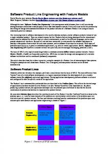
Figure 1 gives an overview of the space of variability mapping for SPLs as we see it. It should be noted, that for this paper we are interested only in static SPLs. Dynamic SPLs, where variability is resolved at runtime and is used to adapt the system to changing contexts, are out of the scope of our paper. Consequently, Fig. 1 only includes approaches to variability mapping that support static variability resolution. All of the approaches covered by this figure aim to support product derivation based on a selection of features from a feature model. To this end, they each provide some way to model the modifications of the target required if a particular feature has been selected or unselected. Based on how this is done, we distinguish a number of types of variability-mapping approaches:
Variability Mapping Declarative Positive Variability
Negative Variability
AHEAD [6]
Operational
Generic Model Transformations
Aspect-Oriented Modelling
Customised Model Transformations
Ziadi et al. [24] Botterweck et al. [25]
CVL [8]
VML* [11, 26] Gears [27]
Direct Annotation
Separate Annotation Model
Model Templates [7] Morin et al. [8]
FeatureMapper [9] pure:variants [23]
Fig. 1. Overview of approaches to variability mapping
1. Declarative variability mapping. In this category, we group approaches that model what changes are needed, but do not provide means of modelling how these changes should be achieved. Instead, the precise mechanism of change is encoded in the semantics of the models, to different degrees of formality, but typically encapsulated in a tool. The approaches discussed in the literature typically support either positive or negative variability: (a) Support for positive variability. Batory et al. [6] present A HEAD, an approach that views features as incremental modifications of base systems. Effectively, this leads to positive variability, where the addition of features leads to additions to the base system.9 (b) Support for negative variability. Negative variability uses models of the complete product line, removing elements associated with unselected features during product derivation. To specify which model elements are associated to which features, model elements are often tagged with feature names or feature expressions. These tags can either be embedded directly into the target model or they can be represented in a separate annotation model: i. Using direct annotations of the target model. Czarnecki and Antkiewicz [7] propose the use of a template model, which models all products in the product line. Elements of this model are annotated with so-called presence conditions. Given a specific configuration, each presence condition evaluates to true or false. If a presence condition evaluates to false, its associated model elements are removed from the model. Thus, such a templatebased approach is specific to negative variability, which might be critical when a large number of variations affect a single model. Moreover, presence conditions imply introducing annotations into the SPL model. Therefore, the actions associated with a feature selection are scattered across the 9
[6] in principle also allows features to represent non-monotonic modifications, which would lead to negative variability.
model, which could also lead to scalability problems. An implication of using annotations is that the modelling languages used for modelling an SPL need to provide means for annotating model elements (such as UML stereotypes). Other modelling languages cannot easily be supported. Morin et al. [10] provide an alternative approach to representing variability in models of a product line. Their approach is effectively based on tagging target model elements with variability information, similarly to [7] and FeatureMapper. However, instead of tagging with features or feature expressions, [10] tags model elements with whether they are optional, alternatives, mandatory, etc., as well as with inclusion constraints between different model elements. These concepts are expressed in a separate metamodel, which is woven into the target metamodel using their SmartAdapters approach to AOM [22]. Although Morin et al. use feature models to simplify the configuration of the variability expressed in their models, these feature models are derived directly from the target model assuming a simple 1-to-1 relation between features and model elements. Thus, their feature models are much closer to the solution space of a product line than the feature models we are discussing for the common case study. ii. Using a separate annotation model. FeatureMapper [9] is an approach very similar to the template-model approach of [7]. However, it uses an annotation model that is separate from the target model to store feature expressions and their associations with target-model elements. Because the annotations are not embedded directly into the target model, the target modelling language does not need to be changed and existing tools can be used directly. Also, by separating the target model and the variability specification, the target model can more easily be reused in another context. pure::variants [23] is an industrial-strength variant management tool that uses a separate model—a so-called family model—to store mappings between feature expressions and symbolic names to solution-space artefacts (such as file names, preprocessor definitions or URI to model elements). By default, the tool has no direct understanding of models and model elements. However, FeatureMapper was integrated into pure::variants recently, so that pure::variants feature models, variant models, and mapping models can be used in combination with FeatureMapper. pure::variants supports the configuration and derivation of variants of an SPL. 2. Operational variability mapping. In contrast to declarative approaches, operational approaches provide language constructs for specifying how target models must be modified when specific features are selected or deselected. We distinguish the following three categories of approaches from the literature: (a) Using generic model transformation languages. Ziadi et al. [24] and Botterweck et al. [25] both propose the implementation of product derivation processes as model transformations. Their proposals rely on the realisation of product derivations via a model transformation language. This strategy requires SPL engineers to deal with low-level details of model transformation languages.
(b) Using aspect-oriented modelling techniques. Haugen et al. [8] define the common variability language (CVL), which is a generic extension to DSLs for expressing variability. It provides three generic operators—namely value substitution, reference substitution, and fragment substitution—all of which are based on aspect-oriented notions of model weaving, but using these to express variability can lead to comparatively complex models. CVL is also based on model transformation, but proposes to extend the target modelling language with generic concepts for variability modelling. CVL distinguishes between so-called variation models and resolution models. A variation model is based on a modelling language extended with CVL concepts and describes all possible variations using the three standard CVL variability mechanisms. The resolution model is then used to select the variations to be included in a product model. (c) Using customised model transformation languages. VML* [11, 26] is a family of languages for variability mapping. A particular VML* language is effectively a model transformation language. However, different from the approaches in the first category, this model-transformation language has been customised both to the domain of SPLs and to the target modelling language. Thereby, SPL developers do not need additional knowledge about model-transformation languages or target-model metamodels. Instead, they can express required modifications using the same concepts and terminology they would use for producing the models in the first place. Gears [27] is an SPL framework that also supports product derivation. It started at the code level, and it has recently adapted for working at the requirements and/or model level with some specific tools [28], such as DOORS or Rhapsody. This tool has its own feature model, where each feature is seen as a variable with its own basic type (e.g. boolean or string). It also contains a mechanism to define variation points in software assets and a language for specifying how these variation points must be bound in order to produce a concrete product. For instance, we can declare a file containing a license agreement for a software product as a variation point, and associated different files containing different license agreements to that variation point. Then, using the language for variability binding provided with Gears, we can specify what specific license agreement must be included in a specific product depending on the feature configuration. Gears, allows to specify what actions should be carried out when a certain variants is selected or unselected, similarly to VML*, through a specific Gears capability called actuator. However, these actuators are based on manipulations of textual files, with no specific support for models, which implies that models need to me manipulated directly in their serialised form (such as in XMI format). This can make the implementation of actions very costly and time consuming. There are other aspect-oriented modelling approaches, such as MATA [19], XWeave [29], Reuseware [18], or RAM (Reusable Aspect Models) [30], which can also be used for software product line engineering and are not included in this classification. All these techniques provide mechanisms for encapsulating features in individual modules.
In these cases, features are considered as enhancements to an already existing core. MATA, for instance, provides mechanisms for encapsulating enhancements to an existing core as aspects, which are later composed—in case the corresponding feature is selected—with the core based on graph-transformation techniques. Nevertheless, these languages and tools focus on separating and encapsulating features as enhancements to an existing core, but they do not provide support to automate the product derivation process (i.e., aspects corresponding to selected features must be composed manually). Moreover, it is difficult to encapsulate fine-grained variations—such as changing attribute values. From the spectrum of approaches presented in this section, we have chosen two— namely FeatureMapper and VML*—which we apply to the common case study and compare with respect to a number of comparison criteria. To provide a full understanding of the spectrum, it would, of course, have been preferable to compare all approaches by applying them to the common case study. However, unfortunately this is not feasible. A key criterion for our selection was the fact that we know these two approaches and have full access to the tools and the original developers. Thus, we can ensure that we do not accidentally misuse or misrepresent the approaches, which could easily have happened with some of the other approaches. However, apart from this, we also selected the two approaches because they represent quite different categories from our classification in Fig. 1: FeatureMapper is a declarative approach for negative variability, while VML* is an approach for operational variability mapping. Thus, the results of our comparison should allow at least some initial conclusions about the relative benefits and drawbacks of these two broad categories.
3
Zooming in on the Case Study: Car Crises vs Flood Crises
To be able to demonstrate the approaches, we needed to refine the case study [1] for at least one additional product. The main motivation to model the additional product was to create models that contain significant differences between both instances of the product line and to evaluate the chosen approaches based on how they perform at modelling the variability that needed to be expressed in the different models. Therefore, we aimed to add two types of models and model elements: 1) such that would only occur in one of the two alternate products, and 2) such that would require some modifications (e.g., a different structure or different values) in each product. This section presents these refinements as a preparation for the rest of the paper.10 3.1
Flood Crisis Management System
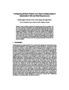
In addition to the car crisis management system (CCMS) from the case study, we have chosen to model a Flood Crisis Management System (FCMS). Figure 2 shows the configuration model (i.e., the selected features) for the FCMS. It can be seen that FCMSs have a feature set that is substantially different from CCMSs, but that they also share 10
Since not all models created for the case study can be presented in this paper, we provide the models on-line at http://featuremapper.org/files/TAOSD-AOM-2009/
a number of features. Features unique to the FCMS are underlined in the figure. Thus, features related with the use of the Navy, the pumping and repair missions, and the fact that the crisis may cover a large area are some examples of this uniqueness. We can also observe that there were features present in the CCMS which are not included in this configuration. Features related with investigation, nursing the wounded, sorting the wounded, police intervention, and the type of crisis (which is a major accident of type car crash) differs from the FCMS configuration. Figure 3 shows the use case model for an FCMS. A number of use cases have been added in comparison to the CCMS. For example, there are now the use cases ‘Execute Pumping Mission’ and ‘Execute Repair Mission’. These use cases only make sense for FCMSs, but not for CCMSs. As each use case is associated with at least one activity diagram detailing the concrete usage scenario, the FCMS model also contains additional activity diagrams. Note that even though some use cases are present for both products, they may still differ in the concrete underlying scenarios. This will be discussed in more detail for the ‘Execute Rescue Mission’ use case in the next subsection. Of course, the different products also require different designs and architectures. For example, the basic data structures required for both products are quite different, Figure 4 shows the data structures defined for FCMSs. In comparison, Fig. 5 shows the data structures defined for CCMSs. Furthermore, the FCMS makes use of a number of components that are not used by the CCMS and vice versa. For example, the FCMS uses the following components: ElectricityCompany, Navy, Army, ArmyVehicle, TelecommunicationCompany, and NavyBoat. The next subsection discusses the Rescue Mission as an especially interesting case, because although both products support this mission, they differ very much in their implementations of it. 3.2
Detailed Models of the Rescue Mission
The purpose of the rescue mission is to locate victims and remove them from the site of the crisis. This requires a quite different set of steps in the case of a car crash and a flood crisis. Figures 6 and 7 show two activity diagrams with the different scenarios. Notice that there is a common core, but that each product has some steps specific to it. In both cases, the rescue mission begins by transmitting injury information and attempting, where possible, to identify the victim(s). Next, additional conditions are checked. These are contingent on the type of crisis: In the car-crash scenario it makes sense to check whether the victim is locked in the car so that special actions need to be taken to remove him/her from the car. In the flood-crisis scenario, rescue is mostly about taking people out of the flood area. However, some victims, for example elderly or handicapped people, may require special assistance for this. In both cases, if the additional condition is true, the rescue mission is terminated after requesting another mission to be undertaken in response to the additional condition. If the additional condition is false, the rescue mission proceeds as normal, by administering first aid and deciding if the victim needs to be taken to a hospital. If no hospital is needed, no further action is required in the case of the car-crash scenario. For the flood-crisis system, however, all victims need to be taken to a safe place. We consider these are reasonable assumptions, based on real-life scenarios, on the original case study.
Fig. 2. Configuration model for a Flood Crisis Management System
Fig. 3. Use-Case Model for a Flood Crisis Management System
The two products also require a different set of realisation classes and data structures to appropriately represent the respective crisis, although they also share some common classes, which are depicted in Fig. 8. While for a car crisis the location of a victim is the same as the location of the crisis (apart, possibly from the exact vehicle in which the victim may be located), a flood crisis occupies a much larger area, so that victim location becomes a much more relevant information. Consequently, the Victim class provides a location attribute for storing the victim’s location. Furthermore, different types of victims may require different treatment (cf. also Fig. 6 and Fig. 7). Which types of victims need to be distinguished depends on the type of crisis. Finally, while some types of resources will be useful for both types of crises (e.g., Blankets), others are only relevant for one or the other (e.g., LifeJackets are only useful in a flood crisis). Consequently, different design models are required for the two different products. Figure 9 shows the models we will be using. Again, we consider these are reasonable assumptions, based on real-life scenarios, on the original case study. 3.3
Units of measurement
To show a specific type of variability mechanisms, we add a set of features dealing with units of measurement. The reason for this addition was that the case study can be completely modelled using positive and negative variability (cf. Sec. 2.1), and this
Fig. 4. Data structures for Flood Crisis Management Systems
Fig. 5. Data structures for Car Crisis Management Systems
change allows us to illustrate better how FeatureMapper and VML* can deal with model modifications. In particular, we add the MeasurementUnit feature group, which allows to choose between the alternatives ImperialSystem and MetricSystem. This feature allows our product line to be used in different countries using different units of distance measurements. Both the FCMS and the CCMS need to deal with geographical locations for identifying the places where the crisis take place and personal data of the victims. Fig. 10 shows the design classes for managing geographical locations. This design is shared by both the FCMS and the CCMS. These data structures include the class RoadwayLocation, which need to specify a length measurement. Depending on the country where this system is deployed, this length would be measured in kilometers or miles. An attribute called distanceUnit is added to the RoadwayLocation for configuring in which system units this class must work. So, depending on which country the system is deployed this attribute must be changed. The following two sections show how two different approaches to variability mapping can be applied to this case study, followed by a discussion of the two approaches in Sect. 6.
Fig. 6. Scenario for the rescue mission for the CCMS
4
Application of FeatureMapper to the Case Study
FeatureMapper [9, 31, 32] is an Eclipse-based tool that allows for mapping features to arbitrary modelling artefacts that are expressed by means of an Ecore-based language [12]. These languages include UML2, domain-specific modelling languages defined using the Eclipse Modelling Framework (EMF), and textual languages that are described using EMFText [13]. The mappings can be used to steer the product-instantiation process by allowing the automatic removal of modelling artefacts that are not part of a selected variant. To associate features or logical combinations of features (feature expressions) with modelling artefacts, the developer first selects the feature expression in FeatureMapper and the modelling artefacts in her favourite modelling editor (e.g., TOPCASED [33]). Next, she applies the feature expression to the modelling artefacts via the FeatureMap-
Fig. 7. Scenario for the rescue mission for the FCMS
per user interface. This mapping is later interpreted by a FeatureMapper derivation component. Depending on the result of evaluating the feature expression against the set of features selected in the variant, the modelling elements are preserved or removed from the model. Model elements that are not mapped to a specific feature expression are considered to be part of the core of the product line and are always preserved. This implies that the solution-space models contain all model elements that are used in any product of the product line. In Fig. 11 we show that we can model variants or product-specific variations in one model. The separation of concerns is realised by the actual mapping and various visualisation techniques that help the product-line developer in understanding the mapping between features and model artefacts. One such visualisation is depicted in Fig. 11 where the colouring of model elements accord-
Fig. 8. Design models for accomplishing abstract missions
ing to their associated feature expression is shown.11 Another visualisation is shown in Fig. 12 where only modelling artefacts mapped to the current feature expression are drawn normally, whereas all model elements that are not realised by this feature expression are shaded in grey. Because FeatureMapper implements these visualisations on a sufficiently generic layer to become independent of the concrete editor12 , using them does not require changing the editors and works on all GMF-based, tree-based EMF, and textual EMFText editors. This enabled us to map features of the CMS to requirements, architectural, and design models without changing or adapting FeatureMapper itself or any of the used modelling editors. 4.1
Modelling the mapping for requirements models
As depicted in Fig. 11 the use-case model contains all actors and use cases of both the CCMS and the FCMS. We used the mapping facility of FeatureMapper to map specific feature expressions to the elements of the use-case model. The feature expression have been identified by analysing the textual description of the different use cases and taking the different actors participating in a use case into account. In addition to the use cases included in the case study description, we extended the models as described in Sect. 3. For example, the feature expression Repair AND Electric Line was assigned to the actor Electrician, the use case Execute Electric Line Repair Mission, and the association between those two artefacts. The use case Execute Repair Mission was in turn only mapped to the feature Repair because it is also used when we include repairing of telecommunication lines in our product. Another possibility to create the mapping for the use case Execute Repair Mission 11
12
Since the colours used in this figure and others are likely not to be visible in a printout copy of the paper, we also provide the figures on-line at http://featuremapper.org/files/ TAOSD-AOM-2009/. FeatureMapper uses the Graphical Editing Framework (GEF) for graphical editors, the SWT TreeViewer for tree-based EMF editors, and the EMFText Editor, respectively.
Fig. 9. Design models for the rescue mission for the CCMS (top) and the FCMS (bottom)
is to include it only if Repair AND (Execute Electric Line Repair Mission OR Execute Telecomm Line Repair Mission) evaluates to true. We decided against this because it limits the extensibility of our mapping. In case we would decide to include another specialised repair mission in our product line, we would also need to update this mapping. The mapping of the various identified feature expressions to the use-case model artefacts exposed no problems. However, modelling all variants in one model can result in large models which might become hard to understand for some modellers. To address this, using other modularisation techniques (e.g., the decomposition of all use cases specialising Execute Mission into a separate package) is possible. Likewise to the mapping shown in Fig. 11, one would then map the appropriate feature expressions to the model artefacts in the decomposed models which are later on composed using a compositional approach, i.e., UML package merge or model weaving. Similarly to the use-case model we also mapped the features to activity models that contain inter-model variability. One example is the RescueMission (cf. Sect. 3.2). As can be seen in Fig. 13, inter-model variability is addressed in the FeatureMapper by modelling the variations in the model and mapping the corresponding feature expressions to the appropriate model artefacts. In the example, the feature expression Rescue AND CarCrash is mapped to the parts drawn in red colour and Rescue
Fig. 10. Data structures for dealing with geographical locations
AND Flood is mapped to the blue parts. Since Flood and CarCrash are mutually exclusive, it is ensured that the model tailored to a specific variant forms a syntactically and semantically correct model. In case a specific combination of features requires the inclusion of a complete model, e.g., the activity model for the Execute Pumping Mission use case which is only included if the feature expression Pumping AND Firemen (cf. Fig. 11) evaluates to true, FeatureMapper can be used to assign the respective feature expression to the complete model. 4.2
Modelling the mapping for architecture and design models
Similarly to the RescueMission activity model, the design model for the parts of the system relevant for the RescueMission contains modelling artefacts that are relevant for the CCMS and the FCMS (where some modelling artefacts only apply to one of the respective products). As can be seen in Fig. 14, variability also occurs at the granularity of attributes of classes, namely the attributes location and mobileNumber of the Victim class. Besides of addressing inter-model variability by modelling all variants of a specific subsystem in one model, FeatureMapper also allows to use compositional approaches for addressing variability. An example where cross-cutting changes to models are realised by model weaving based on graph-rewriting has been presented in [34]. Another possibility is mapping feature expressions to compositional operators that are directly available in UML, i.e., the UML PackageMerge relationship [35]. Using FeatureMapper, one can directly associate feature expressions to both the merged package (i.e., the package that contains variant-specific refinements to the receiving core package) and the merge relationship. In this case study we used this way of addressing variability for the realisation of the various ExternalServices. Instead of modelling all external services in one model (which might get too large and difficult to manage) we modelled the ExternalServices in dedicated UML Packages that are combined with the core of the CMS using UML PackageMerge relationships. Figure 15 depicts the realisation of the various ExternalServices in separate packages that are only merged to the core depending on the evaluation of the assigned feature expression. In this figure we also show FeatureMapper’s Variant Visualisation that gives an overview about the inclusion and exclusion status of different modelling artefacts depending on the selected
RemoveObstacle Witness AND SurveillanceSystem
Transport
SurveillanceSystem
Repair
Rescue AND PublicHospital
Repair AND ElectricLine
Observe
Repair AND TelecommunicationsLine
Pumping AND Firemen
AuthenticationSystem
Core
Fig. 11. Use-Case Model of the CMS displayed in FeatureMapper with enabled colouring of model elements and the legend depicting the corresponding feature expressions.
set of features from the feature model. In this example we included all external services except for Army and ExternalCompany which is why those packages are coloured different from the other ones. As described in Sect. 3.3 we have extended the product line with a MeasurementUnit feature which consists of the two alternatives MetricSystem and ImperialSystem. Depending on the feature selection, the respective measurement kind should be used in the design models of the CMS product line. Figure 16 depicts the part of the design models which is concerned with describing different kinds of Location. Depending on the selected feature expression, the attribute distanceUnit of the RoadwayLocation class should have a default value according to the feature selection. In Fig. 16 we show the variant for MeasurementUnit AND MetricSystem. To actually assign such changes of model properties to feature expressions, FeatureMapper has a recording mode, where the developer first selects the appropriate feature expression and then performs the actual change to the property (e.g., changing element names, cardinalities, or default values) in the model. This change is recorded internally
Fig. 12. Use-Case Model of the CMS displayed in FeatureMapper with enabled Realisation Visualisation that highlights the model elements associated with the current feature expression.
and assigned to the feature expression in FeatureMapper’s mapping model. For these changes, only one version can be shown directly in the diagrams at any one time. FeatureMapper’s Property Changes View highlights the model elements where property changes occur in the model (cf. Fig. 16) in red. The different alternatives can then be inspected in a dedicated dialog as depicted in Fig. 17.
5
Application of VML* to the Case Study
This section shows how the Variability Modelling Languages from the VML* language family [11] can be applied to the case study. VML* is a family of languages for modelling the mapping between feature models and other models of an SPL (called target models). Each language is customised for the specific target modelling language for which it is to be used. For instance, if in a SPL we are using UML activity diagrams, using VML* we can create a language specifically designed for managing variability in UML activity diagrams. VML* provides a generative infrastructure for efficiently developing such customised languages. To apply VML* to the case study, we must first develop the specific customised VML languages we need. Notice that this step must only be taken once; the languages created can be reused for other SPLs as long as the feature and target modelling lan-
Fig. 13. Activity Model of the RescueMission where elements are coloured according to their feature mapping (Flood is blue whereas CarCrash is red).
guages remain the same. In Sect. 5.1, we will briefly discuss how to create the languages required for this case study. We then discuss the application of each individual language. 5.1
Creating VML languages
VML languages are defined using a so-called language-instance descriptor [11]. A complete support infrastructure can then be generated from the language-instance descriptor. The language-instance descriptor is a domain-specific metamodelling language [36] that allows language developers to model only those parts of a new VML language that need to be customised. All other parts of the language and its support infrastructure are generated and, thus, reused for each language. Figure 18 shows an excerpt from a language instance descriptor for one of the customised languages we will need for this case study: VML4RE, a language for mapping
��������
�������
�������
�����������
�
� � ��������
�
�
������������� �
����
� ������������ ����
����
� � ����
������ � ��������������������� ����������� � ��������� ��������������� ���� ���� � ������������������������������ ���� ���� � ����������������������� � � � ������������������������������� � �� ��������������� � ����������� � ������� � ��������������������� � �������� ����������������� � ���������������������������
���� ����������������
� ����� ����������
�������
�
����������������� � �����������������������������
� ����������� ��������������� ������� ����� �������� �������� ������ ������� �����
��������� � ���������������������
�
��������������� �������� ����� �������� ���������� �������
����������� � ����������������
� ��������������� � ����������������������
��������������� ������������ ����� ������ ���� ����������
Fig. 14. Class Model of the RescueMission where elements are coloured according to their feature mapping (Flood is blue whereas CarCrash is red).
����������������������
��������� ���������������
���������
�������������������
��������� ����
���������
��������������
��������� ���������������
��������� ������
Fig. 15. Package Model of the ExternalServices using merge relationships between packages to increase modularisation. ������������ ������������������ � ��������������� � ������� �������� � ���������������
��������������� ������������ ���������� �����
������� � ������ ��������� � �������������������
��������
�������������������� � �������� ���������������������� � �������������������������������
��������������� � ��������������� � ����������������������������������������
Fig. 16. Class Model for different types of Location including property-level variability at the distanceUnit attribute of RoadwayLocation depicted in FeatureMapper’s Property Changes View that highlights parts of models with property-level variability.
Fig. 17. Dedicated dialog in FeatureMapper to inspect property-level variability.
from feature models to requirements models, specifically UML Use Case and Activity diagrams [37]. The full language will be used in Sect. 5.2. The language-instance descriptor makes use of an openArchitectureWare Xtend [38] extension file defining a number of model-transformation operations. For example, in the first section called ‘features’ (Lines 4–8), the language-instance descriptor defines the metamodel for feature models that can be used with VML4RE and also provides the name of an Xtend operation that can extract all defined features from such a feature model. The next section (Lines 11–16) similarly defines the metamodel for target models and a function for finding a set of model elements based on some textual description called a designator. VML languages use a notion of pointcuts for referencing points in target models that need to be manipulated when a certain feature has been selected. Thus, the designators to be interpreted by this function may contain wildcards. The ‘actions’ section (Lines 22–29) syntactically defines what actions are available in VML4RE. It can be seen that these actions are specific to the manipulation of use cases and activities. Their semantics is further specified in the final ‘aspects’ section, that allows to define a number of different semantics for different evaluation aspects, such as product derivation (specified in the ‘transformation’ aspect) or tracing. For the product-derivation semantics, we need to specify another adapter (Lines 35–38) that is able to interpret product configurations and extract the selected features. Next, we provide an Xtend implementation function for each action. For the tracing semantics (Lines 48–51), we define pointcuts into our transformation implementation identifying places where new model elements are created or existing ones deleted. Based on the above approach, we have defined two languages: VML4RE for mapping features to requirements models and VML4Arch for mapping features to architectural and design models. Once we have thus defined the necessary languages, we can apply them to our case study, as will be demonstrated in the following subsections. 5.2
Modelling the mapping for requirements models
In this section, we show the mapping for requirements models; that is, the set of core requirements models and how VML4RE can be used to derive product requirement models. Before using VML4RE to manage variability, it is necessary to decide which models are going to be considered as core; i.e., the models which will be manipulated
01 02 03 04 05 06 07 08 09 10 11 12 13 14 15 16 17 18 19 20 21 22 23 24 25 26 27 28 29 30 31 32 33 34 35 36 37 38 39 40 41 42 43 44 45 46 47 48 49 50 51 52
// Define a new language called vml4req vml instance vml4req { // This section defines the type of variability model and how to access it features { metamodel "/bin/fmp.ecore" // Extracts all variability units from a variability model function "getAllFeatures" } // This section defines the type of target model and how to access it target model { metamodel "UML2" type "uml::Package" // Metamodel type of a model // Function to interpret pointcut designators function "dereferenceElement" } // Importing plugins and external specifications ... // Syntactical definition of available actions actions: createInclude { params "List[uml::UseCase]" "List[uml::UseCase]" } insertUseCase { params "String" "uml::Package" } ... // Definition of available evaluation aspects aspects: transformation { // Evaluation for product derivation // Defines adapter for product-configuration access features { type "String" function "getAllSelectedFeatures" } // Definition of the semantics of actions as model transformations createInclude { function "createIncludes" } insertUseCase { function "createUseCase" } ... } tracing { createOps “create* (*)” removeOps “remove* (*)” } }
Fig. 18. Excerpt from a VML* language-instance descriptor for a VML language for mapping feature models to requirements models
Fig. 19. Core use case model for the Crisis management System.
according to the different variants and combinations between them to obtain the product models. Figure 19 shows the considered core use case model for the CMS. Here, we followed a positive variability approach, so this use case model contains use case model elements related with mandatory functionalities only. For example, the model contains the use case Execute Mission. However, at this stage, it does not contain any details about which type of missions are supported by the system, since specific missions are all optional in the feature model of CMS. Since requesting external resources and assigning internal resources are mandatory functionalities across the SPL, they are also present in this figure. We have also specified the variability for more fine grained models, such as scenarios associated with each use case, represented through activity diagrams. For activity diagrams, we have considered as core models several scenarios represented with activity diagrams, such as Assign Internal Resource, Execute Pumping Mission, and Execute Super Observer Mission. For Execute Pumping Mission and Execute Super Observer Mission we adopted a negative variability approach, so if any of the related features are not selected in a configuration, these model elements are removed from the model. We adopted this strategy since we believe that in some situations, it is preferable to model visually than constructing the same model using a set of textual descriptions. Another observation is that the behaviour included in this scenario is not shared between the two considered configurations, so we haven’t identified too fine grained variability for this scenario. For the rescue mission, we identified some variation points for each of the different configurations (car and flood crisis) but also some common parts. Figure 20 shows the considered core activity model for the rescue mission. This core model contains all behavioural elements which are shared by both car and flood crisis configurations. Figure 21 shows an excerpt of the VML4RE specification for the crisis management system SPL. Lines 6–10 show the variability management when the Rescue feature is selected in a configuration. Given a configuration, if the feature expression in Line 6 evaluates to true, a use case with name Execute Rescue Mission
Fig. 20. Core Activity Diagram for the Rescue Mission Scenario.
is created (Line 7) and an inherits relationship from this use case to the use case ExecuteMission (which was considered as core) is created (Line 8–9). VML4RE can generate trace links from features to requirements model elements based on actions, since there is implicit trace information in VML4RE specifications. However, VML4RE also offers a specialized operator which allows to explicitly trace features to requirements model elements. In this VML4RE specification, we can see that Lines 1115 define explicitly a set of trace links from the feature Rescue and activity model elements. In this piece of VML4RE code, we are defining trace links from the feature Rescue to the core actions of Rescue activity model depicted in Fig. 20. Line 18– 23 show the variability management for the Public Hospital feature. If this feature is selected, actors such as Hospital Resource System and First Aid Worker and respective relationships are also created. Notice that VML4RE’s pointcut expressions allow us to connect all of these actors to their appropriate use cases in one action invocation (Lines 21–22). For this variation point, we use a positive variability approach. The creation of the use case model elements for the feature Public Hospital depends on the previous execution of the actions related with the variant Rescue (the action depicted in Lines 6–16), so an order of execution must be specified here. VML supports the definition of order of execution between feature expressions. To define an order for this situation, we have named each of the features expressions (rescue and public hospital). The specification of the order of execution can be found in Line 66. Lines 25–33 show the set of actions to be executed if both Rescue and CarCrash features are selected. These actions construct the scenario for the rescue mission in the context of a car crisis (one of the products available for this SPL). The resulting scenario
01 02 03 04 05 06 07 08 09 10 11 12 13 14 15 16 17 18 19 20 21 22 23 24 25 26 27 28 29 30 31 32 33 34 35 36 37 38 39 40 41 42 43 44 45 46 47 48 49 50 51 52 53 54 55 56 57 58 59 60 61 62 63 64 65 66
import features ; import core ; concern CrisisSystem { variant rescue for Rescue { insertUseCase ("ExecuteRescueMission", "CrisisManagementSystem"); createInherits ("CrisisManagementSystem::ExecuteRescueMission", "CrisisManagementSystem::ExecuteMission"); trace trace trace trace trace }
("ExecuteRescueMission::TransmitInjuryInformation"); ("ExecuteRescueMission::IdentifyVictim"); ("ExecuteRescueMission::RetriveMedicalRecord"); ("ExecuteRescueMission::AdministerFirstAid"); ("ExecuteRescueMission::BringToHospital");
variant public_hospital for PublicHospital { insertActor ("HospitalResourceSystem", ""); insertActor ("FirstAidWorker", ""); createAssociation (or( "HospitalResourceSystem", "FirstAidWorker"), "CrisisManagementSystem::ExecuteRescueMission"); } variant for and ( CarCrash,Rescue) { createAction ("RemoveVictimFromCar", "ExecuteRescueMission"); connectActivityElements("ExecuteRescueMission::dn2", "ExecuteRescueMission::RemoveVictimFromCar", "[isVictimLockedInCar]"); connectActivityElements("ExecuteRescueMission::RemoveVictimFromCar", "ExecuteRescueMission::FinalNode", ""); connectActivityElements("ExecuteRescueMission::dn3", "ExecuteRescueMission::FinalNode", "[false]"); } variant for not Rescue { removeElement("ExecuteRescueMission");//removes the core activity model } variant for and (Rescue ,Flood) { createAction ("RequestSpecialAssistance", "ExecuteRescueMission"); connectActivityElements("ExecuteRescueMission::dn2", "ExecuteRescueMission::RequestSpecialAssistance", "[isVictimHandicapped]"); connectActivityElements("ExecuteRescueMission::RequestSpecialAssistance", "ExecuteRescueMission::FinalNode", ""); createAction ("RecoverVictim", "ExecuteRescueMission"); connectActivityElements("ExecuteRescueMission::dn3", "ExecuteRescueMission::RecoverVictim", "[false]"); connectActivityElements("ExecuteRescueMission::RecoverVictim", "ExecuteRescueMission::FinalNode", ""); } variant for Observe { insertUseCase ("ExecuteSuperObserverMission", "CrisisManagementSystem"); createInherits ("CrisisManagementSystem::ExecuteSuperObserverMission", "CrisisManagementSystem::ExecuteMission"); insertActor ("SuperObserver", ""); createAssociation ("SuperObserver", "CrisisManagementSystem::ExecuteSuperObserverMission"); } variant for not (Observe){ removeElement("ExecuteSuperObserverMission"); } } order (rescue, public_hospital );
Fig. 21. Excerpt from the VML4RE specification for crisis management systems
from executing this set of actions is the activity diagram depicted in Fig. 6. Variability has also been defined for the rescue scenario in the context of a flood crisis system. Lines 39–50 show the set of actions to execute in the core rescue mission activity model, if both features Rescue and Flood are selected. One important note is that in order to use connect actions, the elements to connect should be named so that they can be referenced. One example of this is in Line 41, where dn2 indicates one specific decision node of the activity diagram. Since Rescue is an optional feature, it is also possible to have configurations in which the feature is not selected. For these configurations, the core activity mode for Rescue Mission should be removed. Lines 35–37 show the application of the action removeElement (modelElement) for these cases. Figure 21 also contains the variability management specification for the Observe Mission. When the feature Observe is selected, use case model elements related with this feature are constructed for the product model. As we said previously, for the Execute Super Observer Mission scenario (Activity Diagram) we adopted a negative approach. This means that the corresponding activity diagram was included in the core model, and in the case of unselection of this feature (Line 61) in a configuration, we remove this activity diagram (Line 62). The trace links generated by VML* (and thus by VML4RE) can be used to visualise the mapping between features and model elements. Figure 22 depicts part of the generated trace links for the Rescue feature, considering the flood crisis product. The AMPLE Traceability Framework (ATF) [39] offers several visualizations to show trace links. The left part of Fig. 22 shows a tree-based view and the right part shows a graph-based view. In the tree-based view, we can see the trace link between Rescue and Identify Victim. This trace link was created because of the explicit use of the action trace in the VML4RE specification (Line 12 of Fig. 21). On the other hand, a trace link has been generated from Rescue to the use case Execute Rescue Mission, because of the action present in Line 7. The graph-based figure on the right, shows several links created for the flood crisis product. In this view, the elements such as use cases, packages, actors, activity diagrams, actions and features are represented as nodes. Edges are used to represent a link between two elements. For each visual element (a node or an edge), we can also see the properties (type and name) of that element. For example, in Fig. 22 (graph based view) we can see the properties for the feature Rescue at the top of the window. In this figure, we have also emphasized the set of trace links for this feature using a red rectangle. This view is useful to see how elements are linked—for example to see which requirements elements are shared between different features. We can see that there are two requirements elements (RecoverVictim and RequestSpecialAssistance actions) which are shared between the Flood and Rescue features. These requirements elements were inserted when generating the product model, since the feature expression in Line 39 of Fig. 21 was true according to the flood crisis feature model configuration. 5.3
Modelling the mapping for architecture and design models
This section describes the results of applying VML4Arch [26, 40] to the Crisis Management System. VML4Arch is a language for specifying the connection between feature models and UML 2.0 architectural models.
Fig. 22. Visualization of generated trace links from the feature Rescue to requirements model elements for the flood product using a tree-based view (left) and a graph-based view (right)
Figures 23 and 24 show the aspect-oriented decomposition of the software architecture. The Core package contains the elements that are common to all the products. The elements for interacting with a specific external service, such as the Police, are encapsulated into a separate UML package (cf. Fig. 23). The same applies to the elements for managing each particular kind of crisis (cf. Fig. 24). Thus, the elements that are common to the data structures for accomplishing any kind of mission (cf. Fig. 8) would be placed in the Core, specifying these data structures must be included in any kind of product derived from this reference architecture. This design is then refined in the CarCrisis and FloodCrisis packages. Each particular kind of crisis adds its own kind of missions and the specific data structures that are required for each kind of mission. For instance, the CarCrisis aspect adds the classes and relationships that are specific for accomplishing CarRescueMissions, i.e. the data structures depicted in Fig. 5. Similarly, the data structures depicted in Fig. 5 would be added to the FloodCrisis package. Thus, depending on which features are selected, we need to combine a different set of packages. What packages need to be combined with the core in order to create a concrete product is specified using VML4Arch (cf. Fig. 25). The product derivation process determined by this VML4Arch specification is as follows: First of all, a new UML package representing the final product being derived is created. This package is called MyCrisisManagementSystem and it is initially empty. This empty package will merge those packages that correspond to selected features, e.g. CarCrisis or Police. The piece of code for creating this package (Fig. 25, line 06) is associated to the root feature of the feature model. Moreover, the MyCrisisManagementSystem package merges the Core package (Fig. 25, line 07), which represents the minimum and core functionality that any Crisis Management System must have. Since the root feature is always selected, this piece of code is always executed and the MyCrisisManagementSystem package is always created and a merge relationship is initially created between this package and the Core package.
Fig. 23. Aspect-oriented decomposition of the Crisis Management System (I)
Fig. 24. Aspect-oriented decomposition of the Crisis Management System (II)
00 01 02 03 04 05 06 07 08 09 10 11 12 13 14 15 16 17 18 19 20 21 22 23 24 25 26 27 28 29 30 31 32 33 34 35 36 37 38
import features ; import core ; concern CrisisManagementSystem { variant for CrisisManagementSystem { createPackage ("MyCrisisManagementSystem", ""); merge ("MyCrisisManagementSystem", "Core"); } variant for CarCrash { merge ("MyCrisisManagementSystem", "CarCrash"); } variant for Flood { merge ("MyCrisisManagementSystem", "FloodCrisis"); } variant for SurveillanceSystem { merge ("MyCrisisManagementSystem", "SurveillanceSystem"); } variant for not SurveillanceSystem { remove ("SurveillanceSystem"); } variant for MetricSystem { setDefaultAttribute ( "Core::Datatypes::BasicDatatypes::RoadwayLocation.distanceUnit", "Core::Datatypes::BasicDatatypes::RoadwayLocation::KILOMETRES"); } variant for ImperialSystem { setDefaultAttribute ( "Core::Datatypes::BasicDatatypes::RoadwayLocation.distanceUnit", "Core::Datatypes::BasicDatatypes::RoadwayLocation::MILES"); } } // CrisisManagementSystem
Fig. 25. VML4Arch specification for the Crisis Management System
Merging packages is expressed in VML4Arch using the merge action. UML merge dependencies in the UML model are used to express dependencies between coarsegrained variants. These dependencies represent architectural information about the product line as a whole and are provided by the SPL architect. They must be maintained under any circumstances. The UML merge dependencies introduced through merge actions express which coarse-grained variants should be included in the architecture for a specific product. The merge action will only add its corresponding dependency if this is not already given by transitivity. Hence, given the following merge dependencies in the model: A --merge--> B, B --merge--> C, calling merge (A, C) will not have any effect since that dependency is already in the model by transitivity. Also, if any other direct dependency becomes redundant, it is removed—for example, given additionally D --merge--> B, calling merge (A, D) will lead to the final situation of A --merge--> D, D --merge-->B, B --merge--> C. Thus, the merge dependencies introduced in the VML4Arch specification are effectively those depicted in Fig. 15, where CrisisManagementSystem corresponds to MyCrisisManagementSystem. Figure 23 may give the impression that all types from the Core package are duplicated throughout the product-line model. However, because a product is eventually represented by a single package merging all coarsegrained variants, these redundant copies of Core concepts will be merged into one again, removing all duplication and redundancy.13 Fine-grained variations are managed through different VML4Arch operators, which allows, basically, to modified elements from an architectural design model, or remove them. We illustrate two different cases for this. In the first case, the Core package contains a set of data structures for identifying geographical locations (cf. Fig. 10), which must measure distances in different units depending on the country where the system is deployed. It is decided that, by default, the system is configured for working with the metric system units, so KILOMETERS is specified as default value for the distanceUnit attribute (cf. Fig. 10). In case the Imperial system was selected, this value should be changed. This is made through the VML4Arch code contained in lines 32-36 of Fig 25, which basically says the default value for this attribute must be set to MILES. In the second case, let us suppose the first-aid material is an optional feature, instead of mandatory, inside this product line. WaterBottles and Blankets are considered first-aid material. We can think on separating WaterBottles and Blankets in a separate UML package and merging this package with the CarCrisis package. Nevertheless, as previously commented, this technique would quickly lead to the creation of a large number of small and practically meaningless aspects, with, in most of cases, a complex set of dependencies among them, which would make the design unmanageable. Instead of following this positive strategy, we follow a negative strategy. Thus, we simply leave the WaterBottle and Blanket resource in the design model, and in case the first-aid material feature were not selected, these classes are simply removed from this design model. It should be noticed that this removal should only 13
Note that this implementation of merge is specific to VML4Arch. Other VML* languages may also need a similar action. They are free to use any implementation needed, so they could, for example, be based on [41].
01 02 03 04
variant for and (CarCrash, not (FirstAidMaterial)) { remove ("CarCrash::Datatypes::WaterBottles"); remove ("CarCrash::Datatypes::Blankets"); }
Fig. 26. VML4Arch specification for removing FirstAidMaterial
happen if the CarCrisis option has been selected. Otherwise, if the CarCrisis option is not selected, the package containing this design would be not selected and the removal of these classes would not have any effect, as we can consider they were already removed as the package is not included in the final product. This is specified using the feature expression depicted in Fig. 26, line 01. It establishes that, if CarCrisis has been selected, but FirstAidMaterial has not been selected, the classes representing WaterBottles and Blankets would also be removed.
6
Discussion and Comparative Analysis of the Two Approaches
In the previous sections, we have shown how two approaches to variability mapping can be successfully applied to the case study. Both approaches were able to produce product models for the two products described in Sect. 3. In this section, we provide a comparative analysis of the two approaches. Table 1 gives an overview of the comparison criteria we have used and how they are met by the two approaches. In the following, we first give a more detailed description and motivation of each criterion, followed by a detailed discussion of how the two approaches meet each criterion. 6.1
Comparison Criteria
Our comparison of VML* and FeatureMapper is mainly based on the application of the two approaches to the common case study, as discussed earlier in this paper, but also on our previous experience with these approaches in other case studies and application scenarios. We have selected nine comparison criteria. These criteria were chosen because they represent general concerns for variability mapping. In particular, the nine criteria can be grouped into three groups based on the general variability-modelling concern they are related to: 1. Expressiveness. This group assembles criteria that describe the variability space that can be covered by a particular approach. These criteria are: (a) Modelling Languages supported; (b) Variability Mechanisms supported; (c) Support for Feature Expressions; and (d) Support for Feature Cardinality and Cloned Features. 2. Useability and Analysis. This group assembles criteria that describe the kinds of analyses and evaluations that can be performed and the useability benefits and drawbacks of a particular approach. These criteria are:
Table 1. Overview of the comparison between FeatureMapper and VML* Criterion Expressiveness Modelling Languages Supported
FeatureMapper Fully Generic
VML* Generic through customisation Modification All
Variability Mechanisms Supported Negative and Only Support for Feature Expressions Supported Support for Feature Cardinality and No Support Cloned Features Useability and Analysis Support for Automatic product Supported derivation Analysis Support Feature Model, Mapping Model, Multiple Visualisations Accessibility of the Mapping Separate model maintained by tool Model Real-World Models Scalability Direct Annotation Detection of Broken Mappings Support for Model Evolution
Supported No Support
Supported Trace Links Separate model maintained by SPL engineer Pointcut Expressions No Dedicated Support
(a) Support for Automatic Product Derivation; (b) Analysis Support; and (c) Accessibility of the Mapping Model. 3. Real-World Models This group assembles criteria that describe how the approaches deal with properties of real-world models. In particular, these criteria are: (a) Scalability; and (b) Support for Model Evolution. In the following, we briefly discuss each criterion in more detail before Sect. 6.2 applies them to a comparison of VML* and FeatureMapper. Modelling languages supported With the advent of domain-specific modelling languages, a variability-modelling approach that only supports one modelling language is almost not usable. Some level of genericity in such an approach is, therefore, highly important. This is especially true with regard to the target modelling language; that is, the language in which the SPL reference model is expressed. However, because to date there is no commonly agreed standard for feature modelling and a range of different types of feature models and tool realisations is available, a variability mapping approach should also have some genericity with regards to the feature-modelling approach used. Consequently, for this criterion we compare if and how FeatureMapper and VML* can support different modelling languages both for feature modelling and for the target models. Variability mechanisms supported As discussed in Sect. 2.1, we can distinguish three major variability mechanisms:
1. Negative Variability. 2. Positive Variability. 3. Modification of Model Elements. Both, negative and positive variability, have benefits and drawbacks: Negative variability uses one model of the complete product line, this model can become very complex as it has to contain model elements for any product in the product line. Some parts of such a model may even contradict each other, making the model potentially very difficult to analyse and understand. Positive variability avoids this problem by separating model elements for each different product into different models. At the same time, this means that there can potentially be a large number of model fragments describing the SPL as a whole, making it difficult to get an easy overview of the SPL. This can potentially make it more difficult to spot feature interactions in the models. In contrast, with a negative variability approach many feature interactions can be identified directly, as all model elements are added to the same model. Therefore, it would be beneficial for a variability-modelling approach to support all forms of variability modelling—possibly even within the same specification—leaving the choice to the SPL designer based on what is best for each situation. Consequently, for this criterion we compare which variability mechanisms FeatureMapper and VML* support. Support for Feature Expressions The relationship between features and model elements is typically not one-to-one. Instead, a particular combination of features may be realised by a single model element or a single model element may be required for a set of different features (regardless of combination) but not by other features in the SPL. A typical technique to enable expression of such more complex mappings is the use of feature expressions; that is, boolean expressions over feature names. Feature expressions are evaluated over product configurations; that is, concrete selections of features from a feature model. A simple feature expression consisting of a feature name only evaluates to true if the named feature is selected in the product configuration. Based on this, more complex feature expressions follow the standard rules for logical combinators. Consequently, for this criterion we compare if and how FeatureMapper and VML* support feature expressions in their variability models. Support for Feature Cardinality and Cloned Features Feature models in their original form [5] are very good at representing configurative variability, but less good at more structural forms of variability. This issue has been addressed, at least partially, by more advanced forms of feature models, such as for example cardinality-based feature models [42]. Even though there are still many situations were it is better to use a domain-specific language for expressing structural variability (for example, where variations in workflows need to be expressed), cardinality-based feature models take an interesting step towards structural variability by allowing features to be selected more than once and with different configurations of their sub-trees. Mapping such so-called cloned features to target model elements poses a number of interesting challenges to variability mapping, which go beyond what is required for the criteria above. Therefore, we introduce a separate criterion for this capability.
Consequently, for this criterion we compare if and how FeatureMapper and VML* provide support for mapping cloned features onto target-model elements. Support for Automatic Product Derivation Product derivation refers to the creation of models and implementations for a particular product in an SPL based on a selection of a subset of the features from the SPL’s feature model. A central goal of all variability mapping is to automate product derivation as much as possible based on an explicit description of features, variant models and implementations, and the mapping between these. Consequently, for this criterion we compare if and how FeatureMapper and VML* automate product derivation. Analysis Support Another good reason for making the relation between features and target model elements explicit is that it enables analysis. Variability models can be analysed in many different forms ranging from visualisations of different products or feature expressions or the generation of tracing information for example for changeimpact analysis all the way to formal consistency analysis (e.g., [43, 44]). Consequently, for this criterion we compare the types of analyses enabled by FeatureMapper and VML*, respectively. Accessibility of the Mapping Model Variability modelling means to make the relationships between features and target models explicitly. However, this can be done in a variety of ways and these have an effect on the useability of a variability-modelling approach in particular scenarios. Here, we focus on two dimensions: 1) How is the mapping expressed, and 2) How is the mapping model managed. Consequently, for this criterion we compare how FeatureMapper and VML* express the mapping as well as how they each manage the variability model and allow SPL developers access to it. Scalability Real-life SPLs can have large feature sets and very large models. Thus, scalability of any approach to modelling variability becomes an important issue. While the case study discussed in this paper is not big and detailed enough to obtain precise data on scalability, some qualitative arguments can be extracted. Our experience with this and a number of other case studies indicates that while some properties of the variability modelling approach can have an impact on scalability, the structure of the SPL model has by far the greater impact. This is so because effectively with SPLs it is inevitable to make explicit every connection between any feature and its corresponding model variations. That is, the amount of information to be represented is determined mainly by the size of the feature and SPL models and the inherent complexity of their relationship. The simpler the relationship between the two, the more easily can it be represented and the larger the SPLs that can still be handled. At one extreme, Feature-Oriented Software Development [45] proposes a direct one-to-one mapping between features and implementation modules, making explicit mapping representations virtually unnecessary. However, in practice this cannot always
be achieved perfectly and may lead to unnecessarily many unnecessarily small implementation modules, so an explicit mapping representation is still needed. In our discussion above, we have seen how the choice between variability mechanisms can influence the scalability of our variability models. For example, in the VML4Arch example, we saw how using UML packages and UML merge dependencies could significantly reduce the amount of VML4Arch code to be written for a variability specification. If we were to describe the necessary elements of the CarRescueMission design model as part of the variability model, we would need to create 9 elements (7 classes plus 2 enumerations). Moreover, we would also need to create 11 relationships among these elements. So, we would need approx. 20 lines of VML4Arch code for creating the design model depicted in Fig. 9. Using UML packages and merge relationships, we can reduce the number of VML4Arch lines of code to just one. Moreover, we need only one line of code independently of the size of the model placed in a UML package, as the only thing we need to express is that this package needs to be included in the final product. Each new type of crisis management system only requires adding another package and one line of VML4Arch code. However, at the same time, it is not sensible to represent every variation in its own package. If we were to do so even for, for example, such small variations as the difference between using the imperial and the metric measurement system, we could easily end up with a large number of packages with very little meaningful contents, fragmenting the SPL model to the point of incomprehensibility. While this discussion applies equally to both approaches discussed, there are some differences between the approaches which may affect scalability. Consequently, for this criterion we provide a qualitative discussion of different capabilities FeatureMapper and VML* provide for dealing with large models and feature sets.
Support for Model Evolution SPLs are not static and, consequently, variability models cannot be static artefacts. Therefore, it is interesting to discuss what, if any, support for evolution a variability-modelling approach provides. There is a number of dimensions to this criterion. It includes evolution of the metamodels for features or target modelling language. It also includes, however, evolution of the actual feature and target models and the need to co-evolve the variability models along with them. The common case study does not provide any evolution scenarios. Therefore, we cannot directly use the experience from our application of FeatureMapper and VML* to the common case study to provide insights in how the two approaches cope with evolution. However, because we feel this criterion is essential in any variability mapping approach, we decided to include at least some analytical discussion of how FeatureMapper and VML* could deal with model evolution.
6.2
Comparative Analysis of VML* and FeatureMapper
In this subsection, we use the criteria from the previous subsection to compare FeatureMapper and VML*.
Modelling Languages Supported While both FeatureMapper and VML* are generic and work for arbitrary modelling languages, there are some differences that are worth discussing in more detail. FeatureMapper is a tool that can work with arbitrary EMF models and supports a range of different editors for these models, including arbitrary GMF-based editors, the standard EMF tree editors, and EMFText-based text editors. In contrast, VML* produces mapping languages for specific modelling languages. It is, thus, also generically applicable for any EMF model, but only if an appropriate VML language has previously been defined. Consequently, there is an added initial cost to using VML* in a project, in particular if a large number of project-specific or domain-specific languages are used. On the other hand, because VML languages are customised for each modelling language used, they can take into consideration the semantics of these modelling languages, providing much more powerful actions than generic direct mappings between features (or feature expressions) and model elements. As an example, consider VML4Arch’s connect (C1, C2, I) action, that connects components C1 and C2 via interface I. To express the same in FeatureMapper, we would have to produce mappings to the appropriate ports in C1 and C2 as well as to the dependencies between these ports and the interface I. Although connect does not currently support this, it could even easily be extended to create interface I if it does not exist yet. The cost of customising VML* to a particular target language can be decomposed into two parts: (i) the effort needed to implement adapters for dealing with different meta-models and (ii) the effort needed to implement the actions required. With respect to the former, both VML* languages we have discussed (VML4RE and VML4Arch) use feature models based on the FMP plugin for Eclipse and UML Models using the UML plugin for Eclipse, so we were easily able to reuse this code between the two languages. It should be noted, though, that even so the code needed is relatively compact and easily understood (at about 20 lines of recursive navigation code for accessing the UML models; accessing FMP models is more complex due to some special particularities of the FMP metamodel, which hinders its navigation when Xtend is used as model transformation language.) In terms of the effort needed to implement the actions in a VML* language, Table 2 provides an overview of some data on the VML4Arch and VML4RE implementations. In particular, it shows the number of lines of transformation code required, on average, per action implementation as well as a subjective judgment of how many of these action implementations were difficult or easy to understand, code and test. More substantive empirical studies are required to provide more robust knowledge about the cost involved in customising VML* to a particular target language, overall because the effort involved in the development of a new VML* language starts to be cost-effective when this language is applied to the development of several SPLs or a same SPL evolves and the VML* language helps to reduce the maintenance cost. This task goes beyond the scope of this paper. However, already from Table 2 it can be inferred that all actions for VML4RE could be implemented with reasonable effort. In the case of VML4Arch, there are some actions, such as merge, which required a bigger effort. It should be taken into account this action must carry out several checks to avoid redundancies, which increases its complexity. But at the same time, it encapsu-
Table 2. Qualitative and Quantitative Estimated Effort for the VML4RE and VML4Arch languages Criterion Average number of code lines per action Difficult action implementations Action implementations medium difficulty Easy action implementations
VML4RE 5
VML4Arch 14.54
None None
2 2
All
9
lates more work than more simple actions, such as, for instance, createPackage. So, although more complex, actions such as merge it is expected helps to save more work each time it is used, since it makes the VML* language more powerful. Other actions, such as connectPorts, becomes complex due to the complexity of the UML metamodel [46]. In this case, the effort required for implementing this action would be similar to the effort required if we implemented the product-derivation process using a low-level model transformation language, because the complexity is on the target metamodel itself, not in the approach used to manipulate this target metamodel. Therefore, it can be only avoided changing the target metamodel. It should also be noted, that the effort required depends heavily on the transformation language used (in the case of VML* this is Xtend). Therefore, these data would not easily generalise to other tools using a similar approach, but different transformation language. An important drawback of VML* is that it currently does not support textual modelling languages (where they are not backed by an Ecore-based abstract syntax) and produces no diagram files for visual modelling languages. While FeatureMapper supports any Ecore-based target language, it must be customised with regard to the used feature metamodel. Besides its own feature metamodel, those of pure::variants and FMP are supported and further metamodels can be added via a dedicated extension point. VML* languages can be easily customised for both target and feature modelling language, as long as the feature modelling language provides some notion of selected features in a configuration. Variability Mechanisms Supported FeatureMapper associates model elements with features (or feature expressions) directly. This makes it difficult to support positive variability, as the model elements to map to must effectively already exist in the core model. When using negative variability only, all different variants must be expressed in the models. This also implies that in some cases, models are created that are not well-formed w.r.t. the corresponding metamodel simply because two alternatives are expressed in one model using a language that was initially not designed for dealing with variability. However, many current modelling editors do not prohibit the violation of certain constraints (especially semantic constraints), which should then be checked and enforced by the respective SPL tool [47]. Having multiple variants in one model can also introduce difficulties in understanding the model and the variability. However, FeatureMapper offers multiple visualisa-
tions which can in turn increase understandability by explicitly highlighting parts where variability occurs (e.g., the Colouring View cf. Fig. 11). Using colour coding to distinguish between different feature expressions scales only up to a limited number of colours. Hence, FeatureMapper does not assign colours automatically, but gives the SPL developer the choice on which feature expressions and related modelling elements are of particular interest. In our experience, using up to twelve different colours is still feasible. Although FeatureMapper allows for negative variability only, positive variability can be supported indirectly. If the SPL architecture is expressed using some compositional approach (e.g., model weaving or UML package merge) and the composition is available as a model in its own right, FeatureMapper can be used to map feature expressions to parts of the composition model. This negative variability on the composition model effectively implies positive variability using aspects (cf. Sect. 2.1) for the actual SPL model. In contrast to FeatureMapper, in VML* every action is effectively a small transformation of the core model. This means that an action is free to inspect, modify, and add model elements of the core model. VML* can, thus, easily support positive variability and negative variability, as well as any combination thereof. There are, however, a number of remarks to be made: 1. A concrete VML language may restrict the set of variability mapping approaches supported because it only defines actions for some approaches and not for others. We have seen a concrete example in the comparison of VML4RE and VML4Arch above. 2. Mixing negative and positive variability mapping in the same specification may cause problems in product derivation, as the order in which the model transformations are executed becomes important. For example, when negative variability is used to remove a model element from a larger model fragment that is added to the core model using positive variability, it is important that the model fragment is added before the negative-variability remove actions are executed. VML* allows developers to specify the order in which variants are evaluated, but this still places an additional burden on SPL developers. Using only positive or negative variability throughout simplifies this issue substantially. 3. The richer semantics of VML* actions means that a much richer combination of variability mapping techniques can be used with VML*. At the same time, however, such complex operators (e.g., createAction or createDecisionNode) move the definition and creation of modelling artefacts from the modelling language into the VML* script. Part of the SPL model is, thus, not immediately available in the appropriate modelling notation, but can only be properly inspected after product derivation. This may increase the cognitive load of the SPL designer. Using positive variability with aspects (cf. Sect. 2.1) can help here, as it allows to move most of the model elements back into the original modelling language. Both approaches can cater for modification of model elements. Support for Feature Expressions Both FeatureMapper and VML* support the use of feature expressions in mapping models. FeatureMapper associates model elements in
the SPL models with feature expressions indicating when a particular model element should be present. Users can then also inspect the SPL models by using feature expressions to provide an indication of a product configuration to be highlighted in the SPL models. VML* specifications associate feature expressions with descriptions of the modifications of the target model necessary for a configuration satisfying the feature expression. Support for Feature Cardinality and Cloned Features Neither of the two approaches provide special support for cloned features. This is also true for all other approaches known to us. Support for cloned features is, thus, an important area of future research. Support for Automatic Product Derivation Both VML* and FeatureMapper support automatic product derivation. VML* provides this support as one possible evaluation semantics of a VML* specification, parameterised with a product configuration. FeatureMapper takes a mapping model and a product configuration as input and transforms the referenced solution-space models accordingly. In case transformation semantics need to be adjusted or refined for a specific modelling language, FeatureMapper offers an extension point where SPL developers can provide their own implementation of the product derivation semantics. Analysis Support In [47], we have described the necessity to ensure well-formedness on all input models, i.e., feature models, mapping models, and solution-space models. FeatureMapper ensures this on feature models by enforcing several constraints (including cross-tree relationships like requiresFeature and conflictsWithFeature). While VML* currently does not support any analysis on feature models, it is certainly possible to implement. For mapping models, FeatureMapper checks whether all referenced features and modelling elements actually exist and informs the SPL developer in case the mapping model is broken. This kind of analysis can also be implemented in VML* (and has been implemented for the feature-model side), where the dedicated editors could inform the SPL developer via problem markers of such problems. Checking all possible variants of solution-space models is not a feasible way to ensure well-formedness [43, 44]. In [47], we outline our current and future plans for analysis of solution-space models with FeatureMapper that are based on the ideas of Czarnecki and Pietroszek [48]. Generally speaking, we would expect the formal consistency analysis to be achievable more easily with a declarative approach like FeatureMapper than an operational approach like VML*, because the semantics of the mapping are simpler in the declarative case. Recently, visualisation techniques have come into the research focus as an interesting helper in understanding how the selection or unselection of features may affect the diverse models used in the design of the product line [49]. In the case of VML*, the only support provided is in the structure of a VML specification, where all actions are grouped by the feature expression to which they apply. Furthermore, trace links can be extracted from a product-derivation run based on a VML specification. These trace links relate features and created or removed model elements directly and can subsequently be used for visualisation purposes. However, because the VML actions are
small model transformations instead of direct mappings between features and model elements, a VML specification cannot directly be used for creating a visualisation. Furthermore, a VML specification transforms models at the level of their abstract syntax, it does not produce a concrete-syntax representation (e.g., a diagram file or a textual representation of the model). This can make inspecting the result of product derivation difficult. In contrast, one of the key features of FeatureMapper is the rich set of visualisations available. An SPL designer can choose to view only model elements associated with an arbitrary feature expression, or with a product configuration. She can also view all model elements, but have them coloured according to the feature expression to which they have been allocated. All of these visualisations are made possible because FeatureMapper uses a much more generic semantics of the relation between features and model elements. In effect, there seems to be a trade-off between richness of the modelling concepts for variability mapping and ease of visualisation creation. Accessibility of the Mapping Model As mentioned previously, there are two dimensions to this criterion: 1) How is the mapping expressed, and 2) How is the mapping model managed. How is the mapping expressed? VML* is an operational approach (see Fig. 1). It expresses the mapping between features and model elements indirectly by specifying modifications of the target model in response to the selection or deselection of particular features (or feature expressions). The mapping model is expressed in textual form using terminology that has been customised to be close to the terminology SPL designers use when constructing the original target model. FeatureMapper, on the other hand, is a declarative approach using a separate annotation model (see Fig. 1). This has the benefit of making the mapping model much easier to comprehend as well as more amenable to analysis and visualisation. At the same time, however, it limits the range of variability mechanisms that can be easily modelled in FeatureMapper (cf. the discussion on variability mechanisms earlier in this section). How is the mapping model managed? VML* leaves the creation and maintenance of the mapping model completely to the SPL developer. The tool only reads the model when it is asked to perform a specific action, such as product derivation. In contrast, with FeatureMapper the tool manages the mapping model and creates it from particular gestures SPL developers make using the tool’s graphical user interface. The model is stored and maintained as an Ecore-based model that can be easily processed by FeatureMapper or any other tool that supports EMF. It is more difficult to read and maintain for SPL developers, who instead use FeatureMapper’s Associated Elements View to inspect the mapping model. Creation and update is intended (but not limited) to involve the FeatureMapper tooling. Scalability As we have already mentioned in the introduction of the scalability criterion above, the biggest impact on scalability is in the structure of the SPL models. However, the variability-modelling approach can have some impact on scalability as well. FeatureMapper requires a single mapping relation to be constructed for every model element to be associated with a feature expression. In contrast, VML* allows pointcuts
to be used to construct a set of mapping relations between model elements in one go (see Lines 15–16 in Fig. 21 for a simple example; additionally, VML* pointcuts also support the use of wildcards). This may reduce the number of lines of VML specification required for expressing the same variability and may, thus, contribute to overall scalability of the approach. Of course, because pointcuts come with their own wellknown issues such as pointcut fragility and potential increased complexity, the question of how much this really contributes to scalability cannot be answered easily. More detailed and quantitative studies of more complex systems are required to obtain a better answer to this question. Although FeatureMapper does not provide a dedicated pointcut language, it can utilise arbitrary Ecore-based AOM approaches, e.g., Reuseware [50] or XWeave [16], by mapping feature expressions to the respective composition programs. Eventually, this removes or keeps the composition program depending on the evaluation result of the assigned feature expression. Support for Model Evolution As mentioned above, model evolution can be discussed both at the model and the metamodel level. Furthermore, we can discuss evolution of feature models (and metamodels), target models (and metamodels), and the mapping metamodel itself. Evolution of the mapping model corresponds to normal editing of this model, so no separate discussion is required for this case. FeatureMapper has a stable mapping metamodel which did not change since its initial design. It is very unlikely that it will be extended or changed in the near future, but if so, existing mapping models would need to be updated. This can be done automatically using model transformations. However, updating existing mapping models is only needed if existing metamodel elements are renamed, deleted or otherwise restructured in an evolution step. EMF handles additions to metamodels quite gracefully [12]. In contrast, VML* supports mapping-language evolution in the sense that it allows defining new or deleting existing operators when needed. Evolving the VML language by adding new operators is expected during an SPL’s life cycle, since its variations and the way the models must be manipulated changes over time according to new requirements, needs and products. In case the feature model changes in the sense that features referenced in a mapping model are renamed or removed, all mappings that reference this feature need to be updated accordingly, potentially all related target model elements must be removed as well. Of course, this is not an automated task, but FeatureMapper helps the developer to identify the relevant mappings by highlighting them in the Associated Elements View where a warning symbol and an explanatory message are displayed next to the broken mapping. Similarly, VML* checks whether features referenced in a feature expression actually exist in the feature model and marks places in the specification that reference non-existent features. When a new feature is added to the feature model no problems will arise when generating products, however, modelling the corresponding model elements and managing its variability is necessary. No particular support for this is required or offered by FeatureMapper or VML*. Of course adding and removing features or model elements can cause impact on other model elements, and some restructuring of the model and VML script can be necessary. However, this is part of the SPL process, which is creative with small iterative improvements that can impact the
overall SPL structure. Where the feature metamodel changes, a new adapter is required for both VML* and FeatureMapper. Because both tools can be configured with such adapters for feature models, changes to the feature metamodel should not cause major problems. Of course, any feature models will need to be adjusted to the new feature metamodel, but this task is independent of the use of FeatureMapper, VML*, or any other variability-modelling approach. When a target model changes, if only elements are added, no problems will arise in the VML* script during product derivation, since all model elements referenced by the script are already there. However, the VML* script may need to be updated to manage the variability of the newly added elements to get the expected product when deriving products. If a negative variability approach is being used to manage variability of these new functionalities, the VML* operators should be used to remove these elements when the correspondent features are not selected. If elements of the domain model are deleted or renamed and those elements are referenced by the VML* script, the script must be updated accordingly, otherwise problems will arise when deriving products. The removal of elements in the domain model can occur because functionalities represented by the removed elements are not needed anymore in the SPL context, or when migrating from a negative approach to a positive approach. In the latter case, the elements deleted from the domain model must be created through VML* operators. Currently, VML* does not support SPL developers in identifying broken links to target model elements. However, this is due to the prototype nature of the tooling rather than to any unsolved technical or conceptual issues. In contrast, FeatureMapper again uses the Associated Elements View to provide error messages where referenced model elements have been deleted or renamed. When the target metamodel changes, FeatureMapper mapping models do not require additional adaptations (apart from adaptations required by changes to the target model as a result of the changes to the target metamodel). In the VML* case, it may become necessary to define new operators or modify the definitions of the existing operators. This in turn may require adaptations to the mapping model itself. An interesting research area worth investigating is the synchronised refactoring of feature models, mapping models, and solution-space models. Initial work in this direction has been presented in [51].
7
Conclusions
We have compared two approaches to modelling the relationship between features and SPL models—FeatureMapper (cf. Sect. 4) and VML* (cf. Sect. 5). Table 3 summarises the comparison giving an alternative view on Table 1. On balance, both approaches were very well suited for the variability in the case study, but with slightly different objectives. FeatureMapper is especially good for visualising the variability in a product line and is based on a generic approach, meaning their is no initial overhead in applying it to any EMF-based modelling language. VML* is based on customising a language for each target modelling language, potentially incurring some setup cost at the beginning of a project, but this also allows for much richer semantics in the mapping specification. In terms of scalability, the key factor appears to be not the specific approach to variabil-
Table 3. Overall comparison of FeatureMapper and VML* FeatureMapper + + + +
Multiple visualisations Fully generic Automatic product generation Support for feature expressions
– Positive variability not directly supported – No support for cloned features
VML* + + + +
Support for all variability mechanisms Generic Automatic product generation Support for feature expressions
– Very limited visualisation support – Cost of language customisation – No support for cloned features
ity mapping, but the way in which the solution-space models are structured. Thus, we argue that both approaches can be expected to scale approximately equally well. While a number of these points are specific to the two approaches compared and cannot be easily generalised, some points appear to be of a more general nature. In particular, it seems that the simpler semantics of declarative approaches makes it easier to provide analysis and visualisation capabilities, while at the same time limiting the variability mechanisms that can be supported.
Acknowledgements The work presented has been supported by the European Commission through the FP6 STREP AMPLE (Aspect-Oriented and Model-Driven Product-Line Engineering), by the German BMBF through the FeasiPLE project and by the Spanish Ministry of Science and Innovation Project TIN2008-01942/TIN.
References 1. Kienzle, J., Guelfi, N., Mustafiz, S.: Crisis management systems: A case study for aspectoriented modeling. Transactions on Aspect-Oriented Software Development 7 (2010) 1–22 2. Clements, P., Northrop, L.: Software Product Lines: Practices and Patterns. Addison-Wesley (2002) 3. Pohl, K., B¨ockle, G., van der Linden, F.J.: Software Product Line Engineering: Foundations, Principles and Techniques. Springer (September 2005) 4. American Heritage: The American Heritage Dictionary. Houghton Mifflin, Boston, MA (1985) 5. Kang, K., Cohen, S., Hess, J., Novak, W., Peterson, S.: Feature-oriented domain analysis (FODA) feasibility study. Technical Report CMU/SEI-90-TR-0211990, Software Engineering Institute (1990) 6. Batory, D., Sarvela, J.N., Rauschmayer, A.: Scaling step-wise refinement. IEEE Transactions on Software Engineering 30(6) (June 2004) 355–371
7. Czarnecki, K., Antkiewicz, M.: Mapping features to models: A template approach based on superimposed variants. In: Proceedings of the 4th International Conference on Generative Programming and Component Engineering (GPCE’05). (2005) 422–437 8. Haugen, Ø., Møller-Pedersen, B., Oldevik, J., Olsen, G., Svendsen, A.: Adding standardized variability to domain specific languages. In: Proceedings of the 12th International Software Product Line Conference (SPLC’08), IEEE (2008) 139–148 9. Heidenreich, F., Kopcsek, J., Wende, C.: FeatureMapper: Mapping Features to Models. In: Companion Proceedings of the 30th International Conference on Software Engineering (ICSE’08), New York, NY, USA, ACM (May 2008) 943–944 10. Morin, B., Perrouin, G., Lahire, P., Barais, O., Vanwormhoudt, G., J´ez´equel, J.M.: Weaving variability into domain metamodels. In Sch¨urr, A., Selic, B., eds.: ACM/IEEE 12th Int’l Conf. on Model Driven Engineering Languages and Systems (MODELS’09). Volume 5795 of Lecture Notes in Computer Science., Springer (October 2009) 690–705 11. Zschaler, S., S´anchez, P., Santos, J., Alf´erez, M., Rashid, A., Fuentes, L., Moreira, A., Ara´ujo, J., Kulesza, U.: VML* – a family of languages for variability management in software product lines. [52] 12. Steinberg, D., Budinsky, F., Paternostro, M., Merks, E.: Eclipse Modeling Framework, 2nd Edition. Pearson Education (2008) 13. Heidenreich, F., Johannes, J., Karol, S., Seifert, M., Wende, C.: Derivation and Refinement of Textual Syntax for Models. In Paige, R.F., Hartman, A., Rensink, A., eds.: Proceedings of the 5th European Conference on Model Driven Architecture - Foundations and Applications (ECMDA-FA 2009). Volume 5562 of LNCS., Springer (2009) 114–129 14. Ziadi, T., H´elou¨et, L., J´ez´equel, J.M.: Towards a UML Profile for Software Product Lines. In van der Linden, F., ed.: Proc. of the 5th Int. Workshop on Software Product-Family Engineering (PFE). Volume 3014 of LNCS., Siena (Italy) (November 2003) 129–139 15. Loughran, N., S´anchez, P., G´amez, N., Garcia, A., Fuentes, L., Schwanninger, C., Kovacevic, J.: Survey on State-of-the-Art in Product Line Architecture Design. Technical Report Deliverable D2.1, AMPLE project (http://www.ample-project.net) (March 2007) 16. Groher, I., Voelter, M.: XWeave: Models and aspects in concert. In: Proceedings of the 10th International Workshop on Aspect-Oriented Modeling (AOM’07), ACM (2007) 35–40 17. Schauerhuber, A., Schwinger, W., Kapsammer, E., Retschitzegger, W., Wimmer, M., Kappel, G.: A survey on aspect-oriented modeling approaches. Technical report, Vienna University of Technology (2007) 18. Heidenreich, F., Henriksson, J., Johannes, J., Zschaler, S.: On language-independent model modularisation. [53] 39–82 19. Whittle, J., Jayaraman, P., Elkhodary, A., Moreira, A., Ara´ujo, J.: MATA: A Unified Approach for Composing UML Aspect Models Based on Graph Transformation. [53] 191–237 20. Fuentes, L., Nebrera, C., S´anchez, P.: Feature-oriented model-driven software product lines: The TENTE approach. In Yu, E., Eder, J., Rolland, C., eds.: Proceedings of the Forum at the CAiSE 2009 Conference. (2009) 67–72 21. Greenwood, P., Bartolomei, T.T., Figueiredo, E., D´osea, M., Garcia, A.F., Cacho, N., Sant’Anna, C., Soares, S., Borba, P., Kulesza, U., Rashid, A.: On the impact of aspectual decompositions on design stability: An empirical study. In Ernst, E., ed.: Proceedings of the 21st European Conference on Object-Oriented Programming (ECOOP’07). Volume 4609 of LNCS., Springer (2007) 176–200 22. Lahire, P., Morin, B., Vanwormhoudt, G., Gaignard, A., Barais, O., J´ez´equel, J.M.: Introducing variability into aspect-oriented modeling approaches. In Engels, G., Opdyke, B., Schmidt, D.C., Weil, F., eds.: Proc. 10th Int’l Conf. Model Driven Engineering Languages and Systems (MoDELS 2007). Volume 4735 of Lecture Notes in Computer Science., Springer (2007) 498–513
23. Beuche, D., Papajewski, H., Schr¨oder-Preikschat, W.: Variability Management with Feature Models. Science of Computer Programming 53(3) (2004) 333–352 24. Ziadi, T., J´ez´equel, J.M.: Software product line engineering with the UML: Deriving products. In: Proceedings of the 10th International Software Product Line Conference (SPLC’06). (2006) 557–588 25. Botterweck, G., O’Brien, L., Thiel, S.: Model-driven derivation of product architectures. In: Proceedings of the 22nd International Conference on Automated Software Engineering (ASE’07). (2007) 469–472 26. S´anchez, P., Loughran, N., Fuentes, L., Garcia, A.: Engineering languages for specifying product-derivation processes in software product lines. In Gasevic, D., L¨ammel, R., Wyk, E.V., eds.: Proceedings of the 1st International Conference on Software Language Engineering (SLE). Volume 5452 of LNCS., Toulouse (France) (September 2008) 188–207 27. Krueger, C.W.: Gears white papers. http://http://www.biglever.com/learn/whitepapers.html (2006) 28. Bakal, M., Krueger, C.W.: The rhapsody/gears bridge - spl for mdd. In: Proc. of the 11th Int. Conference on Software Product Lines (SPLC) - Workshops Volume, Kyoto (Japan) (September 2007) 139–140 29. Groher, I., Voelter, M.: Aspect-Oriented Model-Driven Software Product Line Engineering. [53] 111–152 30. Kienzle, J., Abed, W.A., Klein, J.: Aspect-Oriented Multi-View Modelling. In: Proc. of the 8th Int. Conference on Aspect-Oriented Software Development (AOSD), Charlottesville (Virginia, USA) (March 2009) 87–98 31. Heidenreich, F., S¸avga, I., Wende, C.: On Controlled Visualisations in Software Product Line Engineering. In: Proceedings of the 2nd International Workshop on Visualisation in Software Product Line Engineering (ViSPLE’08), collocated with the 12th International Software Product Line Conference (SPLC’08). (September 2008) 32. The FeatureMapper Project Team: FeatureMapper (July 2009) URL http://www.featuremapper.org. 33. The Topcased Project Team: TOPCASED (July 2009) URL http://www.topcased.org. 34. Heidenreich, F., Wende, C.: Bridging the gap between features and models. In: 2nd Workshop on Aspect-Oriented Product Line Engineering (AOPLE’07) co-located with the 6th International Conference on Generative Programming and Component Engineering (GPCE’07). (2007) URL http://www.softeng.ox.ac.uk/aople/. 35. Object Management Group: UML 2.2 infrastructure specification. OMG Document (February 2009) URL http://www.omg.org/spec/UML/2.2/. 36. Zschaler, S., Kolovos, D.S., Drivalos, N., Paige, R.F., Rashid, A.: Domain-specific metamodelling languages for software language engineering. [52] 37. Alf´erez, M., Kulesza, U., Weston, N., Araujo, J., Amaral, V., Moreira, A., Rashid, A., Jaeger, M.C.: A metamodel for aspectual requirements modelling and composition. AMPLE Deliverable D1.3: http://ample.holos.pt/gest cnt upload/editor/File/public/AMPLE WP1 D13.pdf (2007) 38. Efftinge, S.: openArchitectureWare 4.1 Xtend language reference. http://www.openarchitectureware.org/pub/documentation/4.1/r25 extendReference.pdf (August 2006) 39. Anquetil, N., Kulesza, U., Mitschke, R., Moreira, A., Royer, J.C., Rummler, A., Sousa, A.: A model-driven traceability framework for software product lines. Journal Software and Systems Modeling (2009) Published on-line first, 29 June, 2009. 40. Loughran, N., S´anchez, P., Garcia, A., Fuentes, L.: Language support for managing variabil´ eds.: Proc. of the 7th Int. Symposium ity in architectural models. In Pautasso, C., Tanter, E., on Software Composition (SC). Volume 4954 of LNCS., Budapest (Hungary) (March 2008) 36–51
41. Fleurey, F., Baudry, B., Ghosh, S., France, R.: A generic approach for automatic model composition. In: Aspect Oriented Modeling (AOM) Workshop colocated with MoDELS’07. (2007) 42. Czarnecki, K., Helsen, S., Eisenecker, U.: Staged configuration using feature models. In: Proceedings of the 8th International Software Product Line Conference (SPLC’04). Volume 3154 of LNCS., Springer (2004) 266–283 43. Janota, M., Botterweck, G.: Formal approach to integrating feature and architecture models. In: Proc. Int’l Conf. on Fundamental Approaches to Software Engineering (FASE’08). (March 2008) 44. Thaker, S., Batory, D., Kitchin, D., Cook, W.: Safe composition of product lines. In: Proc. 6th Int’l Conf. Generative Programming and Component Engineering (GPCE’07). (2007) 95–104 45. Apel, S., K¨astner, C.: An overview of feature-oriented software development. Journal of Object Technology (JOT) 8(5) (July 2009) 49–84 46. France, R.B., Ghosh, S., Dinh-Trong, T.T., Solberg, A.: Model-Driven Development Using UML 2.0: Promises and Pitfalls. IEEE Computer 39(2) (2006) 59–66 47. Heidenreich, F.: Towards systematic ensuring well-formedness of software product lines. In: Proc. 1st Workshop on Feature-Oriented Software Development, ACM Press (oct 2009) 48. Czarnecki, K., Pietroszek, K.: Verifying Feature-Based Model Templates Against WellFormedness OCL Constraints. In Jarzabek, S., Schmidt, D.C., Veldhuizen, T.L., eds.: Proc. 5th Int’l Conf. Generative Programming and Component Engineering (GPCE’06), ACM (2006) 211–220 49. ViSPLE organisers: International Workshop Series on Visualisation in Software Product Line Engineering (ViSPLE) (2008–2009) 50. Heidenreich, F., Johannes, J., Zschaler, S.: Aspect orientation for your language of choice. In: Proceedings of the 11th International Workshop on Aspect-Oriented Modeling (AOM at MoDELS’07) co-located with the 10th International Conference on Model Driven Engineering Languages and Systems (MoDELS’07). (October 2007) 51. S¸avga, I., Heidenreich, F.: Refactoring in feature-oriented programming: Open issues. In: Proc. Workshop on Modularization, Composition, and Generative Techniques for Product Line Engineering, Department of Informatics and Mathematics, University of Passau (October 2008) 41–46 Technical Report MIP-0802. 52. Gray, J., van den Brand, M., eds.: Proc. 2nd Int’l Conf. on Software Language Engineering (SLE’09). In Gray, J., van den Brand, M., eds.: Proc. 2nd Int’l Conf. on Software Language Engineering (SLE’09), Springer (2009) 53. Katz, S., Ossher, H., eds.: Transactions on Aspect-Oriented Development (TAOSD VI), Special Issue on Aspects and MDE. Volume 5560 of LNCS. Springer (October 2009)