Decode-and-Forward Cooperative Communications. Dandan Liang, Soon ...... [6] H. Xiong, J. Xu, and P. Wang, âFrequency-domain equalization and diversity ...
This full text paper was peer reviewed at the direction of IEEE Communications Society subject matter experts for publication in the IEEE Globecom 2010 proceedings.
Relay-Induced Error Propagation Reduction for Decode-and-Forward Cooperative Communications Dandan Liang, Soon Xin Ng and Lajos Hanzo School of ECS, University of Southampton, SO17 1BJ, United Kingdom. Email: {dl4e08, sxn, lh}@ecs.soton.ac.uk. Abstract— An attractive hybrid method of mitigating the effects of error propagation that may be imposed by the relay node (RN) on the destination node (DN) is proposed. We selected the most appropriate relay location for achieving a specific target Bit Error Ratio (BER) at the relay and signalled the RN-BER to the DN. The knowledge of this BER was then exploited by the decoder at the destination. Our simulation results show that when the BER at the RN is low, we do not have to activate the RN-BER aided decoder at the DN. However, when the RN-BER is high, significant system performance improvements may be achieved by activating the proposed RN-BER based decoding technique at the DN. For example, a power-reduction of up to about 19dB was recorded at a DN BER of 10−4 .
I. I NTRODUCTION Cooperative communications [1] is capable of supporting the users either at an improved integrity or throughput in wireless networks with the advent of user cooperation. The simplest two-hop cooperative communications scheme consists of three terminals, namely a source node (SN), a relay node (RN) and a destination node (DN) [2]. In a simple cooperative regime the SN transmits information to both the RN and the DN during the first cooperative transmission period. Then the RN retransmits the information during the second cooperative transmission period. In a slightly more sophisticated cooperative diversity regime two users may cooperate by exchanging their roles as SN and RN [3]. The source-to-relay (SR) link and source-to-destination (SD) link typically fade independently and the destination beneficially combines the two links’ signals for achieving diversity. Numerous relaying protocols may be employed in cooperative communications, such as the Amplify-and-Forward [4], [5] (AF), Demodulate-and-Forward [6] (DemF), Decode-and-Forward [5] (DF), the Adaptive Relaying Protocol of [7] (ARP) and Soft Information Relaying [8] (SIR). However, in practice decoding errors may be imposed by the RN’s erroneous decisions propagated to the DN, which may potentially inflict avalanche-like error propagation. The potential error propagation limits the attainable end-to-end performance. Hence, various methods have been proposed for mitigating the effects of error propagation imposed by the RN [9], [10]. In this paper, two methods are studied. The f irst method considered was proposed in [11], [12], where the decoding error probability encountered at the RN is taken into account during the decoding process at the destination. Hence we refer to it as ’Correcting the Relay’s Decoding Errors at the Destination’ (CRDED). However, the location of RNs and the corresponding transmit power was fixed in [11], [12]. The second method considered is based on the scheme advocated in [13]–[15], where joint signal design and coding was invoked both at the SN and the RN. We term this method as the joint SN-RN-DN design. The system selected the most appropriate relay based on the transmit power level required for guaranteeing reliable relaying. Although the joint SN-RN-DN design technique of [13]– [15] efficiently mitigated the RN-induced error propagation, when the The financial support of the EPSRC UK and that of the EU under the auspices of the OPTIMIX project is gratefully acknowledge.
power received at the RN was too low, the effect of error propagation still remained a persistent problem. The apparent trade-off between the above-mentioned CRDED method of [11], [12] and the joint SN-RN-DN design of [13]– [15] has motivated our research to beneficially amalgamate these meritorious mechanisms for sake of mitigating the error propagation imposed by the RN. We considered transmission over quasi-static Rayleigh fading channels, where the channel’s envelope remains approximately constant during a transmission frame, but fades between the different frames. In this contribution, we will employ Bit-Interleaved Coded Modulation combined with Iterative Decoding (BICM-ID) [16], [17]. Set-Partitioning (SP) based signal labelling is employed by the BICM-ID scheme for increasing the Euclidean distance of the constellation points and for exploiting the full advantage of bit interleaving with the aid of soft-decision feedback based iterative decoding. Furthermore, the DF protocol is employed in the proposed scheme. Although using a strong channel code is capable of mitigating the error propagation for transmission over idealized uncorrelated Rayleigh fading channels in a DF scheme, the error propagation is hard to mitigate for transmission over slowlyfading quasi-static Rayleigh fading channels owing to the lack of time diversity during a transmission frame. Again, we amalgamate the CRDED technique of [11], [12] and the joint SN-RN-DN design of [13]–[15]. In the context of the latter technique we either select a RN near the desired location, or allocate the most appropriate transmit power to the RN in order to attain the target received SNR at the DN, as in [13]–[15]. Hence this enhanced technique is referred to here as ’RN Selection or Power Allocation’ (RNSPA). Naturally, a beneficial amalgam of these techniques is expected to have a better end-to-end performance than the abovementioned two methods in isolation. The outline of the paper is as follows. The system model is described in Section II, while our results and discussions are detailed in Section III. Our conclusions are presented in Section IV.
II. S YSTEM M ODEL AND A NALYSIS
Source
xs
Gsd
Destination
node
node
Gsr
Grd Relay node
dsr
xr drd
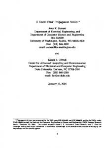
dsd = dsr + drd Fig. 1.
The schematic of a two-hop relay-aided system
978-1-4244-5637-6/10/$26.00 ©2010 IEEE
This full text paper was peer reviewed at the direction of IEEE Communications Society subject matter experts for publication in the IEEE Globecom 2010 proceedings.
Fig. 1 shows the basic schematic of a two-hop relay-aided system, which is used in our design. During the first cooperative transmission period the SN transmits a frame of coded symbols xs to both the RN and DN. Then the RN decodes the information and transmits a frame of coded symbols xr to the DN during the second cooperative transmission period. More specifically, during the first transmission period, the kth symbol received at DN may be written as: √ (1) ysd,k = Gsd hsd,k xs,k + nsd,k , where k ∈ {1, ...,N} and N is the number of symbols transmitted from the SN, while hsd,k denotes the quasi-static Rayleigh fading coefficient between the SN and the DN. Moreover, nsd,k represents the AWGN having a variance of N0 /2 per dimension. Similarly, the kth symbol received at the RN may be expressed as: √ ysr,k = Gsr hsr,k xs,k + nsr,k , (2) where hsr,k denotes the quasi-static Rayleigh fading coefficient of the link between the SN and the RN, while nsr,k represents the AWGN having a variance of N0 /2 per dimension. It is assumed that the number of symbols transmitted from the SN is the same as that from the RN. The kth symbol received during the second transmission period may, therefore, be formulated as: √ (3) yrd,k = Grd hrd,k xr,k + nrd,k , where hrd,k represents the quasi-static Rayleigh fading coefficient of the RN to DN link, while, nrd,k represents the AWGN having a variance of N0 /2 per dimension. The reduced-distance-related pathloss reduction (RDRPLR) of the SR link related to the SD link can be expressed as [18], [13]: � �n dsd . (4) Gsr = dsr Here, the pathloss exponent equals to n = 2, because a freespace Line-of-Slight (LOS) pathloss model is assumed. Similarly, the RDRPLR of the relay-to-destination (RD) link related to the SD link may be formulated as: � �2 dsd . (5) Grd = drd Naturally, the RDRPLR of the SD link related to itself is unity, yielding, Gsd = 1, where dsr represents the distance between the SN and RN, while drd is that of the RD link and dsd is that of the SD link. Moreover, for the sake of simplicity we assumed without loss of generality that the SN, the RN and the DN are positioned along a straight line. Therefore, we have:
the DN, where it is employed for mitigating the effects of error propagation. In this model, the RN’s location is fixed. Let qki denote the RNBER of the ith bit of the kth symbol, where we have i ∈ {1, ..., m} and m represents the number of coded bits per BICM symbol. For simplicity, we assume that the RN-BER is perfectly known at the DN, which may be accurately estimated based on the decoder’s soft output. It was shown in [11] that only a modest performance degradation is imposed, when a realistically estimated BER value is relied upon. Here, we introduced the sequence Δcik , which hosts a logical one to indicate the position of the decoding errors, where the probability of the decoding errors Δcik can be expressed as: � 1 − qki , if Δcik = 0 (7) P (Δcik ) = qki , if Δcik = 1. During the BICM-ID decoding iterations at the DN the extrinsic a pOsteriori probability P (cik ; O) of the original coded bits (cik ) and the error-indicator sequence Δcik [19] are interleaved independently, and then they are fed back to the input of the demapper as the probability of the a priori information, where again O refers to the extrinsic a pOsteriori information. Considering the RN-BER and the a posteriori probability P (cik ; O) of the BICM decoder’s output bits [19], the joint probability P (ˆ cik ; O) may be calculated as: ⎧ (1 − qki )P (cik = 0; O) + qki P (cik = 1; O) ⎪ ⎪ ⎨ , if cˆik = 0 P (ˆ cik ; O)= (8) i i i (1 − qk )P (ck = 1; O) + qk P (cik = 0; O) ⎪ ⎪ ⎩ i , if cˆk = 1, which may be used to generate the Log-Likelihood Ratio (LLR) [19] of cik . Considering P (cik = 1; O) as an example, we have [11], [19]: P (ci = 1; O) = P (cik = 1) ⎧ k √ � � m ⎨ −|yrd − Grd hrd xr |2
exp P (ˆ cik ; O) (1 − qki ) ⎩ N0 i j� = i c ˆk =1 ⎫ √ � �
m ⎬ 2 −|yrd − Grd hrd xr | + qki exp P (ˆ cik ; O) , ⎭ N0 i j�=i
c ˆk =0
Again, below we beneficially combine the CRDED [11], [12] and the RNSPA [13]–[15] techniques. The proposed algorithm and its analysis will be presented in the following subsections.
where j ∈ {1, ..., m}, j �= i. It is worth mentioning that the conventional BICM-ID decoder may be employed for the SD link without any modification, since this link is free from any RN-induced decoding errors. Although error propagation may be encountered at the DN, it is mitigated with the aid of the RN-BER estimator shown in Fig. 2, which can help the DN to correct the decoding errors produced at the RN with the aid of the side information that is generated from the information received from the SN via the direct link. Having considered the CRDED method, let us now briefly focus our attention on the RNSPA technique.
A. Correcting the Relay’s Decoding Errors at the Destination
B. RN Selection or Power Allocation
Practically, the RN may have decoding errors and if so, then the erroneous packets are transmitted from the RN to DN, which inevitably degrades the achievable end-to-end performance [11]. We denote the BER of the BICM coded bits at the RN as RN-BER. More specifically, the RN-BER is given by the BER of the BICM decoded bits at the RN, which can be estimated form the soft-metrics of the BICM decoder. Fig. 2 shows the schematic of the entire system, where the interleaver and de-interleaver are represented by π and π −1 , respectively. The estimated RN-BER has to be signalled to
When transmitting over quasi-static Rayleigh fading channels, the constant fading coefficient and the power of the AWGN determines the received Signal to Noise power Ratio (SNR) for each transmission frame. The estimated SNR can be used for choosing the optimum RN location. According to [15], the average SNR at the RN may be expressed as:
dsd = dsr + drd .
(6)
SN Rr,sr =
978-1-4244-5637-6/10/$26.00 ©2010 IEEE
E{Gsr }E{|hsr |2 }E{|xs,k |2 } , N0
(9)
This full text paper was peer reviewed at the direction of IEEE Communications Society subject matter experts for publication in the IEEE Globecom 2010 proceedings.
Source N ode u
BICM c Encoder
Destination N ode c� π
xs
BICM Mapper
Buffer_LLR_sd +
yrd
BICM Demapper
_
+
π −1
SISO
+
MAP _
π Relay N ode
BICM Demapper
Fig. 2.
P (ˆ cik ; O)
+ +
P (cik ; O)
Δcik SISO
π −1
MAP
Hard Decision
cˆ�
π
Relay_ber estimator
xr
The block diagram of the RN-BER-aided system
where xs,k is the kth symbol transmitted from the SN. For the sake of simplifying our analysis, we define the ’equivalent SNR’1 characterizing the SN to RN link as: SN Rt,sr =
E{|xs,k |2 } , N0
(10)
where we have E{|xs,k |2 } = 1. Hence, we arrive at: SN Rr,sr = SN Rt,sr Gsr |hsr |2
(11) 2
γr,sr = γt,sr + 10log10 (Gsr |hsr | )[dB],
the DN receives the data at a relatively low SNR, thus we have a poorer performance. By contrast, if the RN is closer to the DN, the situation is reversed. At a BER of 10−4 , there is an almost 5dB SNR difference between these two scenarios. As seen in Fig. 3, the performance curves of the RNSPA method are represented by the solid lines. Note that the BER curves of the RNSPA method decay faster than those of the CRDED method. The corresponding Frame Error Ratio (FER) performance is presented in Fig. 4.
(12)
-1
γr,rd − 10log10 (Grd |hrd | ) = γr,sr − 10log10 (Gsr |hsr | ) γr,rd −γr,sr Grd |hrd |2 10 = 10 . 2 Gsr |hsr |
(13)
Gsr = |hsr |
10
2 -2
10
5 2
If γr,sr is fixed to γr,sr min , the following relationship may be derived from Eqs. (14) and (15): (γr,sr min −γt,sr ) 10
-1
5
(14)
Based on Eqs. (4), (5) and (6), the relationship between Gsr and Grd may be expressed as: � �2 1 √ . (15) Grd = 1 − 1/ Gsr
−2
2
10
BER
2
Threshold(at RN-BER=10 ) with Perfect Relay -3 Threshold(at RN-BER=10 ) with Perfect Relay -6 Threshold(at RN-BER=10 ) with Perfect Relay Gsr=Grd=4 with Perfect Relay Gsr=3Grd with Perfect Relay Gsr=Grd/3 with Perfect Relay
5
where we have γr,sr = 10log10 (SN Rr,sr ) and γt,sr = 10log10 (SN Rt,sr ). Furthermore, we assume having the same transmit power at the SN and at the RN, which corresponds to equalpower-sharing between them. Hence, we have: 2
b_pccf-4.gle
1
.
(16)
-3
10
5 2 -4
10
-6
-4
-2
0
2
4
6
8
10 12 14 16 18
20 22 24 26 28 30
SNR(dB)
Fig. 3. BER versus SNR performance for perfect relay aided BICM-ID for transmission over quasi-static Rayleigh channels both for the CRDED and for the RNSPA method. The system’s schematic is portrayed in Fig. 2 and the simulation parameters are summarised in Table I.
Then, based on Eq. (15), Grd can be obtained. III. S IMULATION R ESULTS C. Analysis of both methods for perfect relaying In this sub-section, the performance of the CRDED and RNSPA methods is presented for the idealized perfect relaying scenario, where we have RN-BER = 0. Fig. 3 shows the BER performance of the perfect relaying scenario. The dotted lines represent the performance of the CRDED method in the following three scenarios: 1) the RN is half-way between the SN and DN, 2) the RN is closer to the SN and 3) the RN is closer to the DN. As seen in Fig. 3, if the RN is located close to the SN, Grd is relatively low, hence 1 We note that this definition does not represent a physically tangible or measurable quantity, since it relates the transmit power of the SN to the AWGN power encountered at the RN. Nonetheless, this convenient definition simplifies our discussions.
The performance of the proposed systems is characterized in this section using the simulation parameters of Table I. Firstly, the performance of the CRDED method recorded for RN-BER aided BICM-ID is characterized in Fig. 5, which illustrates the BER performance of the CRDED system for a fixed RN location. When the RN is half-way between the SN and the DN, there is an almost 7dB difference between the BER performance curve of the CRDED scheme exploiting the estimate of RN-BER and that operating without exploiting the knowledge of the RN-BER. Furthermore, encountering different RN locations results in a different performance. More specifically, the longer the SR link, the more substantially the BER performance of the CRDED technique improves, since the effects of the avalanche-like RN-induced error propagation become more
978-1-4244-5637-6/10/$26.00 ©2010 IEEE
This full text paper was peer reviewed at the direction of IEEE Communications Society subject matter experts for publication in the IEEE Globecom 2010 proceedings.
f_pccf-3.gle
1 -1
5
2
10
kc_lee_-4.gle
Threshold(at RN-BER=10 ) with Perfect Relay -3 Threshold(at RN-BER=10 ) with Perfect Relay -6 Threshold(at RN-BER=10 ) with Perfect Relay Gsr=Grd=4 with Perfect Relay Gsr=3Grd with Perfect Relay Gsr=Grd/3 with Perfect Relay
-1
1
Gsr=Grd=4;with RN-BER Gsr=Grd=4;without RN-BER Gsr=3Grd;with RN-BER Gsr=3Grd;without RN-BER Gsr=Grd/3;with RN-BER Gsr=Grd/3;without RN-BER
5 2
10
-1
5
FER
5
BER
2 2
-2
10
5
-2
10
2 5 -3
10
5
2
2
-3
10
-6
-4
-2
0
2
4
6
8
10 12 14 16 18
20 22 24 26 28 30
-4
10
SNR(dB)
-6
-4
-2
0
2
4
6
8
10 12 14 16 18
20 22 24 26 28 30
SNR(dB)
Fig. 4. FER versus SNR performance for perfect relay aided BICM-ID for transmission over quasi-static Rayleigh channels both for the CRDED and for the RNSPA method. The system’s schematic is portrayed in Fig. 2 and the simulation parameters are summarised in Table I. Coded Modulation Modulation Code Code Memory length Number of iterations Decoder Symbols per frame Number of frames Channel Pathloss
Threshold Corresponding AWGN BER
BICM-ID
Fig. 5. BER versus SNR performance for RN-BER aided BICM-ID for transmission over quasi-static Rayleigh channels for the CRDED method. It is worth noting that the differences in comparison to Fig. 3 are 1) the RN-BER instead of perfect relaying, 2) only the CRDED method is used.
QPSK R= 12 Convolutional 3
kc_lee_-3_fer.gle
1 5
8
2
Approximate Log-MAP [19] 1,200
Gsr = Grd Gsr = Grd = 4 4 (6.02dB) (6.02dB) 0.89 dB RN-BER = 10−1
10
-1
5
FER
10,000
Gsr=Grd=4;with RN-BER Gsr=Grd=4;without RN-BER Gsr=3Grd;with RN-BER Gsr=3Grd;without RN-BER Gsr=Grd/3;with RN-BER Gsr=Grd/3;without RN-BER
2
Quasi-static Rayleigh channel Gsr = Grd /3 Gsr = 3Grd Gsr = Grd = Gsr = Grd = 1.78 16 16 1.78 (2.50dB) (12.04dB) (12.04dB) (2.50dB) 5.35 dB 8.09 dB RN-BER = 10−3 RN-BER = 10−6
-2
10
5
2 -3
10
-6
-4
-2
0
2
4
6
8
TABLE I
10 12 14 16 18
20 22 24 26 28 30
SNR(dB)
S YSTEM PARAMETERS . Fig. 6. FER versus SNR performance for RN-BER aided BICM-ID for transmission over quasi-static Rayleigh channels for the CRDED method. It is worth noting that the differences in comparison to Fig. 4 are 1) the RN-BER instead of perfect relaying, 2) only the CRDED method is used. our_proposed_4.gle
1 5 2
10
-1
. .
-1
.
5
. .
-1
Threshold(at RN-BER=10 ) with RN-BER=10 -1 -1 Threshold(at RN-BER=10 ) without RN-BER=10 -3 -3 Threshold(at RN-BER=10 ) with RN-BER=10 -3 -3 Threshold(at RN-BER=10 ) without RN-BER=10 -6 -6 Threshold(at RN-BER=10 ) with RN-BER=10 -6 -6 Threshold(at RN-BER=10 ) without RN-BER=10
.
2
BER
catastrophic in the absence of the RN-BER knowledge, i.e. in the absence of the CRDED technique. For instance, the performance of the RN-BER aided scenario was improved by approximately 19dB in the case of Gsr = Grd /3. By contrast, we have a modest 2dB improvement with the aid of the CRDED scheme for Gsr = 3Grd . Therefore, the employment of the CRDED technique becomes more crucial, when the RN is closer to the DN. The corresponding FER performance shown in Fig. 6 exhibits similar trends. Let us now consider the performance of our proposed method in comparison to the RNSPA technique. Observe from Fig. 3 and Fig. 4 that when the SNR increases in the idealized perfect relaying scenario, the RNSPA method has a better performance than the CRDED since the latter is expected to have no benefits in the absence of errors. Hence the philosophy of our hybrid method is that we activate the RNSPA and CRDED modes of operation, depending on whether the SR channel’s SNR exceeds a threshold value, above which the RNSPA technique is activated. This is because in the presence of a sufficiently high SR SNR the RN-BER becomes low and hence we no longer have to exploit this RN-BER knowledge. Table I shows the threshold value γr,sr min expressed in dB, which is used for selecting a RN at a desired location or using the appropriate transmit power at the RN. This threshold directly corresponds to a
-2
.
10
5
.
2 -3
10
.
5 2 -4
10
-6
-4
-2
0
2
4
6
8
10 12 14 16 18
20 22 24 26 28 30
SNR(dB)
Fig. 7. BER versus SNR performance for RN-BER aided BICM-ID for transmission over quasi-static Rayleigh channels both for the RNSPA method and for the proposed hybrid method. The system’s schematic is portrayed in Fig. 2 and the simulation parameters are summarised in Table I. The RN-BER of 10−1 , 10−3 and 10−6 was exploited, respectively.
978-1-4244-5637-6/10/$26.00 ©2010 IEEE
This full text paper was peer reviewed at the direction of IEEE Communications Society subject matter experts for publication in the IEEE Globecom 2010 proceedings.
1
. .
5
our_proposed_fer.gle
.
-1
.
.
2
10
R EFERENCES
.
2
.
-2
10
5
.
2 -3
10
work, cooperative spatial multiplexing schemes will be considered, but we note that the proposed techniques are applicable to a broad class of DF-aided cooperative schemes.
.
-1
5
FER
-1
Threshold(at RN-BER=10 ) with RN-BER=10 -1 -1 Threshold(at RN-BER=10 ) without RN-BER=10 -3 -3 Threshold(at RN-BER=10 ) with RN-BER=10 -3 -3 Threshold(at RN-BER=10 ) without RN-BER=10 -6 -6 Threshold(at RN-BER=10 ) with RN-BER=10 -6 -6 Threshold(at RN-BER=10 ) without RN-BER=10
-6
-4
-2
0
2
4
6
8
10 12 14 16 18
20 22 24 26 28 30
SNR(dB)
Fig. 8. FER versus SNR performance for RN-BER aided BICM-ID for transmission over quasi-static Rayleigh channels both for the RNSPA method and for the proposed hybrid method. The system’s schematic is portrayed in Fig. 2 and the simulation parameters are summarised in Table I. The RN-BER of 10−1 , 10−3 and 10−6 was exploited, respectively.
specific RN-BER under the assumption of a quasi-static Rayleigh channel, which corresponds to an AWGN channel having a fadingdependent SNR. More specifically, the optimum relay location or the transmit power required at the RN can be chosen based on the optimum RDRPLR, which can be generated from the knowledge of the transmit power at the SN and that of the received power at the RN. The simulation results provided below will justify, why our proposed system is superior to both the CRDED and the RNSPA method. Fig. 7 and Fig. 8 illustrate the BER and FER performance of the proposed hybrid system, respectively. Observe in Fig. 7 that regardless, whether the RN-BER-knowledge is exploited or not, the achievable performance remains similar in the case of a low decoding error probability encountered at the RN. However, when the decoding error probability is high at the RN, the exploitation of the RN-BER becomes more crucial for the sake of limiting the RN-induced error propagation. For instance, as seen in Fig. 7, our proposed method achieves an approximately 12dB power reduction over the RNSPA method, when using a RN-BER threshold of 10−1 for activating the CRDED technique. More specifically, an SNR of almost 21dB is required for achieving a target BER of 10−4 by the RNSPA, which becomes about 9dB for our proposed technique, as indicated by the dotted-starred and by the continuous-triangle lines, respectively. It is worth noting that the FER seen in Fig. 8 is poor, when the RN-BER threshold used for activating the CRDED technique is set to 10−1 . In contrast to Fig. 4 and Fig. 6, the FER performance of the CRDED scheme approaches that of the perfect relaying situation, while the FER performance remains inferior in comparison to that of our proposed scheme. Since the CRDED method implicitly relies on having a fixed RN location, which is associated with a time-invariant RN-BER, its performance is expected to degrade in the presence of high RN velocity or low RN-BER signalling rates. It can also be observed in Fig. 8 that if the RN-BER is in excess of 10−1 , then the FER also becomes too high to be effectively reduced by the proposed system.
[1] L. Hanzo and O. Alamri and N. El-Hajjar and N. Wu, Near-Capacity Multi Functional MIMO Systems. John Wiley & Sons, Ltd, May 2009. [2] T. M. Cover and A. E. Gamal, “Capacity theorems for the relay channel,” IEEE Transaction on Information Theory, vol. 25, pp. 572–584, Sept 1979. [3] J. N. Laneman, “Cooperative diversity in wireless networks: algorithms and architectures,” PhD Dissertation, Massachusetts Institute of Technology, Aug 2002. [4] S. Sugiura, S. Chen, and L. Hanzo, “Cooperative differential spacetime spreading for the asynchronous relay aided cdma uplink using interference rejection spreading code,” IEEE Signal Processing Letters, vol. 17, pp. 117 –120, Feb. 2010. [5] L. Wang and L. Hanzo, “The resource-optimized differentially modulated hybrid af/df cooperative cellular uplink using multiple-symbol differential sphere detection,” IEEE Signal Processing Letters, vol. 16, pp. 965 –968, Nov. 2009. [6] H. Xiong, J. Xu, and P. Wang, “Frequency-domain equalization and diversity combining for demodulate-and-forward cooperative systems,” in IEEE International Conference on Acoustics, Speech and Signal Processing, pp. 3245 –3248, 31 April 2008. [7] Y. Li and B. Vucetic, “On the performance of a simple adaptive relaying protocol for wireless relay networks,” in IEEE Vehicular Technology Conference, pp. 2400 –2405, May 2008. [8] Y. Li, B. Vucetic, T. F. Wong, and M. Dohler, “Distributed turbo coding with soft information relaying in multihop relay networks,” IEEE Journal on Selected Areas in Communications, vol. 24, pp. 2040 –2050, Nov. 2006. [9] Y. Li and B. Vucetic, “Distributed turbo coding with soft information relaying in wireless sensor networks,” in The International Conference on Computer as a Tool, Nov. 2005. [10] F. A. Onat, A. Adinoyi, Y. Fan, H. Yanikomeroglu, and J. S. Thompson, “Optimum threshold for snr-based selective digital relaying schemes in cooperative wireless networks,” in IEEE Wireless Communications and Networking Conference, pp. 969 –974, March 2007. [11] K. Lee and L. Hanzo, “Iterative detection and decoding for hard-decision forwarding aided cooperative spatial multiplexing,” in IEEE ICC 2009, (Dresden, Germany), pp. 1–5, 14-18 June 2009. [12] K. Lee and L. Hanzo, “Mimo-assisted hard versus soft decoding-andforwarding for network coding aided relaying systems,” IEEE Transactions on Wireless Communications, vol. 8, pp. 376 –385, Jan. 2009. [13] S. X. Ng, Y. Li and L. Hanzo, “Distributed turbo trellis coded modulation for cooperative communications,” in IEEE ICC 2009, (Dresden, Germany), pp. 1–5, 14-18 June 2009. [14] S. X. Ng, Y. Wang and L. Hanzo, “Distributed Convolutional-Coded Differential Space-Time Block Coding for Cooperative Communications,” in IEEE Vehicular Technology Conference, (Taipei), Spring 2010. [15] S. X. Ng, C. Y. Qian, D. Liang and L. Hanzo, “Adaptive Turbo Trellis Coded Modulation Aided Distributed Space-Time Trellis Coding for Cooperative Communications,” in IEEE Vehicular Technology Conference, (Taipei), Spring 2010. [16] X. Li, J. A. Ritcey, “Trellis-Coded Modulation with Bit Interleaving and Iterative Decoding,” IEEE Journal on Selected Areas in Communications, vol. 17, pp. 715–724, April 1999. [17] X. Li and J. A. Ritcey, “Bit-interleaved coded modulation with iterative decoding using soft feedback,” IEE Electronics Letters, vol. 34, pp. 942– 943, May 1998. [18] H. Ochiai, P. Mitran, and V. Tarokh, “Design and analysis of collaborative diversity protocols for wireless sensor networks,” in IEEE Vehicular Technology Conference, pp. 4645 – 4649, Sept. 2004. [19] L. Hanzo, T. H. Liew, B. L. Yeap, Turbo Coding, Turbo Equalisation and Space-Time Coding for Transmission over Fading Channels. WileyIEEE Press, 2002.
IV. C ONCLUSIONS A hybrid technique of mitigating the effects of RN-induced error propagation was proposed, which takes into consideration both the RN location and the RN-BER for mitigating the error propagation. The results have demonstrated that this technique is particularly beneficial, when the BER at the RN is high, since transmit power reductions up to 19dB were attained at a BER of 10−4 . In our future
978-1-4244-5637-6/10/$26.00 ©2010 IEEE