MATEC Web of Conferences 161, 03016 (2018) https://doi.org/10.1051/matecconf/201816103016 13th International Scientific-Technical Conference on Electromechanics and Robotics “Zavalishin’s Readings” - 2018
Remote control library and GUI development for Russian crawler robot Servosila Engineer Ilya Mavrin1, Roman Lavrenov1,*, Mikhail Svinin2, Sergey Sorokin3 and Evgeni Magid1 1
Intelligent Robotics Department, Higher School of Information Technology and Information Systems, Kazan Federal University, Russia Robot Dynamics and Control Laboratory, College of Information Science and Engineering, Ritsumeikan University, Japan 3 Mechanical Engineering Department, Chuvash State University, Russia 2
Abstract. Recently a large variety of robots are available on the global market for a reasonable price. Often it turns out that even though a robot has a high-quality hardware and architecture, an original software of the robot may have a number of drawbacks or lacks some important features, which are required for a particular application of the robot. In such cases a user may decide to implement new libraries and functionalities using a provided by a manufacturer application programming interfaces as in most cases code of a commercial robot system is not an open-source. A number of our ongoing research projects concentrate on applications of various robots in urban search and rescue operations, and in most of these projects utilize Russian crawler robot Servosila Engineer. This paper describes the development of a new ROS-based control software and graphical user interface for Servosila Engineer robot.
1 Introduction Today robotic applications replace a human in numerous scenarios that range from social-oriented human-robot interaction [1] to dangerous for a human urban search and rescue scenarios [2]. Modern mobile robots serve in indoor and outdoor environments and require skillful autonomous navigation within unknown GPS-denied environments [3], efficiency in dealing with computa-tionnal complexity of simultaneous localization and mapping (SLAM) [4], aptitude of negotiation [5] and collaboration with other robots within a group [6] and other functionality. Crawler-type UGVs are typical for urban search and rescue (USAR) operations, especially in situations where such mission deals with dangerous environments and high risk for human rescuers. In our research, we employ Russian crawler robot Servosila Engineer as a USAR-oriented platform [7]. Original Servosila Engineer robot does not contain any operator oriented software. Customers can use only a client-server system to control the robot in a simple teleoperation mode that implies usage of 3D vision goggles (or single camera view on an operator screen) and joystick. Our goal within this research project is to create a robot control software for an operator, which does not need a joystick and the control could be performed via Robot Operating System (ROS) framework. Since a large variety of algorithms for path planning, localization, and SLAM are implemented in ROS, in order to apply them with our robot our new library is allowing to receive control commands from ROS as well and not only from the user interface [8]. *
The rest of this paper is structured as follows. Section 2 describes robot Servosila Engineer and its original API. Section 3 presents the developed software, including a remote control library, a user interface program and a ROS node. We conclude in Section 4.
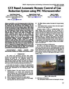
2 Servosila Engineer robot 2.1. Hardware and sensors A crawler-type mobile robot Servosila Engineer (Fig. 1) is designed and manufactured by Russian company "Servosila" for operating in difficult terrain conditions (e.g. pipeline and tunnel inspection or inspection underneath a static vehicle). The robot is equipped with radiation-hardened electronics and a sensors pack, which includes an optical zoom camera, a pair of stereo vision cameras, back camera and IMU. The robot is tooled with a headlight for operations in low illumination conditions and a manipulator for grasping, pushing or pulling potentially dangerous objects or opening doors with its gripper in teleoperated mode. In addition to a standard sensor package, we equipped the robot with an extra laser range finder Hokuyo UTM-30LX-EW [8]. 2.2 Original robot software for teleoperation and application programming interface The software provided with the robot consists of a server and a client. The server starts immediately after booting the robot, receives commands from the client program and sends back the robot telemetry to the client. The
Corresponding author: Roman Lavrenov,
[email protected]
© The Authors, published by EDP Sciences. This is an open access article distributed under the terms of the Creative Commons Attribution License 4.0 (http://creativecommons.org/licenses/by/4.0/).
MATEC Web of Conferences 161, 03016 (2018) https://doi.org/10.1051/matecconf/201816103016 13th International Scientific-Technical Conference on Electromechanics and Robotics “Zavalishin’s Readings” - 2018
client is an Operator Control Unit (OCU), which is installed on the user's computer and sends commands to the server. To control the robot, the client requires an XBox joystick that should be calibrated before each use. The client program displays an image from a single camera and the current schematic image of the robot in the corner of the window. The operator has an opportunity to switch between the four cameras of the robot and to select a particular camera to stream the data into client GUI window.
Fig. 1. Servosila Engineer robot (courtesy of the manufacturer). Table 1. Remote Control Packet. Field
Size
Type
Frame type ID
1 byte
uint8
Axis #0
2 bytes
int16
Axis #1
2 bytes
int16
…
…
…
Axis #15
2 bytes
int16
Button #0
1 byte
uint8
Button #1
1 byte
uint8
…
…
…
Button #15
1 byte
uint8
Video bit rate telemetry
8 bytes
double
Total size
Telemetry Packets (Table 2) with information about cameras and servo drives, where each motor provides information about its state, position, speed, electric current (in amperes), commands etc. (the details about motor data are presented in Table 3). This protocol has an opportunity to send video frames with delay from a single camera of the robot. While using the robot in teleoperated mode with the original software, we noted the following drawbacks of the protocol: • Strong dependency of the protocol on game controller. Thus, the protocol allows performing only those commands (both with the original GUI or any new GUI of an external developer) that are available for the game controller. • The protocol allows to send only speed values to the servo drives and control by position is implemented on OCU side. • The protocol does not allow checking the battery charging level. For this reason, an operator has to constantly check battery charging level by connecting an additional display to the embedded computer of the robot. • The protocol prevents a simultaneous rotation of the waist joint and chassis. Thus it is impossible to rotate the waist joint while robot is in motion and the robot has to stop first. • The protocol does not allow checking the headlight state. Thus an operator has to check visually (e.g., through one of the robot front cameras) whether the headlight is on or off. • The protocol does not allow gripper joint rotation. Due to these restrictions the protocol, our library could only emulate an interaction with the game controller. In order to implement all required for a comfortable teleoperation features, the protocol should be reviewed and the server side should be re-implemented, which is a part of our future work. Table 2. Telemetry Packet.
57 bytes
Five times per second the OCU sends Remote Control Packets (Table 1), which contain information about buttons and joysticks of Xbox 360 controller. On the other side onсe per second the robot sends to OCU
2
Field
Size
Type
Frame type ID
1 byte
uint8
Tick number
8 bytes
uint64
Number of motors
1 byte
uint8
Motor data #0
24 bytes
struct
Motor data #1
24 bytes
struct
…
…
…
Motor data #9
24 bytes
struct
Not used
25 bytes
-
Total size
275 bytes
MATEC Web of Conferences 161, 03016 (2018) https://doi.org/10.1051/matecconf/201816103016 13th International Scientific-Technical Conference on Electromechanics and Robotics “Zavalishin’s Readings” - 2018 Table 3. Motor data. Field
Size
Type
Device ID
1 byte
uint8
Device state
1 byte
uint8
Operation mode
1 byte
uint8
Position
4 bytes
uint32
Speed
2 bytes
int16
Electric current (in amperes)
2 bytes
int16
Status bits
2 bytes
int16
4 bytes
uint32
2 bytes
int16
2 bytes
int16
Position command Speed command Electric current command (in amperes)
controlling the robot via Wi-Fi (or radio communication). The commands are encapsulated by the developed by Servosila company remote control protocol (Table 1). The remote control library is implemented as a shared library (*.so file), which gives an opportunity to use the library with other applications. For example, pathfinding algorithms could be implemented for Servosila Engineer robot using API of the remote control library. The library consists of the following blocks (Fig. 3): • Structure RobotConfiguration contains information about the configuration of the robot, including a set of maximal velocities of the joints; • Class Robot is a wrap of the class Controller, which sends joint velocities from RobotConfiguration to Controller methods; • Class RobotController starts a thread for UDPClient and controls the robot by updating the required values in remote control packet; • Class RobotPositionController extends RobotController, so it can control particular joints by position control; • Struct RobotSI converts commands to SI System (International System of Units) in order to handle velocity values in m/s and rad/s; • Struct RobotPackets contains implementation of the packets from Servosila’s API protocol;
3 Software development The original GUI provides basic functionality and an operator could control robot in real time only using Xbox 360 game controller. For this reason, we decided to develop a new GUI and remote control library with an extended functionality, which should provide robot control from the ROS framework and assure a more comfortable teleoperation process. Our new software consists of three parts: a remote control library, a graphical user interface (GUI), and a ROS node program. The structure of robot control environment with description of remote control library, GUI for an operator and a ROS node are illustrated with in Figure 2.
• Class UDPClient provides data sending service from the client to the server (on the robot);
Fig. 2. The schemе of our software. Fig. 3. The remote control library scheme.
3.1 Remote control library Remote control library is a mediator between GUI and ROS node on one side and the robot (through its API) on the other. It is used for sending commands to the robot and receiving information from the cameras and the servo drives. The library has a set of API functions, which are used for
3
The library is built with qmake and g++ using Qt framework [9]. The library works in its own thread and connects to GUI and our ROS node (that is currently in development) using Qt signals and slots mechanism. While this solution allowed a quick development of the robot control environment, is has a number of drawbacks.
MATEC Web of Conferences 161, 03016 (2018) https://doi.org/10.1051/matecconf/201816103016 13th International Scientific-Technical Conference on Electromechanics and Robotics “Zavalishin’s Readings” - 2018
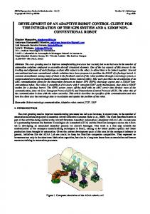
First of all, every application, which plans to use the library should include Qt libraries to support signals and slots mechanism. Therefore, the application should include Qt libraries in its binary (which dramatically increases size of binary) or dynamically link Qt libraries (which sets constraints on OCU). For this reason, as a part of our future work we plan to rewrite library from scratch without Qt using pure C++, without any libraries, frameworks and other significant dependencies. UDP client in library encapsulates static object with the structure of Remote Control Packet and Qt implementation of UDP socket. UDP client runs in its own thread and sends the packet five times a second. Each packet could be constructed via operations with GUI or commands from ROS node. Telemetry packets bring useful information to OCU. A packet contains information about each motor, including motor state, motor shaft position and speed, electric current, speed command etc. (Table 2). Motor shaft position information is used for position control, but the chassis motor drives do not have position telemetry information. This issue may be resulted by absence of encoders in these motors or by the original API. This way, the only available approach for travelled distance calculation with robot odometry turns out to be multiplying travel velocity in m/s by travel time is seconds, which is significantly less precise with regard to encoders usage. The protocol stores values of each servo speed as integers in the range [-32768, 32767], which correlates the velocities with positions of control sticks of Xbox 360 game controller. The remote control library should be able to accept velocity values in m/s, which is necessary both for a user convenience and for ROS node program. In order to identify mapping between abstract API commands and real-world motion with reverse engineering approach, we performed a set of experiments for linear and rotational motions of the robot. The main idea of the experiments is to convert API numbers to real-world measure units, which requires to explore tracks rotation velocity depending on API commands sent to robot. The correlation between these values should be expressed as a ratio between API commands numbers and real-world velocity in meters per second. The experiments were performed as follows: 1. Install the robot in way that nothing influences tracks rotation velocity (including friction, Fig.4); 2. Measure length of the tracks l; 3. Send constant velocity commands to the robot; 4. Pick a relatively large number N of full rotations of the tracks; 5. Measure time duration t which is required for full rotation of the tracks N times; 6. Compute real-world velocity in meters per second with the equation: vr = l*N/t
(1)
In order to neglect any external influence on tracks rotation velocity, the robot was installed on two blocks in the way that its tracks do not touch the blocks or any other surface during their movement (Fig. 4). The robot base and a track were marked with external markers for
4
rotations count. Every time the two markers match, the number of rotations is incremented by one. The track length l is 1.15 m. We set number N to 40, which is large enough to eliminate random friction influence between tracks and driving wheels.
Fig. 4. The robot fixed position during the experiments.
Based on the results of the experiments, we concluded that the integer values, which are sent to the robot, are linearly proportional to the velocity of linear movement and rotation. We calculated these two coefficients by converting integer values to the SI system using least squares method. The linear motion value was lv = 71553.837 and the rotation motion value was lr = 25171.216. In order to obtain the velocity in m/s and rad/s we divided the integer values by these constants, and the resulting values were incorporated into RobotSI class. 3.2 Graphical User Interface program Graphical User Interface (GUI) is an application, which can be used to control the robot in real time. An operator could set speed (for all joints) and position (for several joints) values. These values are sent to the Remote control library using QT signals and slots, which in turn sends these values to the robot. The GUI consists of two active windows. The velocity control window (Fig. 5) contains elements of the robot control, a connect button, a button for switching to the maximal velocity window and a checkbox to enable\disable the robot torch. In addition, there are switches for flippers and gripper control. In the maximal velocity window (Fig. 6) an operator could set a maximal velocity for each joint using an appropriate slider or a textbox, which will set the upper limit for a corresponding velocity slider and hotkeys. GUI offers a variety of ways to control the robot: • Using keyboard hotkeys; • Using sliders or textboxes for velocity control of each joint; • Using textboxes for position values (only for several joints); An operator could use keyboard to control the robot in real time.
MATEC Web of Conferences 161, 03016 (2018) https://doi.org/10.1051/matecconf/201816103016 13th International Scientific-Technical Conference on Electromechanics and Robotics “Zavalishin’s Readings” - 2018 Table 4. Keyboard layout.
Fig. 5. Velocity control window.
Key
Movement
W
Drive forward
S
Reverse
A
Rotate left
D
Rotate right
Q
Waist rotate left
E
Waist rotate right
Y
Shoulder up
H
Shoulder down
F
Flippers up
R
Flippers down
G
Grippers close
T
Grippers open
U
Elbow up
J
Elbow down
Space
Emergency stop
3.2.3. Position Values The joints, which support position control, include the elbow, the neck, the shoulder, the waist (these joints have the corresponding labels in GUI). An operator can use position values for these joints by setting values in the textboxes of the joint position control window (Fig. 7). The joints will automatically move into a required position after the operator presses button «Accept». The contents of telemetry packets that arrive from the robot are displayed in the same window. Unfortunately, due to drawbacks of the existing remote control protocol of the robot, it is impossible to send position values directly to the robot.
Fig. 6. Maximal velocity window.
3.2.1 Keyboard controls In this mode an operator should hold the key to move the particular joint (Table 4). When he/she releases the key, the servo immediately stops. This mode allows to hold multiple keys simultaneously. The implementation uses Qt keypress events. 3.2.2 Sliders An operator could use sliders for controlling all joints of the robot. Once he/she sets the slider, the joint starts moving. A user can set velocities in textboxes and joints will move after he/she presses the button «Accept». At any time, the operator could press an emergency stop button «StopAll» (or press hotkey «Space»), which immediately stops all servo drives.
5
Fig. 7. Joint position control window.
We implemented position values handler on OCU side. The handler finds motor shaft`s position values in telemetry packets for each required motor and compares
MATEC Web of Conferences 161, 03016 (2018) https://doi.org/10.1051/matecconf/201816103016 13th International Scientific-Technical Conference on Electromechanics and Robotics “Zavalishin’s Readings” - 2018
these values with required position values for each motor respectively. It calculates the difference between the values and sets motor velocities, positive or negative, depending on current and required motor shaft positions. Currently its implementation is rather simple: motor speed doesn`t depend on the difference between required and current values. 3.3 ROS node program Since Servosila Engineer robot uses some of the existing in ROS algorithms for autonomous localization, mapping and path mapping, a ROS node is required. In ROS framework nodes generate motion commands in \geometry_msgs\Twist format, which contains linear (for all axes) and angular velocities (for all axes) being measured in meters and radians respectively. Therefore, a velocity conversion function, which is a part of our remote control library, is required. Our remote control library is included into ROS node, which sends ROS commands from ROS node \move_base to the robot via Wi-Fi connection. In order to do that, library was statically compiled and its headers were included into ROS node source file. ROS node is a console program. The node workflow, which runs in a loop, works as follows: 1) Wait for messages on the specified topic (e.g.\cmd_vel\). 2) When a new message arrives, it is split in two parts: linear and angular. If the linear (angular) part exceeds or equal to 0.2 m/s (0.2 rad/s) then, it is sent to the robot. If the linear (angular) part is positive, but does not exceed 0.2 m/s (0.2 rad/s) then, the value of 0.2 m/s (0.2 rad/s) is sent to the robot. The values of 0.2 m/s (0.2 rad/s) were selected experimentally as these are the lowest velocities that are required by robot servos to start moving. Before the node shuts down, it sends zeros to angular and linear velocities in order to stop the robot and prevent any uncontrolled motion.
4 Conclusions and future work Often robot original software lacks some important features, which are required by a user for a particular application. These forces a user to implement new functionalities using a provided by a manufacturer API. A number of our ongoing research projects utilize Russian crawler robot Servosila Engineer, and this paper describes the development of a new ROS-based control software and graphical user interface for Servosila Engineer robot. With our new software and GUI a user can operate the robot without using a joystick, which was the only control possibility with the original GUI. Moreover, because our software is based on robot operating system ROS, it broadens practical applications functionality due to capability of incorporating different existing and open-source ROS-based standard useful algorithms and functions into the robot control system. Currently, we further improve the GUI by allowing to simultaneously displaying data from all four robot cameras in real time instead of the original single camera
6
data display that allows only a sequential switching between the cameras. As a part of our future work, we plan to add new features into the GUI, including position control for all joints and visual displaying of a current robot configuration with a 3D schematic model. Next, we will add several automatic functions including a pilot advisory system that considers static and dynamic balance of the robot while selecting a suitable path [10]. This work was partially supported by the Russian Foundation for Basic Research (RFBR) and Ministry of Science Technology & Space State of Israel (joint project ID 15-5706010). Part of the work was performed according to the Russian Government Program of Competitive Growth of Kazan Federal University.
References 1.
V.Y. Budkov, M.V. Prischepa, A.L. Ronzhin, A.A. Karpov, Int. Congress Ultra Modern Telecommunications, 485–488 (2010) 2. A. Birk, S. Schwertfeger, and K. Pathak, IEEE Wireless Communications, 16.1, 6–13 (2009) 3. K. Yakovlev, V. Khithov, M. Loginov, A. Petrov, IEEE Int. Conf. on Intelligent Systems, Springer Int. Publishing, 49–56 (2015) 4. A. Buyval, I. Afanasyev, E. Magid, Int. Conf. on Machine Vision, 103411K (2016) 5. B. Li, S. Ma, T. Liu, J. Liu, IEEE Int. Symp. on Safety, Security and Rescue Robotics, 53–57 (2008). 6. N. Michael et al. Journal of Field Robotics, 832–841 (2012) 7. M. Sokolov, R. Lavrenov, A. Gabdullin, I. Afanasyev, E. Magid, Int. Conf. on Control, Mechatronics and Automation, 61–65 (2016) 8. N. Alishev, R. Lavrenov, Y. Gerasimov, Int. Conf. on Artificial Life and Robotics, 204–207 (2018) 9. Qt framework, Available at: https://www.qt.io/ 10. E. Magid, T. Tsubouchi, E. Koyanagi, T. Yoshida, Int. Conf. on Intelligent Robots and Systems, 349–356 (2010)