Repetitive Scheme Plugged-in Parallel with Deadbeat Controller for VFD Fed by Cascaded Multilevel Inverter M. Trabelsi, L. Ben-Brahim
A. Kawamura
College of Engineering, Electrical Department Qatar University Doha, Qatar
[email protected]
Faculty of Engineering, Intelligent Systems Engineering Yokohama National University Yokohama, Japan
[email protected]
T. Yokoyama
T. Yoshino, R. Kurosawa
Department of Robot and Mechatronics Tokyo Denki University Tokyo, Japan
[email protected]
Power Electronics Division TMEIC Tokyo, Japan
[email protected]
Abstract— This paper proposes an experimental Real Time Digital Feedback Controller (RTDFBC) combined with a Repetitive technique to control a Variable Frequency Drive (VFD) fed by a cascaded Multi-Level Inverter (MLI). The proposed controller is Deadbeat type compensating for noncyclical disturbances while the repetitive controller compensates for cyclical fluctuations (Dead-time effect, DC voltage imbalance effect) by generating proper compensating d-q voltages. This digital control is characterized by a very fast transient response, low switching losses, and a proper compensation for load disturbances and cyclical fluctuations. Theoretical analysis, simulation, and experimental results are described in this paper.
I.
INTRODUCTION
Several industrial applications have begun to require medium voltage high power devices in recent years. This has led to the development of multilevel inverter topologies. Thus, many types of multilevel inverters were proposed such as the Neutral Point Clamped (NPC) inverter which is now a standard topology in the industry with its 3-level version. However, the clamping diodes and the balance of the dc-link capacitors [1] issues present some problems for a higher number of levels. An alternative structure is the Multi-cell topology. The most important topologies are Cascaded HBridge (CHB) [2] and the Flying Capacitors Inverter (FCI) [2][3]. These Multi-cell topologies are easily scalable and highly reliable as they permit the operation even with some faulty
cells [4]. Another concern is the switching losses of semiconductor devices, which increase with the switching frequency and the number of switching devices. For high power induction motor drive, the switching frequency of controlled PWM inverters is reduced to keep the switching losses low, which results in large current ripples, which in turn, produces torque ripples [5]. Furthermore, most industrial systems perform tasks that are repetitive in nature. Such industrial systems include motors, steel mills, and PWM converters/inverters, which are required to carry out repetitive tasks with precision and robustness to disturbances and repeatability imperfections [6]. The issue of rejecting periodic disturbances arises in various applications especially in systems dealing with rotating machinery. Unlike conventional controllers such as PI controller which cannot cancel these repetitive effects, the Repetitive Control (RC) technique is usually used for such as applications. In 1981, the concept of repetitive control was originally developed [7]. The initial motivations were the tracking of periodic reference inputs in a motion control application. Later, RC approaches have been used in robotic applications [8] and for inverters control. In [9], a repetitive controller has been used for a constant frequency constant voltage inverter with an LC output filter. Commonly, RC techniques are used in continuous processes for tracking or rejecting periodic disturbance signals. In most cases, the period of the disturbance signal is known. However, the Internal Model Principle (IMP) proposed in [10] is the theoretical foundation of RC.
This work is supported by Qatar National Research Fund (member of Qatar Foundation) through the NPRP grant #08-548-2-223.
978-1-4799-0336-8/13/$31.00 ©2013 IEEE
1070
This paper proposes a real time deadbeat control theory for current regulation to minimize the current and torque ripples. Furthermore, in order to reject periodic disturbances, a Repetitive Controller (RC) is proposed and plugged-in parallel with the deadbeat controller. The RC has capability of learning through iterations and is feed-forward control technique based on tracking error. It compensates the limitations of feedback control design in the deficient knowledge of modeling errors and disturbances. During the control, the compensation method uses the actual current errors to produce the proper output, which is superposed with the deadbeat current output. The new combined controller will achieve higher dynamic performance and reduced cyclical disturbance effects.
A. Modelling The dynamics of IM in the synchronously rotating d-q frame is given by: (1) where:
;
1
This paper is organized as follows: section II describes the proposed system; section III presents simulation results; section IV validates the simulation results through experimental implementation; section V concludes the paper. II.
PROPOSED SYSTEM
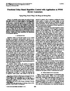
Fig. 1 shows the 9-cell three-phase CHB inverter feeding an Induction Motor (IM). The input DC links of all cells are obtained from multiple secondary windings which are shifted from each other by 20° using a phase-shift transformer. For the proper operation of the CHB inverter, a balanced three-phase voltage reference Vabc* are input to the SPWM scheme. The new controller will exhibit a very fast response while eliminating the cyclical disturbance fluctuations due to periodic disturbances.
;
1
0 0
1
0
0
0
1
0
;
0 0 ;
The IM parameters denotations are given in TABLE I. .
Figure 1. Circuit of the proposed system
1071
;
TABLE I.
As standard, for inverter applications, time delay must be inserted in switching signals to prevent a short circuit in the dc link. For the proposed CHB inverter, the upper and lower switches of the same leg operate in a complementary manner. Although, this time delay guarantees safe operation of the inverter, it causes distortion in the output currents which deviate from the reference values. Since this is repeated for every switching operation, its effect may become significant. As the deadbeat controller cannot compensate for cyclical disturbances such as the dead-time, the conventional Dead-time compensation method as well as a Repetitive strategy were applied.
INDUCTION MOTOR PARAMETERS DENOTATION
Symbol
Description
Ids, Iqs
d and q axis stator currents
Vds, Vqs
d and q axis stator voltages
Φdr, Φqr
d and q axis rotor fluxes
Ls, Lr
Stator and rotor inductances
Lm
Mutual inductance
Rs, Rr
Stator and rotor resistances
ws
Electrical synchronous speed (rad/s)
wr
Electrical rotor speed (rad/s)
wsl
Electrical slip speed (rad/s)
C. Conventional Dead-time Compensation In the conventional method, the dead-time effect is modeled by the average deviation voltage given by [11]: ,
∆ B. Deadbeat Control Algorithm Assuming that the inverter is for relatively high power application, a 2 kHz sampling frequency fs is chosen. The sampled-data model is derived from (1) with the assumption that the rotor speed is constant during a sampling period Ts as follows: 1
(2)
1
;
T
;
(5)
where Td is the dead-time, Tc is the carrier period, E is the dc link voltage and Ij is the line current. It’s worth noting that the average deviation voltage depends on the line current polarity. With the conventional method, the average deviation voltage will be added to the reference voltages in order to compensate this deviation. The reference phase voltage will be given by: ∆
(6)
In this paper, the d and q axis compensating voltages depend on the polarity of the reference currents. The calculated voltages are included in the deadbeat control law as shown below:
where: ;
,
1
T
(7)
1 with the reference Using (2) and replacing 1 to be tracked, the deadbeat control law is given as follows:
where V represents the compensating reference voltages V vector defined by: V V
1
D. Repetetive Controller In literature, periodic signals with a known period T can be generated by a time delay block with a positive feedback loop [12]-[13]. With these systems, it is possible to track a periodic reference or reject periodic disturbances with the same fundamental frequency. A controller including this model is well known as a repetitive controller.
(3)
This deadbeat control law is defined as state feedback output deadbeat control. It forces the output currents to be exactly equal to the reference signal at each sampling instant. It is worth noting that the values of , and , which depends on the actual motor speed and plant parameters, are calculated from the actual stator current and the actual rotor flux . Thus, the actual rotor fluxes must be provided at every sampling time in order to calculate the stator voltage output. As these fluxes cannot be measured, they will be estimated from the measured stator currents and the electrical slip speed as follows:
In this paper, a repetitive controller is plugged in parallel with the RTDFBC controller to create a proper dead-time compensating voltages (works as periodic signal generator). Using the motor currents, the repetitive controller forces the actual currents to track the reference currents and to achieve a zero steady state error in response to step command by generating the compensation voltages VdRc and VqRc. The RC and the RTDFBC are both implemented in the synchronously rotating reference frame as shown in Figure 2.
(4)
1072
Compensating voltages(V)
The upper part of Figure 7 shows the steady state torque response with reduced ripples when the lower part shows the steady state waveform of the q axis current. It’s worth to note that this current matches also the reference at each sampling time. Finally, Figure 8 shows the reverse speed operation.
Figure 2. Repetitive controller scheme
Vdcc Vqcc
5
0
-5 0.3
0.305
0.31
0.315
0.32
0.325 0.33 Time (s)
0.335
0.34
0.345
0.35
SIMULATION RESULTS
Digital simulations were carried out to verify the proposed methods. The IM is controlled through the CHB Multilevel using RC or conventional Dead-time compensation method plugged in parallel with the deadbeat controller. The induction motor is modeled in the α-β stationary reference frame. The motor parameters used for simulations are listed in TABLE II. Figure 3 shows the compensating voltage references generated by the conventional Dead-time compensation method. As shown in this figure, the three-phase currents are still little distorted and the dead-time effect is not well compensated. Thus, Figure 4 shows the effect of the RC application on the threephase currents. Notice that the RC compensates progressively the dead-time effect and the distortion is little by little removed. As a result, Figure 5 shows the compensated three-phase currents illustrating the deadbeat response. The three-phase 7-level output voltages are shown in Figure 6.
Stator currents(A)
20 iaref
10
ia ibref
0
ib ic ref
-10 -20 0.3
ic 0.305
0.31
0.315
0.32
0.325 0.33 Time (s)
0.335
0.34
0.345
0.35
Figure 3. Conventional dead-time compensation method; upper: compensating reference voltages in the synchronous rotating frame (dq);lower: actual compensated stator currents (A 50 iaref
40
ia ibref
30
Stator Currents (A)
III.
10
20
ib ic ref
10
ic
0 -10 -20 -30
TABLE II.
SIMULATION PARAMETERS
-40
Simulation parameters Description
Value
Unit
fs
Sampling frequency
2
kHz
Pn
Nominal Power
1.1
kW
V
Line-line voltage
200
V
f
Operating frequency
50
Hz
nr
Rated speed
1000
p
Number of poles
6
Lm
Mutual inductance
27.1
mH
Rs
Stator resistance
0.407
Ω
Ls
Stator inductance
28.7
mH
Rr
Rotor resistance
0.4445
Ω
Lr
Rotor inductance
29.1
mH
J
Inertia
0.0179
Kgm2
-50 0.2
0.25
0.3
0.35
0.4
0.45 Time(s)
0.5
0.55
0.6
0.65
0.7
Figure 4. Proposed repetitive controller;left: depicted currents before RC setting-up; right: depicted currents when RC set-up 30 iaref ia ibref
20
Rpm Stator currents(A)
Symbol
ib ic ref
10
ic 0
-10
-20
-30 0.3
0.305
0.31
0.315
0.32
0.325 0.33 Time (s)
0.335
0.34
0.345
Figure 5. Three-phase currents with Deadbeat response
1073
0.35
IV.
150 Va Vb Vc
100
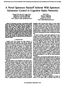
The experiment study of the proposed control laws was conducted with equipment composed of a 9-cell CHB inverter feeding an Induction Motor (Figure 9). The input dc links of all cells are obtained from multiple secondary windings which are shifted from each other by 20° using a phase-shift transformer.
Phase Voltages(V)
50
0
The proposed control algorithms were implemented in C language and computations are performed by an eZdsp F28335 stand-alone card through the TMS320F28335 digital signal controller (DSC).
-50
-100
-150 0.3
0.305
0.31
0.315
0.32
0.325 0.33 Time (s)
0.335
0.34
0.345
0.35
Figure 6. Three-phase output voltages
2 Torque(Nm)
EXPERIMENTAL RESULTS
The experimental prototype specification are given in TABLE III.
TL Tem
1
For the proper operation of the CHB inverter, a balanced three-phase voltage reference Vabc* are input to the SPWM scheme. The generated voltage references were compared with a multi-carrier using the Phase Shift PWM (PSPWM) technique based on an FPGA controller board. Many tests were made to verify the proposed techniques.
0 -1 -2 0.3
Inverter Rack 0.305
0.31
0.315
0.32
0.325 0.33 Time(s)
0.335
0.34
0.345
0.35
(9-cell CHB inverter)
q-axis Current(A)
2 Iqref
1
Iq
Phase Shift Transformer
0 -1 -2 0.3
0.305
0.31
0.315
0.32
0.325 0.33 Time(s)
0.335
0.34
0.345
Controller Board
0.35
Motor Bench
Figure 7. Upper: Electromagnetic torque; lower: q-axis current
30 iaref ia ibref
Output currents(A)
20
ib ic ref
10
ic 0
-10
-20
-30 0.7
0.75
0.8
0.85
0.9
0.95 Time (s)
1
1.05
1.1
1.15
Yokogawa Oscilloscope
1.2
Figure 9. Experimental Power Set
Figure 8. Reverse speed operation
1074
TABLE III.
EXPERIMENTAL SET PARAMETERS
Multilevel CHB Inverter Specifications Symbol
Description
Value
Unit
Fs
Switching frequency
9
kHz
P
Output Power
5
kW
f
Operating frequency
50
Hz
Dead-time
5
µs
Tdead
Dead-time effect
Induction Motor Parameters Pn
Rated Power
2.2
kW
V
Line-line voltage (Rms)
200
V
nr
Rated speed
1500
Rpm
p
Number of poles
4
Lm
Mutual inductance
40
mH
Rs
Stator resistance
0.673
Ω
Ls
Stator inductance
41.76
mH
Rr
Rotor resistance
0.548
Ω
Lr
Rotor inductance
41.43
mH
J
Inertia
0.009
Kgm2
Figure 11. Dead-time effect on the experimental output currents
The upper part of Figure 10 shows the experimental three-phase currents. In its lower part, this figure shows the line-line three-phase output voltages of the Multilevel CHB inverter. Notice that this test was made under the nominal speed (1500Rpm). Figure 11 shows the three-phase currents biased by the dead-time effect (effect magnified at the zero crossing instants) when Figure 12 shows the dead-time compensation and its outcome on the output current. Finally, Figure 13 shows the three-phase current waveforms during the reverse speed operation (from -1500 Rpm to 1500 Rpm).
Figure 10. Experimental multilevel CHB inverter outputs; upper: threephase currents;lower:three-phase output voltages
Figure 12. Dead-time compensation
Figure 13. Reverse speed operation
1075
V.
CONCLUSIONS
A proposed method for cyclical disturbances (e.g. deadtime effect) compensation based on Repetitive controller plugged in parallel with a Deadbeat controller is described and compared to the conventional Dead-time compensation method in this paper. The simulation was carried out, for 9cell cascaded inverter feeding an Induction Motor. The elimination of the dead-time effect in the multilevel CHB inverter was achieved and the simulation has shown that the output current waveforms were improved when using the proposed RC method. Theoretical analyses were confirmed by simulation and experimental implementation using a 5kW 9-cell CHB inverter prototype.
[2]
[3]
[4]
[6]
[7]
[8]
[9]
REFERENCES [1]
[5]
L. Ben-Brahim, “A Discontinuous PWM Method for Balancing the Neutral Point Voltage in Three-Level Inverter-Fed Variable Frequency Drives (VFDs)”, IEEE Transactions on Energy Conversion, Vol. 23, No. 4, pp. 1057-1063, 2008. P. Lezana, J. Rodriguez, “Mixed multi-cell cascaded multilevel inverter”, IEEE Industrial Electronics, ISIE 2007, pp. 509-514, Vigo, June 4-7, 2007. M. Trabelsi, “Modélisation et Commande des Systèmes Physiques à Topologie Variable”, Editions Universitaires Européennes, ISBN: 978-613-1-55446-9, January 2011. J. Rodriguez, P. Hammond, J. Pontt, R. Musalem, P. Lezana, M. J. Escobar, “Operation of a medium-voltage drive under faulty
[10] [11] [12]
[13]
1076
conditions”, IEEE Transactions on Industrial Electronics, vol. 52, no. 4, pp. 1080–1085, Aug 2005. A. Bendre, G. Venkataramanan, “Neutral current ripple minimization in a three-level rectifier”, IEEE Transaction on Industry Applications , vol. 42, no. 2, pp. 582–590, 2006. L. Cuiyan, Z. Dongchun, Z. Xiang, “A survey of Repetitive Control”, IEEE/RSJ International Conference on Intelligent Robots and Systems, RSJ’04, Japan, 2004. T. Inoue, M. Nakano, S. Iwai, “High accuracy control of servomechanism for repeated contouring”, 10th Annual Symposium on Incremental Motion Control Systems and Devices, pp. 258–292, 1981. S. Hara, T. Omata, and M. Nakano, “Synthesis of repetitive control systems and its application,” 24th IEEE Conference on Decision and Control, vol. 24, pp. 1387–1392, Dec. 1985. K. Zhou and D. Wang, “Digital repetitive learning controller for three-phase CVCF PWM inverter,” IEEE Transactions on Industrial Electronics, vol. 48, no. 4, pp. 820–830, Aug 2001. B.A. Francis, W.M. Wonham, “Internal model principle for linearmultivariable regulators”, Appl. Math. Optim. 2,170–194, 1975. L. Ben-Brahim, “The analysis and compensation of dead-time effects in three phase PWM inverters”, IEEE IECON’98, pp.792–797, 1998. S. Hara, Y. Yamamoto, T. Omata and M. Nakano, “Repetitive control system: A new type servo system for periodic exogenous signals”, IEEE Trans. Automatic Control, v. 33, pp. 659-667, Jul. 1988. M.-C. Tsai, G. Anwar and M. Tomizuka, “Discrete time repetitive control for robot manipulators”, IEEE International Conference on Robotic and Automation, pp. 1341-1346., 1988.