across the set of similar products that a software company provides. A. Schnieders et al. explores the idea of apply- ing (SPL) techniques to BDD in an approach ...
Representing Runtime Variability in Business-Driven Development Systems∗ Ildefonso Montero, Joaquín Peña, Antonio Ruiz-Cortés Departamento de Lenguajes y Sistemas Informáticos Av. Reina Mercedes s/n, 41012 Seville (Spain) University of Seville {monteroperez, joaquinp, aruiz}@us.es
Abstract Business-Driven Development(BDD) is a research field that provides techniques and mechanisms for designing software systems starting from the business processes of the companies. Companies are in continuous evolution to adapt to market changes, thus, current process engineers redesign the processes every time that is needed using ad hoc techniques. This situation motivates that these changes, called runtime variability, must be managed. Some authors have used Software Product Lines (SPL) ideas to manage it. Current approaches for documenting runtime variability in SPL and BDD, proposes different model representations. Unfortunately, we have determined that the expressiveness level in BDD is not adequate and SPL solutions needs for adaptation to BDD context for describing under which circumstances a business evolves. In this paper, we present a model for representing runtime variability in BDD systems. The main contributions of this proposal are: (i) it presents the enough expressiveness level for representing runtime variability; and (ii) process engineers can represent and understand under which events a business evolves and how is managed this evolution, which is not present in current approaches. We call this approach Product Evolution Model (PEM).
1
Introduction
Business-Driven Development (BDD) is a research field that provides techniques and mechanisms for designing software systems starting from the business processes of the companies. Nowadays, BDD systems supports most of the activities of a company due to it improves their daily work ∗ This work has been partially supported by the European Commission (FEDER) and Spanish Government under CICYT project Web-Factories (TIN2006-00472) and under a scholarship from the Education and Universities Spanish Government Secretariat given to the author Ildefonso Montero.
and their strategic management. Thus, Information Technology (IT) infrastructure must evolve to adapt companies to the continuous evolution of markets. Currently this evolution is supported by ad hoc techniques to maximize the level or reuse from one version to another, redesign the processes every time that is needed. It motivates that runtime variability support in business processes is needed. Software Product Lines (SPL) systematizes the reuse across the set of similar products that a software company provides. A. Schnieders et al. explores the idea of applying (SPL) techniques to BDD in an approach called Process Family Engineering (PFE) [7]. Basically, PFE follows the SPL philosophy for managing the variability of the business process of an unique business, thus, managing only one software system. That is to say, each product in PFE represents an evolution of the process (at runtime). However, although PFE may be the solution to manage the evolution of the business process of a company, proposed models, feature models, are not expressive enough for documenting this evolution because are devoted to design time. In addition, runtime variability has been also analyzed in SPL, as J. Bosch et al. in feature models [4], or H. Gomaa et al. in software components-based architectures design [3][2]. Although these proposals presents valuable solutions for other contexts, they need for integration and extensions in the BDD context. The main motivation of this paper is that analyzed approaches does not provide the expressiveness level needed for representing runtime variability. In addition, current approaches does not take into account that process engineers must document, in their business process definitions, a clear description about under which circumstances some processes are in use and which do not at runtime; and how these processes are performed in a business evolution (a parallel collaboration between processes, a sequence, etc). Our approach integrates quoted approaches for modeling runtime variability in BDD systems oriented providing a set of artifacts able to represent properly runtime evolutions and trigger events that implies these changes into the
business process of a company. For that purpose, it provides an abstract formal description of business evolutions and a proposal for representing it based on Business Process Model Notation (BPMN) [1]. The main benefits of our approach are that it provides the enough expressiveness level for representing runtime variability in BDD systems, and that events or conditions that fires business evolutions can be observed and analyzed by process engineers. This paper is structured as follows: Section 2 presents the background information needed to understand our approach; Section 3 presents our approach for modeling runtime variability in BDD systems, called Product Evolution Model; Section 4 presents the related work and motivation of our work; and finally, in the last section, we draw the main conclusions of our approach.
2 2.1
Feature Model
Process Evolution Model Business B
SVF t
Business B B
...
Business
CF + SVF t
CF Processes
t+1
F (t, SVFt)
...
F (t, SVFt)
Instant t + 1
VF Processes
CF + SVF t + 1
SVF t+1
...
B
Legend
t + k; k>0
Business
: Core Processes CF : Variable Processes VF
Processes
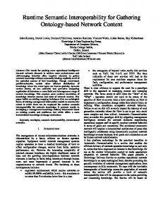
Figure 1.a. Formal Description
Figure 1.b. Graphical Notation
Figure 1. Product Evolution Model approach defining an evolution of a business by F∆ function in t and t + 1.
Preliminaries Software Product Lines and Feature Models
Software Product Lines (SPL) systematizes the reuse across the set of similar products that a software company produces. The main goal of SPL is to obtain a reduction of the overall development costs and times for the products derived from the product line. In SPL a product is composed of a set of common features and a set of variable features. Common features appears in all product and variable features appears under demand of consumer’s products. Observing a certain product of an SPL, although it is described as a set of fixed features, some features can be in use in a certain moment and some not. This is called runtime variability. Feature Models (FM) are one of the most used artifacts for modeling variability, that is, specifying which features are common and which are variable. A FM represents all possible products in an SPL in terms of features. There exists several notations of FM as FODA [5] or J. Bosch [4]. A FM establishes a parental relationship between each feature, as shown in Figure 2, that can be: (i) Mandatory: if a child feature node is defined as mandatory, it must be included in every product that contains the parent; (ii) Optional: if a child feature node is defined as optional, it can be included or not when its father feature appears in a product; (iii) Alternative: if the relationship between a set of children nodes and their father is defined as alternative, only one of the children features could be included in every father feature products; and (iv) Or: if the relationship between a set of children nodes and their father is defined as or, one or more of them could be included in every father feature products. In addition to the parental relations between features, a FM can also contain cross-tree constraints between couples of features. These are: (i) Requires: If a feature A requires a
Formal Definition Instant t
feature B, the inclusion of A in a product implies the inclusion of B in such product; and (ii) Excludes: if a feature A excludes a feature B, both features can not be part of the same product.
2.2
Process Family Engineering
Process Family Engineering (PFE) [7] explores the idea of applying SPL philosophy for managing the evolution of BDD systems. PFE uses FM for representing the set of processes contained into a business, and BPMN for representing an specific process. In PFE we obtain only one software system that evolves at runtime, where the features are processes. Every process evolution represents a product that contains a subset of features, but the PFE system contains all the features. The main difference between SPL and PFE is that SPL provides a set of different products that shares common features, and PFE provides only one product, which represents a business, that evolves at runtime, and each possible configuration of this business is managed as a product that contains a subset of features (processes) enabled at a certain moment of the execution. Thus, given that FM are devoted to design time, the main problem of PFE is that this approach uses FM for managing runtime properties.
3
Product Evolution Model
In this section, we present an abstract formal description of Product Evolution Model and a proposal for representing it by means of an extension of BPMN using stereotypes. We also include a case study to illustrate our approach.
: Core Features CF
Fast-Food Restaurant
F∆ (t, SV Ft ) = SV Ft+1 ∈ V F
: Variable Features VF
Serve
Serve Normal Mandatory Optional Alternative relation relation relation
A
A
B
B
A
Or relation
A B2
B
A
Requires constraint
Establishment
A
B1
B1
Delivery
Auto
B2 B
Cafeteria Birthday´s party
Excludes constraint
Figure 2. Case Study: Fast Food Restaurant Fast-food restaurant
F ( t, ServeInCafeteria) SVF t+1 :
Serve in . . . Cafeteria and Establishment
F ( t + 1, ) SVF t+2 : ServeInAuto
Serve in Establishment
10:00 am ( t +1 )
11:20 am ( t +2 )
Cafeteria Service close at 10:00 am
Serve in Auto and ... Establishment
A client has arrived to Auto-Service
Figure 3. Fast-food restaurant Product Evolution Model BPMN Compositions
3.1
•SV F t 6= SV F t+1
Cook
Services
Serve Fast
Formal Description
Let B be a business. Each business can be defined as a set of processes (denoted with P ). Thus, B can be defined as follows: B = {P1 , P2 , ..., Pk }; k > 0; 1 ≤ i ≤ n Let CF be the set of common processes or features and let VF be the set of variable features, thus B is defined formally as a tuple containing all the CF and a subset of V F denoted as SV F : B = (CF, SV F ∈ V F ) As shown before, in PFE approach, each configuration of the set of processes enabled at certain moment represents a product. Thus, we can say that the CF of a B are always enabled at runtime, but the set of processes in V F is not fixed at runtime. Thus, we can set up a product line that takes into account this runtime variability. For formalizing these concepts we should redefine each business B as: B = (CF, SV F ∈ V F, F∆ : : t, {F eature × ... × F eature} 7→ 7→ {F eature × ... × F eature}) where F∆ is a function that given an instant t transform the set of SV Ft into the new set of variable features of the following time instant t+1, that is to say SV Ft+1 , formally:
Figure 1.a sketches a graphical representation of F∆ , where it is represented the transformation of SV Ft into SV Ft+1 . In an instant t there exists an specific set of SV Ft for business B that evolves in instant t + 1 to another different set SV Ft+1 .
3.2
Graphical Notation
As shown previously, a business that evolves can be represented by B = (CF, SV F ∈ V F, F∆ ). where the evolution is defined by the F∆ function in t. In PFE feature models are used to represent which features are variable and which do not. From this, a the set of common features (CF ) and (V F ) can be obtained [6]. Thus, CF and V F can be represented by means of a feature model. However, the feature model cannot establish the order of apparition of business processes, represented as F∆ , due to feature models are not devoted for temporal conditions or variables (t) [2]. For that purpose, we have to add a new model with a graphical notation that represents F∆ , the Product Evolution Model, which is defined by means of a BPMN state machine where each state represents a product and each evolution between two or more states, is represented by means of a transition that is an application of F∆ function. Figure 1.b shows how is defined an evolution of a business by F∆ function in t and t + 1 by means of BPMN. It represents an specific graphical notation for the formal description of our approach, but other notations can be applied. To show our approach we use a fast-food restaurant case study. Figure 2 depicts a simplified set of processes contained into a fast-food restaurant which Serve Normal, Serve Fast and Serve in Establishment are CF and all the rest of the processes are V F . In Figure 3 we present the PEM of our case study. Each process contains a BPMN state chart that represents how all the processes are performed. It defines the configuration of the business at runtime and sketches that in every runtime instant t there exists a different SV F selected that represents an evolution. In this example, on a time instant t the restaurant open its cafeteria service, thus, there exists in parallel two different processes: Serve in Cafeteria and CF (Serve in Establishment Normal/Fast). When the restaurant close its cafeteria service on time instant t + 1, 10:00 am, F∆ function is applied and an evolution is done to another state composed only by CF . After that the restaurant opens its Auto-Service, due to a client has arrived with his car, and a new evolution is applied for t + 2 time instant.
Feature Firefox
External Feature
Plugin
or specialization runtime
Flash
Java
Website Debugger
Figure 4. J. Bosch approach State machine view
Component model view
Feature model view
> >
Activate
MicrowaveControl Active
Reactivate Passivate [Waiting for Neighbor Response]
Passivate [Processing Transaction]
Waiting for Acknowledgement
Microwave System ...
...
...
> >
ControlSystem
BeeperComponent
...
Passivating
Transaction Started Transaction Transaction Ended * Aborted
Transaction Ended **
Beeper
Passive
>
Passive Acknowledgement from all Neighbors
Inactive
IBeeper {feature = Beeper} + initialize() + beep()
* At least one neighbor active ** All neighbors passive
Figure 5. Gomaa approach
4
any approach that provides an appropriate modeling support for runtime variability for BDD systems. Bosch approach represents a first step toward enabling runtime variability support for feature models, but unfortunately it it does not associate any additional information about when or how some features can be in use at runtime and some not (it does not take into account F∆ ). Gomaa proposal is a solution to manage the evolution of software systems based on architectural reconfiguration patterns and SPL ideas, but it is focused to software components architectures context instead of BDD systems and FM does not represent how enable/disable features at runtime (F∆ is partially supported but it is not associated with any FM). Process engineers must see processes that are added or removed from their business design instead of software components reconfigurations at a lower and concrete software development level. Finally Schnieders proposal, PFE, uses FM for managing runtime evolution, which are devoted to design time.
Related work and motivation
As shown in Section 2, FM are one of the most used artifacts for modeling variability. Unfortunately, as shown by [2], FM are devoted to design variability, and not for runtime variability. To the best of our knowledge, there exists two approaches for documenting runtime variability. On the one hand, J. Bosch et al. [4] introduces an extension of FM for representing runtime variability. Bosch’s notation syntax is slightly different from FODA’s or FORM’s notation. It introduces a new kind of feature, called external feature, represented by dashed rectangles, for representing features that varies at runtime. Figure 4 depicts an example of a feature model in this notation that represents Firefox plugin support. Time instants and conditions or constraints to enable/disable Website Debugger plugin, as for example concrete website domains, can not be represented by FM. On the other hand, H. Gomaa et al. [3][2] propose a set of models for representing runtime variability based on evolutionary reconfigurable software architectures. The different versions of an evolutionary system are considered a software product line, where each version of the system is a SPL member and the reconfiguration is defined by an state machine that, for each component, represents the steps that has to be performed to evolve from a normal operation state to an inactive state. Once inactive, the component can be removed and replaced with a different version of the component. Figure 5 depicts trigger events in the state machine. Given this state of art for runtime variability in BDD and SPL, the motivation of this paper is that there not exists
5
Conclusions
We propose a new approach for modeling runtime variability in BDD systems, called Product Evolution Model. The main advantages over current solutions are that our proposal provides to process engineers an enough expressive set of models which are able to represent and understand: (i) under which trigger events or business policies a business evolves and (ii) how is managed this evolution.
References [1] BPMI. Business process modeling notation BPMN version 1.0 - may 3, 2004. OMG. [2] H. Gomaa. Feature dependent coordination and adaptation of component-based software architectures. In WCAT ’07: Proceedings of the 4th Workshop on Coordination and Adaptation Techniques for Software Entities, 2007. [3] H. Gomaa and M. Hussein. Model-based software design and adaptation. In ICSEW ’07: Proceedings of the 29th International Conference on Software Engineering Workshops, 2007. [4] J. V. Gurp, J. Bosch, and M. Svahnberg. On the notion of variability in software product lines. In WICSA ’01: Proceedings of the Working IEEE/IFIP Conference on Software Architecture (WICSA’01), 2001. [5] K. Kang, S. Cohen, J. hess, W. Novak, and S. Peterson. Feature-oriented domain analysis FODA feasibility study. CMU/SEI-90-TR-21. Technical report, Carnegie Mellon University. SEI, 1990. [6] K. Pohl, G. Böckle, and F. van der Linden. Software Product Line Engineering: Foundations, Principles and Techniques. Springer, September 2005. [7] A. Schnieders and F. Puhlmann. Variability mechanisms in e-business process families. In Proceedings of BIS ’06: Business Information Systems, 2006.