Research Article A Quick Negative Selection Algorithm for One-Class
Recommend Documents
feasibility of combining the NS algorithm with classification algorithms [11]; in this case, the ..... S. Forrest, A. Perelson, L. Allen, and R. Cherukuri. Self-nonself ...
May 13, 2013 - detectors, time complexity, and false alarm rate. 1. Introduction ... the same coverage rate with less detectors compared with sphere ones.
Selection Algorithm and Clonal Selection Algorithm offer many features that can be exploited to address anomaly detection problem. Detectors in NSA aim to ...
In business, it is well known for service providers that attracting new .... Decision trees (DT) were applied and compared with ANN and logistic regression. ..... mining techniques in customer relationship management: a .... Software Engineering.
Apr 16, 2013 - To the best of our knowledge, this is the first time to introduce ... The optimization problem of web service selection. Antibody ..... One method is to directly design a powerful search engine to search in the whole solution space.
risk companies [28], learning [29], intrusion detection in 'wi-fi' networks [30] etc. Although AIS encompasses several different types of algorithms, the most ...
numbers (upto hundreds) of samples which leads to a problem of âcurse of ..... PSO is originally attributed to Kennedy, Eberhart and Shi [24,25] and was first ...
Aug 21, 2014 - Information Processing, N. Pal, N. Kasabov, R. Mudi, S. Pal, and. S. Parui, Eds., vol. 3316 of Lecture Notes in Computer Science, pp.
Apr 11, 2018 - Shock and Vibration. Volume 2018, Article ID 4654659, ... can be treated as a combination of the body part and the tail part. Under the POT ...
Recommended by Vitor Nascimento. Chirp-rate, as a ... estimator based on the cubic phase function (CPF) [10â. 14]. ... not depend on nT, the CPF was proposed for the chirp-rate ...... data-driven window length,â IEEE Transactions on Signal.
Journal of Medical Imaging and. Health Informatics. Vol. 4, 384â394, 2014. Firefly Algorithm for Optimization of Scaling. Factors During Embedding of Manifold.
Nov 14, 2016 - In the four-step braiding process, shown in Figure 2, yarn carriers are arranged in an array. In the first step, line 1 (top. Hindawi Publishing ...
Jun 24, 2013 - route planning algorithm is proposed to calculate the route with the shortest ... A-star (A. â. ) [9] algorithms are usually used to plan routes in.
Jul 10, 2011 - to the DIs sent by n pairs of sensing nodes A and B. Here, m ..... AM. 4:00. PM. 8:00. PM. 12:00. PM. Output. Figure 7: The traffic data quality ...
Random Freight Demands in Synchromodal Transportation. Yan Xu, Chengxuan Cao, Bin .... by allocating container capacity appropriately in planning horizon.
May 5, 2014 - This paper introduces modified firefly algorithm (FA) for the CCMV ... Firefly algorithm is one of the latest, very successful swarm intelligence ...
Sep 1, 2014 - algorithm which is based on the quadrilateral location unit by using .... ranging of model-based experience has shown that an offline .... fluctuated up and down between the constant real RSSI value, ..... on the other hand, the lower s
Received 18 December 2017; Revised 11 May 2018; Accepted 10 June 2018; Published 6 August 2018. Academic Editor: JoËao Cardoso. Copyright ...... Proceedings of the 20th IEEE International Symposium on Field- .... EMBC 2016, pp.
Received 1 August 2012; Revised 29 October 2012; Accepted 4 November 2012 ..... gsat. ( gsat(âαTF,x2(k â 1),âTF),x2(k â 1). âxâ. 2 (k), gsat(TF,x2(k â 1),αTF). ).
Mar 8, 2018 - The algorithm is divided into seven steps, which are described below. ..... rithm in line (7), the obtained equations are stored in. EQ ELLIPSES ...
Jun 4, 2017 - and effective solution based on genetic algorithms to solve this classical problem. We report results ... of graph theory, specifically the study of dominating sets had addressed this ... those queens including the square dominated by t
Sep 28, 2014 - problem in e-commerce logistics system, we formulate a closed-loop location-inventory problem model considering returned merchandise to ...
Apr 9, 2017 - Outlier detection is an important data mining task, whose target is to find the ... overcome the drawback above, some model-free approaches.
May 30, 2013 - A Robust Algorithm for Optimisation and Customisation of Fractal Dimensions of Time Series Modified by Nonlinearly. Scaling Their Time ...
Research Article A Quick Negative Selection Algorithm for One-Class
Jun 12, 2017 - Negative selection algorithm (NSA) is an important kind of the one-class classification model, but it is limited in the big data era due to its low ...
Hindawi Mathematical Problems in Engineering Volume 2017, Article ID 3956415, 7 pages https://doi.org/10.1155/2017/3956415
Research Article A Quick Negative Selection Algorithm for One-Class Classification in Big Data Era Fangdong Zhu,1 Wen Chen,1,2 Hanli Yang,3 Tao Li,1,2 Tao Yang,1 and Fan Zhang1,4 1
College of Computer Science, Sichuan University, Chengdu 610065, China College of Cybersecurity, Sichuan University, Chengdu 610065, China 3 Chongqing University of Technology, Chongqing 400054, China 4 Chengdu University of Information Technology, Chengdu 610225, China 2
1. Introduction NSA was proposed by Forrest et al. in 1994 [1], which generates immune detectors based on the “Random-Discard” model. Initially, massive immature detectors are randomly generated, and then the ones covering the self-areas are discarded. Gonz´alez et al. presented the real-valued negative selection algorithm (RNSA) in 2003 [2], in which the detectors and antigens are studied in the real-value space. Ji and Dasgupta proposed V-Detector algorithm [3, 4]. It turns the fixed-length detectors in RNSA into the variable-sized detectors to enlarge the detection areas. In 2015, Cui et al. developed BIORV-NSA [5]. In their work, the self-radius can be variable and the detectors, which are recognized by other mature detectors, are replaced by new ones to eliminate the “detection holds.” In big data era, the low efficiency of NSA becomes an important challenge, which largely limits its applications. In this paper, we design a new NSA based on Voronoi diagrams, named VorNSA. In the VorNSA, a restrained Voronoi diagram is constructed based on the whole training set in the first
step. Then, two types of detectors are generated in the specific location of the Voronoi diagram separately. In order to accelerate the test stage of NSA, in particular for large scale dataset, a new testing strategy VorNSA/MR (VorNSA with MapReduce) is proposed. Unlike the testing stage of classic NSAs, data are divided into small groups and calculated to generate the labels separately in Map stage. Then the final labels can be obtained after merging and sorting in the Reduce stage. The contributions of this work can be summarized as follows. (1) Based on Voronoi diagrams, the optimal position of detectors is calculated directly rather than in a stochastic way. Therefore, the time consumption wasted on excessive invalid detectors is avoided. (2) In the Map/Reduce framework, data are partitioned into several small parts by VorNSA/MR and can be processed in parallel to enhance the self/non-selfdiscrimination efficiency. The rest of the paper is organized as follows. In Section 2, we describe the definitions of VorNSA. The original contribution of the paper is presented in Section 3. Experimental results on synthetic datasets and real-world datasets are
2
Mathematical Problems in Engineering
shown and discussed in Section 4. Conclusions appear in Section 5.
1.2 1
2. Basic Definition of VorNSA VorNSA is designed based on Voronoi, which is derived from computation geometry to search the nearest neighbors, and it has been widely utilized in the fields of life sciences [6], material sciences [7], and mobile navigation [8]. The basic definitions are listed as follows. Definition 1 (site). Site is a set of 𝑛 distinct points in the feature space. In VorNSA, all the training samples are defined as site points: 𝑆 = {𝑆1 , 𝑆2 , . . . , 𝑆𝑛 }. Definition 2 (Voronoi diagram). Vor(𝑆) divides the feature space into 𝑛 unoverlapped cells based on the given site set 𝑆, and each cell ](𝑆𝑖 ) only contains one site 𝑆𝑖 in 𝑆, such that any point 𝑞 in ](𝑆𝑖 ) satisfies dist(𝑞, 𝑆𝑖 ) < dist(𝑞, 𝑆𝑗 ) ∀𝑆𝑗 ∈ 𝑆, 𝑗 ≠ 𝑖, and dist( ) can be any distance metrics. Definition 3 (cell). All the cells construct a mathematic partition of the feature space, and the cell corresponding to site 𝑆𝑖 is denoted by ](𝑆𝑖 ). Definition 4 (largest empty circle). The largest circle with center 𝑝, which does not contain any site in 𝑆, is denoted by 𝐶𝑆 (𝑝). Theorem 5. A point 𝑝 is a vertex of Vor(𝑆) iff 𝐶𝑆 (𝑝) contains at least three sites on its boundary [9]. Definition 6 (I-detector). ⟨𝑐, 𝑟⟩, where 𝑐 is the detector position in the feature space, and 𝑟 is the detector radius, satisfies that 𝑐 corresponds to one vertex of the Voronoi diagram. Theorem 7. Given 𝑝 is the center of an I-detector, there are at least three sites located on the boundary of 𝐶𝑆 (𝑝), and these sites are the nearest neighbors of each other. Proof. According to Definitions 2 and 6, it can be inferred that the center of the I-detector p is an intersection of three or more cells. Suppose that 𝑝 is intersected by three cells ](𝑆𝑖 ), ](𝑆𝑗 ), ](𝑆𝑘 ), while the sites of these cells are 𝑆𝑖 , 𝑆𝑗 , 𝑆𝑘 . According to Definition 4 and Theorem 5, there is a largest empty circle 𝐶𝑆 (𝑝) that does not contain any site of 𝑆, and 𝑆𝑖 , 𝑆𝑗 , 𝑆𝑘 are located on its boundary. So 𝑆𝑖 , 𝑆𝑗 , and 𝑆𝑘 are the nearest sites of 𝑝 among the site sets 𝑆. Theorem 8. The bisector between sites 𝑆𝑖 and 𝑆𝑗 defines an edge of Vor(𝑆) iff there is a point 𝑞 on the bisector such that 𝐶𝑆 (𝑞) contains both 𝑆𝑖 and 𝑆𝑗 on its boundary with no other site [9]. Definition 9 (II-detector). ⟨𝑐, 𝑟⟩, where 𝑐 is the detector position in the feature space, and 𝑟 is the detector radius, satisfies that 𝑐 corresponds to the junction of the edges of Vor(𝑆) and the unit hypercube [0, 1]𝑑 .
S1
S3
0.8
S7
T
0.6
S2
S8
P V(S8 )
y 0.4
S5
S4 V(S4 )
S6
S10 V(S10 )
0.2 Q
S9
0 −0.2 −0.2
0
0.2
0.4
0.6
0.8
1
1.2
x
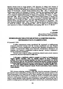
Figure 1: The red cross is the site. The blue line is the Voronoi diagram. The circle is the largest empty circle.
Theorem 10. Given 𝑞 is the center of II-detector, there are two sites located on the boundary of 𝐶𝑆 (𝑝), and these sites are the nearest neighbors of each other. Proof. According to Definitions 2 and 9, it can be inferred that the center of II-detector 𝑞 is an intersection of two cells. Suppose that 𝑞 is intersected by two cells ](𝑆𝑖 ), ](𝑆𝑗 ), while the sites of these cells are 𝑆𝑖 , 𝑆𝑗 . According to Definition 4 and Theorem 8, there is a largest empty circle 𝐶𝑆 (𝑞) that does not contain any site of 𝑆, and 𝑆𝑖 , 𝑆𝑗 are located on its boundary. So 𝑆𝑖 and 𝑆𝑗 are the nearest sites of 𝑞 among the site sets 𝑆. As an example in Figure 1, there are 10 sites 𝑆1 –𝑆10 in set 𝑆, and the space is divided into 10 cells ](𝑆1 )–](𝑆10 ) by the Voronoi diagram Vor(𝑆). The green circle is 𝐶𝑆 (𝑃), and three sites (𝑆2 , 𝑆8 , 𝑆10 ) are located on its boundary. The red circle is 𝐶𝑆 (𝑄), and two sites (𝑆8 , 𝑆10 ) are located on the boundary. The purple circle is 𝐶𝑆 (𝑇), and two sites (𝑆2 , 𝑆8 ) are located on the boundary. 𝑃 is the center of I-detector, while 𝑄 and 𝑇 are the centers of II-detector.
3. The Details of VorNSA 3.1. The Detector Generation Process of VorNSA 3.1.1. Space Partition Stage. First of all, all the training data are normalized to [0, 1]𝑑 feature space, where 𝑑 is the data dimension. The normalized training set is denoted by 𝑆. Secondly, a bounded Voronoi diagram Vor(𝑆) is constructed based on 𝑆, to divide the unit feature space [0, 1]𝑑 into 𝑛 cells, where 𝑛 = |𝑆|. Finally, the set 𝑉𝑆 = {⟨Vet(𝑆𝑖 ), 𝑆𝑖 ⟩ | 𝑖 = 1, . . . , 𝑛}, where Vet(𝑆𝑖 ), 𝑆𝑖 are the vertex and site in a cell ](𝑆𝑖 ), can be constructed. 3.1.2. I-Detector Generation Stage. According to Definition 6 and Theorem 7, the center of I-detector 𝑝 is designated by the
Mathematical Problems in Engineering
3
Input: Training set 𝑆, Self radius 𝑅𝑆 , Minimum detector radius 𝛿 Output: Detector set 𝐷 (1) normalize 𝑆 into [0, 1]𝑑 (2) construct voronoi diagram Vor(𝑆) by sites 𝑆 (3) get all cells ](𝑆𝑖 ) in Vor(𝑆) (4) construct 𝑉𝑆 = {⟨Vet(𝑆𝑖 ), 𝑆𝑖 ⟩ | 𝑖 = 1, . . . , 𝑛} by ](𝑆𝑖 ) (5) foreach ⟨Vet(𝑆𝑖 ), 𝑆𝑖 ⟩ in 𝑉𝑆 (6) if Vet(𝑆𝑖 ) has three or more same values in 𝑉𝑆 (7) then 𝑉𝑆1 = 𝑉𝑆1 ∪ ⟨Vet(𝑆𝑖 ), 𝑆𝑖 ⟩ (8) foreach ⟨Vet(𝑆𝑗 ), 𝑆𝑗 ⟩ in 𝑉𝑆1 (9) compute the detector radius 𝑅𝑃 using Eq. (1) (10) if 𝑅𝑃 > 𝛿 then 𝐷I = 𝐷I ∪ ⟨Vet(𝑆𝑗 ), 𝑅𝑃 ⟩ (11) foreach ⟨Vet(𝑆𝑖 ), 𝑆𝑖 ⟩ in 𝑉𝑆 (12) if Vet(𝑆𝑖 ) has two same values in 𝑉𝑆 (13) then 𝑉𝑆2 = 𝑉𝑆2 ∪ ⟨Vet(𝑆𝑖 ), 𝑆𝑖 ⟩ (14) foreach ⟨Vet(𝑆𝑘 ), 𝑆𝑘 ⟩ in 𝑉𝑆2 (15) compute the detector radius 𝑅𝑄 using Eq. (2) (16) if 𝑅𝑄 > 𝛿 then 𝐷II = 𝐷II ∪ ⟨𝑄𝑖 , 𝑅𝑄𝑖 ⟩ (17) return 𝐷 = 𝐷I ∪ 𝐷II Algorithm 1: VorNSA (𝑆, 𝑅𝑆 , 𝛿).
intersection of three or more cells, and the sites located in the cells are the nearest neighbors of each other. So a new set 𝑉𝑆1 = {⟨Vet(𝑆𝑗 ), 𝑆𝑗 ⟩|𝑗 = 1 ⋅ ⋅ ⋅ }, where Vet(𝑆𝑗 ) is the position of I-detector and 𝑆𝑗 is the nearest sites, can be obtained by Vet(𝑆𝑗 ) = {𝑥 | 𝑥 = Vet(𝑆𝑝 ) ∩ Vet(𝑆𝑞 ) ∩ Vet(𝑆𝑡 ), 𝑝 ≠ 𝑞 ≠ 𝑡}, where Vet(𝑆𝑝 ), Vet(𝑆𝑞 ), and Vet(𝑆𝑡 ) are the vertex sets of cell. Then, generating a mature detector is just through self-tolerating with 𝑆𝑗 . According to the principle of selftolerance, the radius of I-detector can be calculated with 𝑅𝑃 = dist (Vet (𝑆𝑗 ) , 𝑆𝑗 ) − 𝑅𝑆 ,
(1)
where 𝑅𝑃 is the radius of I-detector, Vet(𝑆𝑗 ) is the center of I-detector, 𝑆𝑗 is the nearest sites, and 𝑅𝑆 is the radius of selfantigens. Furthermore, a threshold 𝛿 of detector radius is introduced in case of overfitting: If the detector radius 𝑅𝑃 is less than 𝛿, the detector will be discarded. Otherwise, it will mature. 3.1.3. II-Detector Generation Stage. The main difference between the I-detector and the II-detector is the location of detector centers. According to Definition 9 and Theorem 10, the position of II-detector 𝑞 is located on the junction of two cells and the unit hypercube. The sites in the two cells are the nearest neighbors of each other. So a new set 𝑉𝑆2 = {⟨Vet(𝑆𝑘 ), 𝑆𝑘 ⟩ | 𝑘 = 1 ⋅ ⋅ ⋅ }, where Vet(𝑆𝑘 ) is the position of II-detector and 𝑆𝑘 is the nearest sites, can be obtained by Vet(𝑆𝑘 ) = {𝑥 | 𝑥 = Vet(𝑆𝑝 ) ∩ Vet(𝑆𝑞 ), 𝑝 ≠ 𝑞}, where Vet(𝑆𝑝 ) and Vet(𝑆𝑞 ) are the vertex sets of cell. Similarly, the radius of II-detector can be computed by (2), and a threshold 𝛿 of detector radius is introduced in case of overfitting. 𝑅𝑄 = dist (Vet (𝑆𝑘 ) , 𝑆𝑘 ) − 𝑅𝑆 ,
(2)
where 𝑅𝑄 is the radius of II-detector, Vet(𝑆𝑘 ) is the position of II-detector and 𝑆𝑘 is the nearest sites, and 𝑅𝑆 is the radius of self-antigens. Details of the VorNSA can be found in Algorithm 1. 3.2. The Immune Detection Process of VorNSA under Map/Reduce Framework. In the testing stage of traditional NSAs, each piece of data has to be compared with all the detectors to label its classification. This strategy is too time-consuming to be applied in big data era due to its low efficiency. In order to enhance the efficiency in testing stage, an immune detection process of VorNSA under Map/Reduce framework (VorNSA/MR) is proposed. Map/Reduce is a parallel computation framework, which splits the sample set into a group of small datasets and handles them on many cluster nodes simultaneously. Details of VorNSA/MR (Figure 2) are mainly divided into two parts: Map stage and Reduce stage. First of all, the testing datasets are split into 𝑛 parts by VorNSA/MR. In the Map stage, each cluster node selects a part of split data to compute the distance with matured detectors. If any distance is less than the detection radius, the testing sample is labeled with the non-self-antigens; otherwise it is labeled with the selfantigens. Then cluster nodes put results to the intermediate value. The Reducer receives the intermediate values, sorts them, and merges them into the final results. The implements of Map and Reduce stage can be found in Algorithms 2 and 3. 3.3. Theoretical Analysis Theorem 11. The time complexity of VorNSA is (𝑁𝑆 log 𝑁𝑆 + 𝑁𝑆 ⌈𝑑/2⌉ + |𝐷|), where 𝑁𝑆 is the size of training dataset, 𝑑 is the dimension of training dataset, and |𝐷| is the size of detectors.
4
Mathematical Problems in Engineering
Input: Detector set D, Split data T Output: Intermediate Value IV (1) foreach 𝑇𝑖 in 𝑇 (2) foreach 𝐷𝑘 in 𝐷 (3) Compute the Euclidean distance dist(𝑇𝑖 , 𝐷𝑘 ) between 𝑇𝑖 and 𝐷𝑘 (4) if 𝐷𝑘 .𝑟 < dist(𝑇𝑖 , 𝐷𝑘 ) (5) 𝑇𝑖 is Noself Antigen, 𝑇𝑖 .Label = 0 (6) go to line (2) (7) 𝑇𝑖 is Self Antigen, 𝑇𝑖 .Label = 1 (8) IV.Value = ⟨𝑇.no, 𝑇.Label⟩ (9) return IV Algorithm 2: Mapper (𝐷, 𝑇).
Reducer 1 Merge
No. Label ----------------1 0 2 1 3 0
Split N
Mapper N
Key:⟨No 4, Label⟩ Key:⟨No 9, Label⟩ ··· Key:⟨No N, Label⟩
Reducer N
Test dataset (HDFS)
Map
Intermediate Value
Reduce
···
Key:⟨No 1, Label⟩ Key:⟨No 5, Label⟩ ··· Key:⟨No Y, Label⟩
Figure 2: The details of VorNSA/MR. Table 1: The complexity of NSAs. Input: Intermediate Value IV Output: Final Value FV (1) While IV.next ∼= END (2) add IV.Value to FV.Value (3) Sort FV.Value by no (4) return FV Algorithm 3: Reducer (IV).
Algorithm NNSA [1] RNSA [2] V-Detector [4] VorNSA
Proof. Since VorNSA is divided into three stages, we could analyze the time complexity separately. The main work in space partition stage is to build a Voronoi diagram, so we borrow the analysis from Voronoi diagrams to estimate the time complexity. The literatures [9– 12] prove that a Voronoi diagram with 𝑛 sites can be computed in 𝑂(𝑛 log 𝑛 + 𝑛⌈𝑑/2⌉ ) optimal time under 𝑑-dimension space. Therefore, the time complexity can be denoted by 𝑂(𝑁𝑆 log 𝑁𝑆 + 𝑁𝑆 ⌈𝑑/2⌉ ), where 𝑁𝑆 is the size of training set, and 𝑑 is the dimension of training set. In the second and third stage, the main work is to compute the distance between detectors and sites. Though several detectors are discarded by the threshold 𝛿, the quantity is very small compared with the whole size, so we use the size of detectors |𝐷| instead. According to (1) and (2), we can infer that the time complexity is 𝑂(|𝐷|) in the two stages. Combining the abovementioned, the time complexity of VorNSA is 𝑂(𝑁𝑆 log 𝑁𝑆 + 𝑁𝑆 ⌈𝑑/2⌉ + |𝐷|).
The time complexity of traditional NSAs is shown in Table 1, where 𝑃𝑚 is the match probability between detectors and antigens, 𝑃𝑓 is the failure rate, 𝑁𝑆 is the size of selfset, |𝐷| is the size of detectors, and 𝑑 is the data dimension. As shown in Table 1, the time complexity of VorNSA is in logarithmic level with 𝑁𝑆 , which is much less than the traditional exponential level compared with NNSA [1], RNSA [2], and V-Detector [4].
4. Experiments and Discussion In the experiments, we use two evaluation criteria of performance: DR (Detection Rate) and FAR (False Alarm Rate) which is reported in varied literature [2, 3, 13], and they are defined as TP DR = , TP + FN (3) FP FAR = , FP + TN
Mathematical Problems in Engineering
5
Table 2: The detail of 4 SDS. Dataset Records number Cross 10,000 Ring 10,000 Pentagram 10,000 Triangle 10,000
Cross
Ring
Self-antigens 5,531 3,710 2,850 1,476
Non-self-antigens 4,469 6,290 7,150 8,524
Pentagram
Figure 3: The distribution of 4 SDS.
where TP and FN are the counts of true positive and false negative of non-self-antigens, respectively, and TN and FP represent the number of true negative and false positive of self-antigens, respectively. 4.1. Experiments on Synthetic Dataset (SDS). In order to determine the performance of VorNSA among different datasets, 4 SDS proposed by the intelligence security laboratory of Memphis University are introduced in this section. The records of original datasets [3] are 1000, respectively. We expand the number of pieces of data to 10,000 to simulate the environment of big data better. The distributions of datasets are depicted as Figure 3 in which self-antigens are represented by red dots and non-self-antigens are shown by blue points. The details of datasets are listed in Table 2. Additionally, experiment parameters are set as follows: the self-radius is 0.04, self-antigens are randomly obtained from 50 to 1000, and the minimum radius of detectors is 0.005. Each experiment is repeated 25 times independently. As Figure 4 shows, the trends of experiment results on 4 SDS are approximately the same. It indicates that VorNSA could achieve a high degree of applicability on different datasets. In Figure 4(a), it can be observed that the DR decreases from 95% to 80% with the increment of selfantigens. Besides, in Figure 4(b), the FAR drops from 60% to zeros. The reasons of this phenomenon can be explained as follows: when less self-antigens are trained, some selfantigens cannot be covered by the scope of self. So these self-antigens are identified as non-self-antigens in VorNSA. Due to its strong ability in detecting, the DR and FAR are both high. With the increase of the training numbers, all selfantigens will be covered. Furthermore, the non-self-antigens are covered and identified as self-antigens, in particular those located in the edge of self-set. Therefore, the DR decreases slightly while FAR sharply drops to zeros. Figure 4(c) shows the quantity of detectors generated by VorNSA is not increasing remarkably with the growth of train set but maintains a relatively stable range. It is implied that VorNSA can effectively control the expansion of detectors. According to Definition 2, with the increment of training samples, the space will be partitioned into smaller cells.
We introduce the minimum detector radius 𝛿. Thus, the inefficient tiny detectors are discarded. In Figure 4(d), it can be noted that the time consumption of VorNSA on different datasets is similar, and time cost rises slowly even with enormous self-antigens. It suggests that the performance of VorNSA is less affected by the distribution of dataset, because the optimal position of detectors is calculated directly rather than in a stochastic way. To sum up, we can see that VorNSA can generate fewer but more effective detectors. Besides, the less self-antigens are trained, the higher FAR will be. With the number of self-antigens increasing, the FAR is decreased significantly. Increasing the training set will lead to a rise of the time consumption, and the DR will be slightly decreased. Hence, a smaller self-set will be a smart choose in VorNSA. 4.2. Experiments on Skin Segmentation Dataset. In this section, VorNSA is tested by a group of comparison experiments. The compared algorithms include the classic NSAs (RNSA, V-Detector), a newly proposed NSA (BIORV-NSA) in 2015. To study the different methods, we introduce a classic statistics algorithm for one-class classification: OC-SVM [14], which is implemented by LibSVM [15]. All algorithms run in a computer deployed with Intel Pentium [email protected] G, while the implement of VorNSA refers to an open source toolbox of computational geometry, called MPT 3.0 [16]. The Skin Segmentation dataset is a UCI dataset. It is collected by randomly sampling B, G, and R values of skin texture, which derives from FERET database and PAL database. Total sample size is 245,057 in which 50,859 records are the skin samples and 194,198 records are non-skin ones. In this experiment, 50 skin samples are randomly obtained as self-antigens. Meanwhile, to verify the performances of VorNSA and VorNSA/MR in large scale dataset, we use all 245,057 records in the datasets. The experiments are preformed 20 times independently, and the evaluation criteria include DR, FAR, detector number (DN), data training time (DT), and data testing time (DTT). The parameters of simulation are set as follows: the OC-SVM uses the RBF kernel functions, and nu is 0.5 and gamma is 0.33. The selfradius of RNSA, V-Detector, and VorNSA are set as the same value (0.1). The maximum number of detectors is 3000 in RNSA, and detector radius is 0.1. The estimated coverage and the maximum self-coverage are 99%. The maximum number of detectors is 1000 in BIORV-NSA, and the self-set edge inhibition parameter is 0.8 and the detector self-inhibition parameter is 1.2. The minimum radius of detectors is 0.005 in VorNSA and VorNSA/MR. The results of experiments are shown in Table 3. From Table 3, it can be seen that the FAR of OCSVM is 51.2%, reaching an unacceptable level. As OC-SVM implemented in a different platform, the time consumption is not counted in this paper. The DR of VorNSA (99.2%) is closed to the BIORV-NSA (99.42%), and better than the classic NSAs. Besides, the FAR of VorNSA (1.48%) is lower than BIORV-NSA (3.29%). It indicates that the detectors generated by VorNSA are more applicable than BIORV-NSA and more effective than classic NSAs.
6
Mathematical Problems in Engineering
Table 3: Results in skin segmentation. DR (%) Mean SD 99.09 0.7 98.42 0.63 99.05 0.27 99.42 0.34 99.20 0.16 99.43 0.24
DT (s) Mean SD — — 8.68 0.13 32.12 23.86 20.00 0.11 1.91 0.77 1.79 0.07
SD — 0 174.66 0 11.06 11.96
DTT (s) Mean SD — — 7501.59 400.49 948.55 325.50 1919.83 59.46 671.15 89.36 426.70 31.97
The VorNSA/MR is deployed at 2 nodes: one is Intel Pentium [email protected] G (2 Core); the other is Inter Core [email protected] G (2 Core).
60
100 90
50
70
False alarm rate (%)
Detection rate (%)
80
60 50 40 30 20
40 30 20 10
10 0
0 100
200
300 400 500 600 700 Self-antigen number ( NS )
800
0
900 1000
0 100
Pentagram Triangle
Cross Ring
200
(a) Detection rate
900
800
800
700
700
Detector train time (s)
900
600 500 400 300
400 300
100
100
Cross Ring
300 400 500 600 700 800 Self-antigen number ( NS ) Pentagram Triangle (c) Detector number
Pentagram Triangle
500
200
200
900 1000
600
200
0 100
400 500 600 700 800 Self-antigen number ( NS )
(b) False alarm rate
1000
0
300
Cross Ring
1000
Detector number (ND)
∗
FAR (%) Mean SD 51.20 6.67 0.66 1.48 1.31 1.22 3.29 2.72 1.48 1.49 1.56 1.37
900 1000
0
0 100
200
300 400 500 600 700 Self-antigen number (NS )
Cross Ring
800
Pentagram Triangle (d) Detector train time
Figure 4: Results with different training samples.
900 1000
Mathematical Problems in Engineering Moreover, the DN, DT, and DTT of VorNSA are significantly lower than other NSAs, especially when it integrates the Map-Reduce Testing Framework. For example, the average number of detectors generated by VorNSA is 172.25, lower 63.3% by V-Detector and 82.8% by BIORVNSA. The average training time of VorNSA is 1.91, lower 78% by RNSA, 94.1% by V-Detector, and 90.5% by BIORVNSA. So the efficiency of VorNSA is averagely decreased by 87.5% compared with traditional NSAs. The testing time of VorNSA/MR is 426.7, lower 36.4% by VorNSA, 55% by VDetector, 77.8% by BIORV-NSA, and 94.3% by RNSA. The main reasons of above results can be explained as follows. In traditional NSAs, a large number of immature detectors are randomly generated without any optimal way and must self-tolerate with all self-antigens to decide whether they are matured or not. As a result, much time has been wasted. The scheme of detector generation of VorNSA is quite different with other NSAs. The optimal position of detectors is directly calculated. Thus, the time consumption on discarding many randomly generated but inappropriate detectors is avoided.
5. Conclusions In this paper, we propose a new one-class classification algorithm based on Voronoi diagrams (VorNSA) and an immune detection process of VorNSA under Map/Reduce framework (VorNSA/MR) to cope with the challenge of big data. VorNSA alters the generative mechanism of detector from the “Random-Discard” model to the “ComputingDesignated” model. VorNSA/MR can divide the sample set into several small parts and can be processed in parallel. Theoretical analyses show that the time complexity of VorNSA decreases from the exponential level to the logarithmic level. Experiments results show that the time consumption of VorNSA is significantly declined.
Conflicts of Interest The authors declare that they have no conflicts of interest.
Acknowledgments This work was supported by the National Key Research and Development Program of China (Grant nos. 2016YFB0800605 and 2016YFB0800604) and Natural Science Foundation of China (Grant nos. 61402308 and 61572334).
References [1] S. Forrest, A. S. Perelson, L. Allen, and R. Cherukuri, “Selfnonself discrimination in a computer,” in Proceedings of the IEEE Symposium on Research in Security and Privacy, (SP ’94), pp. 202–212, IEEE Computer Society, Oakland, May 1994. [2] F. Gonz´alez, D. Dasgupta, and L. F. Ni˜no, “A randomized realvalued negative selection algorithm,” in In Proceedings of the 2nd International Conference on Artificial Immune Systems, vol. 2787, pp. 261–272, 2003.
7 [3] Z. Ji and D. Dasgupta, “Real-valued negative selection algorithm with variable-sized detectors,” in Genetic and Evolutionary Computation Conference, vol. 3102 of Lecture Notes in Computer Science, pp. 287–298, Springer, Berlin, Heidelberg, 2004. [4] Z. Ji and D. Dasgupta, “V-detector: an efficient negative selection algorithm with ’probably adequate’ detector coverage,” Information Sciences, vol. 179, no. 10, pp. 1390–1406, 2009. [5] L. Cui, D. Pi, and C. Chen, “BIORV-NSA: Bidirectional inhibition optimization r-variable negative selection algorithm and its application,” Applied Soft Computing Journal, vol. 32, pp. 544– 552, 2015. [6] D. Sanchez-Gutierrez, M. Tozluoglu, J. D. Barry, A. Pascual, Y. Mao, and L. M. Escudero, “Fundamental physical cellular constraints drive self-organization of tissues,” EMBO Journal, vol. 35, no. 1, pp. 77–88, 2016. [7] H. W. Sheng, W. Luo, F. Alamgir, J. Bai, and E. Ma, “Atomic packing and short-to-medium-range order in metallic glasses,” Nature, vol. 439, pp. 419–425, 2006. [8] G. Zhao, K. Xuan, W. Rahayu et al., “Voronoi-based continuous nearest neighbor search in mobile navigation,” IEEE Transactions on Industrial Electronics, vol. 58, no. 6, pp. 2247–2257, 2011. [9] M. de Berg, O. Cheong, M. van Kreveld, and M. Overmars, Computational Geometry: Algorithms and Applications, Springer, 2008, https://www.amazon.com/Computational-Geometry-Applications-Mark-Berg/dp/3540779736. [10] B. Chazelle, “An optimal convex hull algorithm and new results on cuttings,” in Proceedings of the 32nd Annual Symposium on Foundations of Computer Science, pp. 29–38, October 1991. [11] K. L. Clarkson and P. W. Shor, “Applications of random sampling in computational geometry, II,” Discrete & Computational Geometry, vol. 4, no. 1, pp. 387–421, 1989. [12] R. Seidel, “Small-dimensional linear programming and convex hulls made easy,” Discrete & Computational Geometry, vol. 6, no. 1, pp. 423–434, 1991. [13] W. Chen, T. Li, X. Liu, and B. Zhang, “A negative selection algorithm based on hierarchical clustering of self set,” Science China Information Sciences, vol. 56, no. 8, pp. 1–13, 2013. [14] Y. Chen, X. S. Zhou, and T. S. Huang, “One-class SVM for learning in image retrieval,” in Proceedings of IEEE International Conference on Image Processing (ICIP) 2001, pp. 34–37, grc, October 2001. [15] C.-C. Chang and C.-J. Lin, “LIBSVM: a Library for support vector machines,” ACM Transactions on Intelligent Systems and Technology (TIST), vol. 2, no. 3, article 27, 2011. [16] M. Herceg, M. Kvasnica, C. Jones, and M. Morari, “Multiparametric toolbox 3.0,” in Proceedings of the 12th European Control Conference, (ECC ’13), pp. 502–510, Zurich, Switzerland, July 2013.
Advances in
Operations Research Hindawi Publishing Corporation http://www.hindawi.com