Hindawi Publishing Corporation Shock and Vibration Volume 2015, Article ID 692570, 10 pages http://dx.doi.org/10.1155/2015/692570
Research Article Semiactive Vibration Control for Horizontal Axis Washing Machine BarJG Can YalçJn and Haluk Erol Mechanical Engineering Faculty, Istanbul Technical University, G¨um¨u¸ssuyu, 34439 Istanbul, Turkey Correspondence should be addressed to Haluk Erol;
[email protected] Received 23 February 2015; Revised 1 July 2015; Accepted 27 July 2015 Academic Editor: Evgeny Petrov Copyright © 2015 B. C. Yalc¸ın and H. Erol. This is an open access article distributed under the Creative Commons Attribution License, which permits unrestricted use, distribution, and reproduction in any medium, provided the original work is properly cited. A semiactive vibration control method is developed to cope with the dynamic stability problem of a horizontal axis washing machine. This method is based on adjusting the maximum force values produced by the semiactive suspension elements considering a washing machine’s vibration data (three axis angular position and three axis angular acceleration values in time). Before actuation signals are received by the step motors of the friction dampers, vibration data are evaluated, and then, the step motors start to narrow or expand the radius of bracelets located on the dampers. This changes the damping properties of the damper in the suspension system, and thus, the semiactive suspension system absorbs unwanted vibrations and contributes to the dynamic stability of the washing machine. To evaluate the vibration data, the angular position and angular acceleration values in three axes are defined in a function, and the maximum forces produced by semiactive suspension elements are calculated according to the gradient of this function. The relation between the dynamic stability and the walking stability is also investigated. A motion (gyroscope and accelerometer) sensor is installed on the top-front panel of the washing machine because a mathematical model of a horizontal axis washing machine suggests that the walking behavior starts around this location under some assumptions, and therefore, calculating the vibrations occurring there is crucial. Semiactive damping elements are located under the left and right sides of the tub. The proposed method is tested during the spinning cycle of washing machine operation, increasing gradually from 200 rpm to 900 rpm, which produces the most challenging vibration patterns for dynamic stability. Moreover, the sound power levels produced by the washing machine are measured to evaluate the noise performance of the washing machine while the semiactive suspension system is controlled. The effectiveness of the proposed control method is shown through experimental results.
1. Introduction During the operation of a washing machine, the main dynamic problem is an unbalanced load of unpredictable position and magnitude. As the drum rotates, clothes separate from each other, causing stability problems. A washing machine is dynamically stable if unbalanced load only produces the forces and torques in such a way as to create a small oscillation about the equilibrium point of washing machine. However, even for these small oscillation values, a washing machine may show walking instability behaviour because of washing machine’s rigidness; thus, it can be said that just because a washing machine is dynamically stable does not mean that it has walking stability as well. Conrad and Soedel investigated the main reasons for walking instability
in horizontal and vertical axis washing machines using rudimentary dynamic models [1]. However, the washing machine model that they used did not contain elastic components, and therefore, the effects of passive suspension elements were neglected. Conrad later studied a more advanced dynamic mathematical model of horizontal and vertical axis washing machines for selected constraints and showed an approach to implementing dynamic elements such as a spring and a damper into the static model of such washing machines [2]. These studies proved the importance of suspension elements. This led to the question of what the effect of semiactive suspension systems that have adjustable spring and damping coefficients would be if spring and damping elements having constant coefficients can contribute to the dynamic stability of washing machines. Researchers thus began focusing on
2 solving the dynamic stability problem of washing machines using semiactive suspension systems. Semiactive suspension elements can successfully deal with the dynamic stability problem by manipulating the centrifugal forces acting on the cabinet by storing and dissipating them so as to safely transfer the centrifugal forces produced by clothes from the drum to the ground. Changing the magnitude and direction of transferred forces contributes to the stable dynamic behavior of washing machines [3]. However, the question is how much of the force should be stored and how much should be dissipated. In this regard, the selection of the type of semiactive suspension is crucial. Magnetorheological (MR) dampers appear to be the best choice because their damping coefficients can be changed in wide variety; furthermore, they show fast response and are easy to control through an electronic interface [4]. However, using them in the home appliance industry may be uneconomical owing to production constraints. Nevertheless, several studies have focused on using them for reducing vibrations in a semiactive suspension system, that is, for dynamic stability, and for noise reduction. Spelta et al. [5] improved an adaptive control method to deal with unwanted vibrations and noise using a semiactive suspension system (MR-controllable friction damper); this algorithm is based on changing the damping parameters in response to the vibrations. In our study, the working structure of the semiactive suspension system is based on adjusting the maximum force produced under load. Step motors are installed on suspension elements located under the tub. For each actuation signal, the step motors narrow or expand bracelets on suspension elements made of polyurethane; therefore, the elastic properties of polyurethane start changing, and the stiffness and damping coefficients change accordingly. However, owing to the structure of the suspension system, the only known parameter is the maximum force that can be produced by suspension elements. In the manufacturing process of the suspension system, the maximum reaction forces under load for each elastic level of the suspension system are measured. No motion sensor is installed on the suspension system, and the actual stiffness and actual damping coefficients are unknown; therefore, the actual reaction force of the suspension system cannot be determined. Using this type of suspension system provides an economic advantage compared with MR semiactive suspensions; on the other hand, the actual stiffness and actual damping values of suspension elements are unknown during operation. Some other studies have investigated vibration reduction using classic suspension systems for horizontal washing machines. T¨urkay et al. investigated parametric optimization methods for reducing the maximum orbit displacement. In their method, grid and sequential quadratic programming optimization methods were used [6]. In another study, they used the Newton-Euler method to derive a nonlinear time-variant rigid body dynamic model of a classic suspension system of a horizontal axis washing machine for experimental assessment [7]. Boyraz and G¨und¨uz investigated the optimization of the vibration characteristics using ¨ urk and Erol optimized the a generic algorithm [8]. Ozt¨ dynamic behavior of a horizontal axis washing machine using
Shock and Vibration Adams (MSC), a commercial multibody simulation software [9]. Papadopoulas and Papadimitriou provided a mathematical model of a horizontal axis washing machine assuming that the machine is a rigid structure [10]. In this model, the maximum angular velocity that can be reached (walking stability threshold) is determined according to other parameters such as the weight of clothes and friction between the ground and the feet. In our study, this mathematical model was first adapted to a washing machine with a semiactive suspension system; therefore, the assumption of rigidness is no longer completely valid, and the stiffness and damping coefficients can be considered in the equation for the maximum angular velocity that can be reached. This situation provides an opportunity for manipulation and proves that if the forces produced by semiactive suspension elements are changed appropriately, the maximum angular velocity can reach higher levels. However, the lack of modeling of some elastic components of the washing machine (cabinet, tub, etc.) and the assumption that the friction coefficient between the ground and the feet of the washing machine is constant may be weaknesses of the mathematical model. Sound performance of the washing machine must also be considered while the vibration performance is being improved [11]. Therefore, sound power outputs of the washing machine for the proposed control method are measured during operation and compared with those while the washing machine is working with an uncontrolled suspension system. The similarities and differences of the outputs at different stages of the spin cycle are discussed. Our study aims to solve the dynamic stability problem using low-cost equipment (suspension system that works based on adjusting the maximum force produced, motion sensor, and data acquisition card), and the success of the control method for walking instability is evaluated according to two criteria: Papadopoulas and Papadimitriou’s walking stability threshold adapted to a horizontal axis washing machine working with a semiactive suspension system and reduction of the arithmetic mean of the position and acceleration values in three axes.
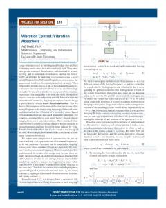
2. Theory An unbalanced load owing to rotating clothes in the drum has unpredictable position and magnitude values. To simplify the calculations, some assumptions have to be made. The first assumption is that the radius of clothes in the drum, 𝑟𝑑 , is constant. 𝑁𝑦 and 𝑁𝑧 are the components of the 𝑦- and 𝑧-axes of the unbalanced force produced by rotating clothes in the drum: 𝑁𝑧 = 𝑚𝑑 𝜔2 𝑟𝑑 cos 𝛼 + 𝑚𝑑 𝑔,
(1)
𝑁𝑦 = 𝑚𝑑 𝜔2 𝑟𝑑 sin 𝛼,
(2)
where 𝑚𝑑 is the mass of the unbalanced load; 𝑔 is the gravitational acceleration; 𝛼 is the angle between the load and the 𝑦-axis; and 𝜔 is the angular velocity of the drum around the 𝑥-axis.
Shock and Vibration
3 When 𝑥1 is less than half of 𝑑, the sum of 𝐹𝐶 and 𝐹𝐷 on the 𝑧-axis becomes greater than that of 𝐹𝐴 and 𝐹𝐵 on the 𝑧-axis:
y
x
z
Left passive spring
𝐹𝐶𝑧 + 𝐹𝐷𝑧 > 𝐹𝐴 𝑧 + 𝐹𝐵𝑧 ,
Right passive spring Unbalanced load
Tub Cabinet
FA y
Ny
D
FDy
Left semiactive suspension
Nz
Right ssemiactive suspension
FCy
C
FDz A
FBy
FA z
FCz
B
(8) 𝑑 . 2 Considering these conditions, walking instability first occurs around the front feet because they are subjected to more force than the back feet. Thus, in our study, a motion sensor is installed on the middle of the front-top panel of the washing machine. 𝑛 is the friction between the ground and the feet: 𝑥1
𝐹𝐶𝑦 + 𝐹𝐷𝑦 , 𝑥2 >
𝑑 . 2
=
(7)
(𝑚𝑑 𝜔2 𝑟𝑑 sin 𝛼) 𝑥2 𝑑
𝜔=√
(11)
,
𝑛𝑔 (𝑀𝑐 𝑥1 + 𝑚𝑑 𝑥2 ) . 𝑚𝑑 𝑟𝑑 𝑥2 (sin 𝛼 − 𝑛 cos 𝛼)
(12)
To make the equation independent of 𝛼, the derivative of (12) with respect to 𝛼 has to be equal to 0: 1 𝛼 = tan−1 (− ) . 𝑛
(13)
Then, 𝜔 becomes 𝜔=√
(4) (5)
𝑁𝑦 (𝑑 − 𝑥2 )
2 𝑀𝑐 𝑔𝑥1 (𝑚𝑑 𝜔 𝑟𝑑 cos 𝛼 + 𝑚𝑑 𝑔) 𝑥2 𝑛( + ) 𝑑 𝑑
(10)
𝑛𝑔 (𝑀𝑐 (𝑥1 /𝑥2 ) + 𝑚𝑑 ) 𝑚𝑑 𝑟𝑑 √(1 + 𝑛2 )
.
(14)
All equations shown above hold under the assumption of the rigidness of the washing machine, and they change when the washing machine contains a suspension system. Because of the structure (spring and damping elements) of the semiactive suspension system and the passive suspension system, 𝑁𝑧 and 𝑁𝑦 given by (1) and (2) change, and their new forms are, respectively, given by 𝑁𝑧 = 𝑚𝑑 𝜔2 𝑟𝑑 cos 𝛼 + 𝑚𝑑 𝑔 − 𝑘1 𝑝̂1 sin 𝛽1 − 𝑘2 𝑝̂2 sin 𝛽2 − 𝑏1
𝑑𝑝̂1 𝑑𝑝̂ sin 𝛽1 − 𝑏2 2 sin 𝛽2 𝑑𝑡 𝑑𝑡
(15)
− 𝑘3 𝑝̂3 sin 𝛽3 − 𝑘4 𝑝̂4 sin 𝛽4 , 𝑁𝑦 = 𝑚𝑑 𝜔2 𝑟𝑑 sin 𝛼 − 𝑘1 𝑝̂1 cos 𝛽1 − 𝑘2 𝑝̂2 cos 𝛽2 − 𝑏1
𝑑𝑝̂1 𝑑𝑝̂ cos 𝛽1 − 𝑏2 2 cos 𝛽2 𝑑𝑡 𝑑𝑡
− 𝑘3 𝑝̂3 cos 𝛽3 − 𝑘4 𝑝̂4 cos 𝛽4 ,
(16)
4
Shock and Vibration semiactive suspension element; 𝑝̂1 is the displacement of the left semiactive suspension element; 𝑝̂2 is the displacement of the right semiactive suspension element; 𝛽3 is the angle between the top panel and the left passive spring; 𝛽4 is the angle between the top panel and the right passive spring; 𝑝̂3 is the displacement of the left passive spring; and 𝑝̂4 is the displacement of the right passive spring. Substituting these new forms into (3) and (5) gives
where 𝑘1 is the stiffness coefficient of the left semiactive suspension element; 𝑘2 is the stiffness coefficient of the right semiactive suspension element; 𝑘3 is the stiffness coefficient of the left passive spring; 𝑘4 is the stiffness coefficient of the right passive spring; 𝑏1 is the damping coefficient of the left semiactive suspension element; 𝑏2 is the damping coefficient of the right semiactive suspension element; 𝛽1 is the angle between the ground and the left semiactive suspension element; 𝛽2 is the angle between the ground and the right 𝐹𝐴 𝑧 + 𝐹𝐵𝑧 = +
𝑀𝑐 𝑔𝑥1 𝑑
(𝑚𝑑 𝜔2 𝑟𝑑 cos 𝛼 + 𝑚𝑑 𝑔 − 𝑘1 𝑝̂1 sin 𝛽1 − 𝑘2 𝑝̂2 sin 𝛽2 − 𝑏1 (𝑑𝑝̂1 /𝑑𝑡) sin 𝛽1 − 𝑏2 (𝑑𝑝̂2 /𝑑𝑡) sin 𝛽2 − 𝑘3 𝑝̂3 sin 𝛽3 − 𝑘4 𝑝̂4 sin 𝛽4 ) 𝑥2 𝑑
,
𝐹𝐴 𝑦 + 𝐹𝐵𝑦 =
(𝑚𝑑 𝜔2 𝑟𝑑 sin 𝛼 − 𝑘1 𝑝̂1 cos 𝛽1 − 𝑘2 𝑝̂2 cos 𝛽2 − 𝑏1 (𝑑𝑝̂1 /𝑑𝑡) cos 𝛽1 − 𝑏2 (𝑑𝑝̂2 /𝑑𝑡) cos 𝛽2 − 𝑘3 𝑝̂3 cos 𝛽3 − 𝑘4 𝑝̂4 cos 𝛽4 ) 𝑥2 𝑑
[ [ 𝑛 [𝑀𝑐 𝑔𝑥1 [
,
(17)
[ 𝐴
⏞⏞⏞⏞⏞⏞⏞⏞⏞⏞⏞⏞⏞⏞⏞⏞⏞⏞⏞⏞⏞⏞⏞⏞⏞⏞⏞⏞⏞⏞⏞⏞⏞⏞⏞⏞⏞⏞⏞⏞⏞⏞⏞⏞⏞⏞⏞⏞⏞⏞⏞⏞⏞⏞⏞⏞⏞⏞⏞⏞⏞⏞⏞⏞⏞⏞⏞⏞⏞⏞⏞⏞⏞⏞⏞⏞⏞⏞⏞⏞⏞⏞⏞⏞⏞⏞⏞⏞⏞⏞⏞⏞⏞⏞⏞⏞⏞⏞⏞⏞⏞⏞⏞⏞⏞⏞⏞⏞⏞⏞⏞⏞⏞⏞⏞⏞⏞⏞⏞⏞⏞⏞⏞⏞⏞⏞⏞⏞⏞⏞⏞⏞⏞⏞⏞⏞⏞⏞⏞⏞⏞⏞⏞⏞⏞⏞⏞⏞⏞⏞⏞⏞⏞⏞⏞⏞⏞⏞⏞ ] 𝑑𝑝̂ 𝑑𝑝̂ ] + (𝑚𝑑 𝜔2 𝑟𝑑 cos 𝛼 + 𝑚𝑑 𝑔 −𝑘1 𝑝̂1 sin 𝛽1 − 𝑘2 𝑝̂2 sin 𝛽2 − 𝑏1 1 sin 𝛽1 − 𝑏2 2 sin 𝛽2 − 𝑘3 𝑝̂3 sin 𝛽3 − 𝑘4 𝑝̂4 sin 𝛽4 ) 𝑥2 ] ] 𝑑𝑡 𝑑𝑡 ] 𝐵
⏞⏞⏞⏞⏞⏞⏞⏞⏞⏞⏞⏞⏞⏞⏞⏞⏞⏞⏞⏞⏞⏞⏞⏞⏞⏞⏞⏞⏞⏞⏞⏞⏞⏞⏞⏞⏞⏞⏞⏞⏞⏞⏞⏞⏞⏞⏞⏞⏞⏞⏞⏞⏞⏞⏞⏞⏞⏞⏞⏞⏞⏞⏞⏞⏞⏞⏞⏞⏞⏞⏞⏞⏞⏞⏞⏞⏞⏞⏞⏞⏞⏞⏞⏞⏞⏞⏞⏞⏞⏞⏞⏞⏞⏞⏞⏞⏞⏞⏞⏞⏞⏞⏞⏞⏞⏞⏞⏞⏞⏞⏞⏞⏞⏞⏞⏞⏞⏞⏞⏞⏞⏞⏞⏞⏞⏞⏞⏞⏞⏞⏞⏞⏞⏞⏞⏞⏞⏞⏞⏞⏞⏞⏞⏞⏞⏞⏞⏞⏞⏞⏞⏞⏞⏞⏞⏞⏞⏞⏞⏞⏞⏞⏞ 𝑑𝑝̂ 𝑑𝑝̂ 2 = (𝑚𝑑 𝜔 𝑟𝑑 sin 𝛼 −𝑘1 𝑝̂1 cos 𝛽1 − 𝑘2 𝑝̂2 cos 𝛽2 − 𝑏1 1 cos 𝛽1 − 𝑏2 2 cos 𝛽2 − 𝑘3 𝑝̂3 cos 𝛽3 − 𝑘4 𝑝̂4 cos 𝛽4 ) 𝑥2 . 𝑑𝑡 𝑑𝑡
Thus, the walking stability threshold changes as follows: 𝜔=√
𝑛 (𝑀𝑐 𝑔𝑥1 + 𝑚𝑑 𝑔𝑥2 + 𝐴𝑥2 ) − 𝐵𝑥2 . 𝑚𝑑 𝑟𝑑 𝑥2 (sin 𝛼 − 𝑛 cos 𝛼)
(18)
As applied previously, to make the equation independent of 𝛼, the derivative of (18) with respect to 𝛼 has to be equal to 0: 𝜔=√
𝑛 (𝑀𝑐 𝑔𝑥1 + 𝑚𝑑 𝑔𝑥2 + 𝐴𝑥2 ) − 𝐵𝑥2 . 𝑚𝑑 𝑟𝑑 𝑥2 √𝑛2 + 1
(19)
Changing 𝑘1 , 𝑘2 , 𝑏1 , and 𝑏2 changes the walking stability threshold of the washing machine; this change can be achieved using a semiactive suspension system. However, owing to the structural constraints of the semiactive suspension system used in this study, the only known knowledge about the suspension elements is the maximum force value that can be produced. Therefore, it can be said that 𝑘1 𝑝̂1 + 𝑏1 (𝑑𝑝̂1 /𝑑𝑡) and 𝑘2 𝑝̂2 + 𝑏2 (𝑑𝑝̂2 /𝑑𝑡) are the only known values
in (19), and it is assumed that these values are always equal to the maximum forces produced by suspension elements. To change the maximum force values produced by the semiactive suspension elements for reducing vibrations, the angular position and angular acceleration values produced by the washing machine have to be interpreted. This can be done using the function 𝐽 that contains three-axis angular position (𝜃𝑥 , 𝜃𝑦 , and 𝜃𝑧 ) and three-axis angular acceleration (𝛼𝑥 , 𝛼𝑦 , and 𝛼𝑧 ) values, with the angular axis acceleration values being squared owing to the importance of acceleration in the vibration behavior at high frequencies: 𝐽 = 𝛼𝑥2 + 𝛼𝑦2 + 𝛼𝑧2 + 𝜃𝑥 + 𝜃𝑦 + 𝜃𝑧 .
(20)
According to the gradient of function 𝐽, the maximum force values produced by the suspension elements are chosen. When the gradient of function 𝐽 becomes higher, it indicates that the value of function 𝐽 will increase dramatically. Therefore, the vibrations will reach higher levels, to prevent which the suspension elements must apply lower force values to
Shock and Vibration
5
Table 1: Different maximum force values of suspension elements. 𝐺 0–50 50–100 100–150 150–200 200–250 250–300 300–350 350–400 400–450 450–500 500–550 550–600
Left suspension (𝑁) 120 105 95 86 76 65 55 39 28 21 18 16
Right suspension (𝑁) 112 105 90 81 72 61 51 39 28 19 13 11
the drum. Otherwise, the washing machine will show unstable vibration behavior: 𝐺=
𝐽 (𝑡) − 𝐽 (𝑡 − 𝑇𝑠 ) . 𝑇𝑠
Changing max force of semiactive suspension element according to gradient of J function Measurement of acceleration and position values in three axes
Figure 2: Flowchart of control algorithm.
𝐽 function is calculated, and the maximum forces produced by suspension elements are changed to calculate 𝜔. The second criterion is the arithmetic mean of the position and acceleration values in three axes. This criterion can also be used for investigating the changing rates of each position and acceleration parameters. Function 𝐽V is defined as follows: 𝐽V =
3. Experimental Studies Experiments were performed for the spinning cycle of a washing machine, increasing gradually from 200 rpm to 900 rpm, which produces the most challenging vibration patterns from the viewpoint of dynamic stability. The maximum weight capacity of the washing machine is 7 kg. The equation shown below is used as the first evaluation criterion (Papadopoulas and Papadimitriou’s walking stability threshold adapted to a horizontal axis washing machine working with semiactive suspension system) for the success of the controlled semiactive suspension system. 𝑀 is the magnitude of 𝜔 at each sampling time and 𝑁 is the sum of samples: ∑𝑁 𝑖=0 𝑀𝑖 . 𝑁
Calculation of gradient of J function for each sample
(21)
The intervals of function 𝐺 for different maximum force values of suspension elements are shown in Table 1. Each interval corresponds to a different vibration level of the washing machine, and the maximum forces applied by the semiactive suspension elements change to reduce the vibrations so as to deal with the dynamic stability problem that may occur during the spinning cycle. While the gradient of 𝐽 increases, the maximum forces produced by the suspension elements decrease and vice versa. This process directly changes the effects of the suspension elements in the equation for the walking stability condition (19). Figure 2 shows the flowchart of the control algorithm used, for a better understanding.
𝐽𝜔 =
Creating J function
(22)
The higher the value of function 𝐽𝜔 , the more stable the washing machine. 𝜔 values have to be calculated for each sampling time to obtain 𝐽𝜔 values. As mentioned before, for each sampling time, vibration data are recorded, gradient of
∑𝑁 𝑖=0 𝐾𝑖 , 𝑁
(23)
where 𝐾 is the magnitude of each signal (position or acceleration) at each sampling time and 𝑁 is the sum of samples. The lower the value of function 𝐽V is, the less oscillation it shows from its initial value 0, indicating the success of the controller. The process of changing the maximum forces of suspension elements can only be achieved at the same time owing to the structure of the motor drive module. A positive edge PWM signal is sent from the DAQ card to the motor drive module through a circuit including a 3 k resistor and an NPN transistor, as shown in Figure 3. The connection between the resistor and the transistor is serial in nature. A single PWM signal makes the suspension elements take only one step on the gradient line, and the number of PWM signals that have to be produced by the DAQ card is selected according to the gradient of function 𝐽. For instance, if the gradient of function 𝐽 is 3 at time 𝑡 and 6 at time 𝑡 + 𝑇𝑠 , three PWM signals have to be produced to change the maximum forces of the suspension elements. 𝑇𝑠 is selected as 300 ms for data acquisition and as 600 ms for control signal that drives step motors. The MPU 6050 motion sensor is used in this study. It includes a 3-axis accelerometer and 3-axis gyroscope, and it has 16-bit analog-digital converters for digitizing the accelerometer and gyroscope outputs. The userprogrammable gyroscope scale is adjusted to ±2000∘ /s and the user-programmable accelerometer scale to ±16 g. Even though the DAQ card provides 5 V, the sensor has a voltage regulator for its working voltage of 3.3 V. Communication with the data acquisition card is performed using the I2 C protocol at 400 Hz from the SCL and SDA channels. The communication software is programmed in MATLAB using the C programming language. As mentioned in (8), walking instability first occurs around the front feet because they are subject to more force than the back feet. Thus, the sensor is
Shock and Vibration
Right suspension element
M
6
NPN Motor drive module
Washing machine
B Step motor
NPN 3k
M
Left suspension element
3k
A
Data cable
Bracelet Suspension element
Figure 5: Semiactive suspension element. Sensor
DAQ card
Figure 3: Motor drive module, sensor, and DAQ card connection.
DAQ card
Sensor
Figure 6: Washing machine in anechoic chamber.
Figure 4: Sensor and DAQ card.
installed on the middle of the front-top panel of the washing machine, as shown in Figure 4. The Arduino Mega 2560 DAQ card is used in this study. It includes an ATmega microcontroller, and communication between the PC and the DAQ card is performed using the serial communication protocol. A positive edge PWM signal is sent from the digital pin of the DAQ card after receiving sensor data. The communication software is programmed in MATLAB using the C programming language. The semiactive suspension system used in this study is shown in Figure 5. Inside the suspension elements, there is a cylindrical mass made of polyurethane. The data cable carries a signal from the motor drive module that drives the step motor. Depending on the type of signal, the bracelet starts to narrow or expand, causing a change in the elastic properties of the suspension element. The experiments are performed in a semianechoic room, as shown in Figure 6. The sound power levels for uncontrolled and controlled suspension systems are measured according to ISO 3745. The physical parameters of the washing machine are listed in Table 2. The trajectory of the passive spring elements is assumed to be 0.1 sin(5𝑡) and 𝛽1 , 𝛽2 , 𝛽3 , and 𝛽4 are assumed to be constant and equal to 55∘ . The friction coefficient between
the feet and the ground is assumed to be constant and equal to 5.
4. Results and Discussion To show the success of the control method in damping vibrations, the measured position and acceleration values when the semiactive suspension system is uncontrolled (maximum force of left and right suspensions is 120 and 112, resp.) and controlled are shown in Figures 7–18. As can be seen in Figure 7, for controlled system, variation between minimum and maximum values of 𝜃𝑥 is considerably low. Minimum value of 𝜃𝑥 is −6∘ and maximum value of 𝜃𝑥 is +6∘ . On the other hand, for uncontrolled system shown in Figure 8, the value of 𝜃𝑥 oscillates between −60∘ and +60∘ , which means that 90% reduction of minimum and maximum values of vibration for 𝑥-axis is confirmed. Moreover, in Figure 7, it can be seen that the value of 𝜃𝑥 settles around −1∘ ; the reason of this situation is the noise that corrupts sensor data. In Figure 9, the value of 𝜃𝑦 for controlled system settles around 0∘ with a low value of steady-state error, which is described with 𝐽V in Table 3; variation between minimum and maximum values of 𝜃𝑦 is considerably low. Minimum value of 𝜃𝑦 is −6∘ and maximum value of 𝜃𝑦 is +6∘ . For uncontrolled system as shown in Figure 10, the value of 𝜃𝑦 oscillates between −60∘ and +40∘ , which means that minimum value
Shock and Vibration
7 Table 2: Physical parameters.
𝐷 [m]
𝑥2 [m]
𝑀𝑐 [kg]
𝑁
𝑘3 and 𝑘4 [N/m]
Trajectory [m]
𝑟𝑑 [m]
𝑚𝑑 [kg]
𝛽1 , 𝛽2 , 𝛽3 , and 𝛽4 [∘ ]
0.2
0.34
67
5
250
0.1 Sin(5𝑡)
0.2
10
55
60
60
40
40
20
20 𝜃y ( ∘ )
𝜃x ( ∘ )
0.54
𝑥1 [m]
0
0
−20
−20
−40
−40
−60
0
0.5
1 1.5 Sampling number
2
2.5 ×10⁴
−60
Figure 7: 𝜃𝑥 for controlled system.
1 1.5 Sampling number
2
2.5 ×10⁴
Table 3: 𝐽V values of position and acceleration data for controlled and uncontrolled suspension system. 𝐽V values 𝜃𝑥 [∘ ] 𝜃𝑦 [∘ ] 𝜃𝑧 [∘ ] 𝛼𝑥 [∘ /s2 ] 𝛼𝑦 [∘ /s2 ] 𝛼𝑧 [∘ /s2 ] Controlled 0.31 0.23 1.29 0.29 0.23 0.23 Uncontrolled 21.13 19.36 2.11 0.53 0.95 0.57
40 20
𝜃x ( ∘ )
0.5
Figure 9: 𝜃𝑦 for controlled system.
60
Table 4: Improvement percentage of 𝐽V values for position and acceleration data compared with their uncontrolled values.
0 −20
𝜃𝑥 98.53%
−40 −60
0
0
0.5
1 1.5 Sampling number
2
2.5 ×10⁴
Figure 8: 𝜃𝑥 for uncontrolled system.
of vibration in 𝑦-axis is reduced by 90%, whereas maximum value of vibration in 𝑦-axis is reduced by 85%. In Figure 11, the value of 𝜃𝑧 for controlled system settles around 0∘ ; peak values of 𝜃𝑧 are high with respect to steadystate error of 𝜃𝑧 , whereas the value of 𝜃𝑧 settles around +2∘ for uncontrolled system as shown in Figure 12. As can be seen from Figures 7–12, even though there are some peak values, vibrations in 𝑥-, 𝑦-, and 𝑧-axes are considerably reduced for controlled system, especially for 𝜃𝑥 and 𝜃𝑦 parameters. Comparison for angular acceleration parameters is shown in Figures 13–18.
𝜃𝑦 98.81%
𝜃𝑧 38.86%
𝛼𝑥 45.28%
𝛼𝑦 75.78%
𝛼𝑧 59.64%
In Figure 13, the value of 𝛼𝑥 for controlled system settles around −0.4∘ ; peak values of 𝛼𝑥 are high with respect to steady-state error of 𝛼𝑥 and increase through the end of washing operation. For uncontrolled system shown in Figure 14, it can be seen that the value of 𝛼𝑥 oscillates between −1∘ and +0.7∘ . In Figure 15, the value of 𝛼𝑦 for controlled system settles around 0∘ ; peak values of 𝛼𝑦 are the highest ones among other angular acceleration parameters shown in Figures 13 and 17. However, this situation does not corrupt improvement percentage of 𝐽V as can be seen in Table 4. For uncontrolled system shown in Figure 16, it can be seen that the value of 𝛼𝑥 oscillates between −1∘ and +0.7∘ and there are minimum and maximum peak values around −4∘ and +4∘ , respectively. In Figure 17, the value of 𝛼𝑧 for controlled system settles around 0∘ and varies between −2∘ and +2.5∘ . For uncontrolled system shown in Figure 18, 𝛼𝑧 settles around 0∘ with high frequency change.
8
Shock and Vibration 60
2
40
1 0 𝛼x ( /s2 )
0 −20
−2 −3
−40 −60
−1
∘
𝜃y ( ∘ )
20
−4 0
0.5
1
1.5
2
×10
Sampling number
−5
2.5 4
0
Figure 10: 𝜃𝑦 for uncontrolled system.
2
4
1
2
2.5 ×10⁴
0 𝛼x ( /s2 )
2 0
−1
∘
𝜃z ( ∘ )
1 1.5 Sampling number
Figure 13: 𝛼𝑥 for controlled system.
6
−2
−2 −3
−4 −6
0.5
−4
0
0.5
1
1.5
2
−5
2.5
0
0.5
×104
Sampling number
1
1.5
2
2.5 ×10⁴
Sampling number
Figure 14: 𝛼𝑥 for uncontrolled system.
Figure 11: 𝜃𝑧 for controlled system.
6
5 4
4
3 2 𝛼y ( /s2 )
0
∘
𝜃z ( ∘ )
2
−2
0 −1 −2 −3
−4 −6
1
−4 0
0.5
1
1.5
Sampling number
Figure 12: 𝜃𝑧 for uncontrolled system.
2
2.5 ×10⁴
−5
0
0.5
1
1.5
Sampling number
Figure 15: 𝛼𝑦 for controlled system.
2
2.5 ×10⁴
9
5
1400
4
1300
3
1200
2
1100
1
1000
𝜔 (rev/min)
∘
𝛼y ( /s2 )
Shock and Vibration
0 −1
900 800
−2
700
−3
600
−4
500
−5
400 0
0.5
1 1.5 Sampling number
2
2.5 ×10⁴
0
0.5
1 1.5 Sampling number
2
2.5 ×10⁴
Figure 19: 𝜔 for controlled suspension system.
Figure 16: 𝛼𝑦 for uncontrolled system. 75
Sound power level (dBA)
3 2
∘
𝛼z ( /s2 )
1 0
70
65
60
55
−1 50 −2 −3
0
0.5
1
1.5
2
2.5 ×10⁴
Sampling number
Figure 17: 𝛼𝑧 for controlled system.
3 2
∘
𝛼z ( /s2 )
1 0 −1 −2 −3
0
0.5
1 1.5 Sampling number
2
Figure 18: 𝛼𝑧 for uncontrolled system.
2.5 ×10⁴
0
100
200
300
400 500 Time (s)
600
700
800
Controlled suspension system Uncontrolled suspension system
Figure 20: Measured sound power levels for controlled and uncontrolled suspension systems.
As can be seen from Figures 13, 15, and 17, angular acceleration parameters for controlled system have peaks, just as angular position parameters shown in Figures 7, 9, and 11; however, in this case, the peak values reach beyond the boundaries of uncontrolled system’s angular acceleration outputs. The main reason of the existence of these peak values is that, due to hardware constraints, the sampling time 𝑇𝑠 is adjusted to 300 ms for data acquisition while it is adjusted to 600 ms for control signal that drives step motors. When the gradient of function 𝐽 drastically changes (and the system becomes prone to be unstable), the control signal cannot quickly affect the system because of time delay between data acquisition and control signal. The 𝐽V values of each position and acceleration data for a controlled and an uncontrolled semiactive suspension system are listed in Table 3. Table 4 suggests that the controller mostly succeeds in terms of the position 𝜃𝑦 and acceleration 𝛼𝑦 .
10 The change in 𝜔 over time is shown in Figure 19; 𝐽𝜔 is calculated as 1080.2 rpm. Sound power levels of the washing machine for controlled and uncontrolled cases have also been measured according to ISO 3745 in a semianechoic room as shown in Figure 6 and the measurement results are presented in Figure 20. Figure 20 shows that at the low spin speeds the sound power level is more stable when the semiactive suspension system is controlled; in comparison, the uncontrolled system shows more oscillatory behavior for the first spinning cycles. At the highest final spin speed, 900 rpm, Figure 20 shows that there is no major difference between the measured sound power levels. In Figure 20, it can be seen that the value of sound power changes between 50 dBA and 63 dBA when the system is uncontrolled and the value of sound power changes between 54 dBA and 62 dBA when the system is controlled for the first spinning cycles.
Shock and Vibration
[4]
[5]
[6]
[7]
[8]
5. Conclusions This study proves that low-cost equipment including an MPU 6050 sensor, an Arduino Mega 2560 used as data acquisition card, and a semiactive suspension system working based on maximum force adjustment can be used to solve the walking instability problem of washing machines. When the system is controlled, angular position values in 𝑥-, 𝑦-, and 𝑧-axes settle around 0∘ with low steady-state errors, which means that they are considerably reduced. Even though angular acceleration values have peaks during the operation, they have not any major effects on walking and dynamic stability. Finally, the measured sound power levels prove that a washing machine with a controlled semiactive suspension system shows more stable sound performance than an uncontrolled one for the spinning cycle. Furthermore, even though there is an enormous difference between the controlled and the uncontrolled semiactive suspension systems from the viewpoint of vibration damping, the final sound power levels of the washing machine for both conditions are almost the same (72 dBA and 73 dBA), suggesting that there is no linear relation between vibrations causing walking instability and sound power levels produced by the washing machine in this case.
Conflict of Interests The authors declare that there is no conflict of interests regarding the publication of this paper.
References [1] D. C. Conrad and W. Soedel, “On the problem of oscillatory walk of automatic washing machines,” Journal of Sound and Vibration, vol. 188, no. 3, pp. 301–314, 1995. [2] D. C. Conrad, The fundamentals of automatic washing machine design based upon dynamic constraints [Ph.D. thesis], Purdue University, Ann Arbor, Mich, USA, 1994. [3] T. Nyg˚ards and V. Berbyuk, “Optimization of washing machine kinematics, dynamics, and stability during spinning using a
[9]
[10]
[11]
multistep approach,” Optimization and Engineering, vol. 15, no. 2, pp. 401–442, 2014. A. Ashfak, K. K. A. Rasheed, and J. A. Jaleel, “Modeling, simulation and experimental validation of Magneto-Rheological damper,” in Proceedings of the International Conference on Advanced Nanomaterials and Emerging Engineering Technologies (ICANMEET ’13), pp. 267–274, July 2013. C. Spelta, F. Previdi, S. M. Savaresi, G. Fraternale, and N. Gaudiano, “Control of magnetorheological dampers for vibration reduction in a washing machine,” Mechatronics, vol. 19, no. 3, pp. 410–421, 2009. O. S. T¨urkay, B. Kiray, A. K. Tugcu, and ˙I. T. S¨umer, “Formulation and implementation of parametric optimisation of a washing machine suspension system,” Mechanical Systems and Signal Processing, vol. 9, no. 4, pp. 359–377, 1995. O. S. T¨urkay, I. T. S¨umer, A. K. Tu˘gcu, and B. Kiray, “Modeling and experimental assessment of suspension dynamics of a horizontal-axis washing machine,” Journal of Vibration and Acoustics, vol. 120, no. 2, pp. 534–543, 1998. P. Boyraz and M. G¨und¨uz, “Dynamic modeling of a horizontal washing machine and optimization of vibration characteristics using Genetic Algorithms,” Mechatronics, vol. 23, no. 6, pp. 581– 593, 2013. ¨ urk and H. Erol, “On the dynamics of a washing M. E. Ozt¨ machine with flexible components,” Noise Control Engineering Journal, vol. 58, no. 6, pp. 572–590, 2010. E. Papadopoulos and I. Papadimitriou, “Modeling, design and control of a portable washing machine during the spinning cycle,” in Proceedings of the IEEE/ASME International Conference on Advanced Intelligent Mechatronics, pp. 899–904, July 2001. M. Kalkat, “Experimentally vibration and noise analysis of two types of washing machines with a proposed neural network predictor,” Measurement, vol. 47, no. 1, pp. 184–192, 2014.
International Journal of
Rotating Machinery
The Scientific World Journal Hindawi Publishing Corporation http://www.hindawi.com
Volume 2014
Engineering Journal of
Hindawi Publishing Corporation http://www.hindawi.com
Volume 2014
Hindawi Publishing Corporation http://www.hindawi.com
Volume 2014
Advances in
Mechanical Engineering
Journal of
Sensors Hindawi Publishing Corporation http://www.hindawi.com
Volume 2014
International Journal of
Distributed Sensor Networks Hindawi Publishing Corporation http://www.hindawi.com
Hindawi Publishing Corporation http://www.hindawi.com
Volume 2014
Advances in
Civil Engineering Hindawi Publishing Corporation http://www.hindawi.com
Volume 2014
Volume 2014
Submit your manuscripts at http://www.hindawi.com
Advances in OptoElectronics
Journal of
Robotics Hindawi Publishing Corporation http://www.hindawi.com
Hindawi Publishing Corporation http://www.hindawi.com
Volume 2014
Volume 2014
VLSI Design
Modelling & Simulation in Engineering
International Journal of
Navigation and Observation
International Journal of
Chemical Engineering Hindawi Publishing Corporation http://www.hindawi.com
Volume 2014
Hindawi Publishing Corporation http://www.hindawi.com
Hindawi Publishing Corporation http://www.hindawi.com
Volume 2014
Hindawi Publishing Corporation http://www.hindawi.com
Advances in
Acoustics and Vibration Volume 2014
Hindawi Publishing Corporation http://www.hindawi.com
Volume 2014
Volume 2014
Journal of
Control Science and Engineering
Active and Passive Electronic Components Hindawi Publishing Corporation http://www.hindawi.com
Volume 2014
International Journal of
Journal of
Antennas and Propagation Hindawi Publishing Corporation http://www.hindawi.com
Shock and Vibration Volume 2014
Hindawi Publishing Corporation http://www.hindawi.com
Volume 2014
Hindawi Publishing Corporation http://www.hindawi.com
Volume 2014
Electrical and Computer Engineering Hindawi Publishing Corporation http://www.hindawi.com
Volume 2014