Hindawi Publishing Corporation Mathematical Problems in Engineering Volume 2015, Article ID 608737, 17 pages http://dx.doi.org/10.1155/2015/608737
Research Article Torsional Vibration Semiactive Control of Drivetrain Based on Magnetorheological Fluid Dual Mass Flywheel Qing-hua Zu, Zhi-yong Chen, Wen-ku Shi, Yang Mao, and Zhi-yuan Chen State Key Laboratory of Automotive Simulation and Control, Jilin University, Changchun 130022, China Correspondence should be addressed to Zhi-yong Chen; chen
[email protected] Received 14 September 2015; Revised 25 November 2015; Accepted 26 November 2015 Academic Editor: Erik Cuevas Copyright © 2015 Qing-hua Zu et al. This is an open access article distributed under the Creative Commons Attribution License, which permits unrestricted use, distribution, and reproduction in any medium, provided the original work is properly cited. The damping characteristics of the traditional dual mass flywheel (DMF) cannot be changed and can only meet one of the damping requirements. Given that the traditional DMF cannot avoid the resonance interval in start/stop conditions, it tends to generate highresonance amplitude, which reduces the lifetime of a vehicle’s parts and leads to vehicle vibration and noise. The problems associated with the traditional DMF can be solved through the magnetorheological fluid dual mass flywheel (MRF-DMF), which was designed in this study with adjustable damping performance under different conditions. The MRF-DMF is designed based on the rheological behavior of the magnetorheological fluid (MRF), which can be changed by magnetic field strength. The damping torque of the MRF-DMF, which is generated by the MRF effect, is derived in detail. Thus, the cosimulation between the drivetrain model built in AMESim and the control system model developed in Simulink is conducted. The controller of MRF-DMF is developed, after which the torsional vibration control test of drivetrain is carried out. The cosimulation and test results indicate that MRF-DMF with the controller effectively isolates torque fluctuation of the engine in the driving condition and exhibits high performance in suppressing the resonance amplitude in the start/stop conditions.
1. Introduction With economic development and elevated living standards, vehicles have gradually become a necessity of daily life and work. NVH (i.e., Noise, Vibration, and Harshness) performance is becoming an important issue for passengers. Many factors affect the NVH performance of a vehicle, and among these torsional vibration of the drivetrain is one of the most crucial [1]. An investigation of the torsional vibration mode of the vehicular clutch system indicates that because of the irregular torque of an engine, the drivetrain may generate serious problems in the form of torsional vibration and noise without effective control methods [2]. A previous study discussed the principal feature of torsional vibration in automobile transmission system and suggested ways to decrease noise; the same article argued that reducing the torque fluctuation amplitude of the engine and the torque fluctuation transmissibility are effective methods in alleviating the influence of engine torque fluctuation on the drivetrain [3]. However, reducing the torque fluctuation amplitude of the engine is
difficult because torque fluctuation is an inherent characteristic of a reciprocating piston engine. Thus, reducing torque fluctuation transmissibility is determined to be the more effective and feasible method between the two. Clutch torsional damper (CTD) is a widely used torsional damping device [4, 5]. A simulation method has been introduced [6] so that the effect on judder phenomena can be evaluated. A previous work [7] presented the advantages of the dual mass flywheel (DMF), compared the CTD and DMF, and determined the limitations of the CTD. In that study, the damping characteristics of CTD are found to be insufficient in isolating torque fluctuation because of the high torsional stiffness and limited space. The DMF, which uses low torsional stiffness, breaks through the limit of space. The development, advantages, and new generations of the DMF are presented in previous work in literature [8]. The DMF has also been demonstrated to damp the torque fluctuation in an engine during the idle and driving conditions and reduce torsional vibration resonance frequency below idle speed. Owing to its perfect isolation characteristics, the DMF has been widely used in many vehicles and has various patterns,
2 such as helical spring DMF, rubber spring DMF, hydraulic damping DMF, and air damping DMF. The helical spring DMF, which contains radial helical spring and circumference helical spring, has been the most widely used DMF pattern in recent years. Circumference helical spring can be categorized into two types, namely, long arc spring DMF and short spring DMF [9–12]. Great progress has been made in DMF in recent years. The study of DMF with centrifugal pendulum vibration absorbers system shows that, instead of just damping vibrations at a specific frequency, it could damp vibrations over a range of frequencies [13]. A new structure of DMF with continuously variable stiffness is proposed to lower the idle speed of the engine, realize high counter torque at a large torsional angle, and avoid the impact due to the abrupt changes of stiffness [14]. By establishing nonlinear dynamic model of the proposed damper, its dynamic characteristics are analyzed, and the result shows that torsional vibration control effect of the proposed damper is better than the traditional dual mass flywheel type torsional vibration damper [15]. The DMF can damp the torque fluctuation in an engine during the idle and driving conditions and reduce torsional vibration resonance frequency below the idle speed [8, 9, 13– 15]. However, when the DMF is utilized, high-resonance amplitude is generated when the rotating speed of the drivetrain passes the resonance interval, particularly during the start and stop conditions, which leads to vehicle vibration and noise as well as the reduced life spans of the vehicle’s parts. Although the resonance amplitude can be reduced by increasing damping, torsional vibration damping performance would decrease in the idle and driving conditions. In conclusion, the traditional DMF without adjustable damping characteristic could not satisfy the damping characteristic requirements of a drivetrain under different conditions. Hence, the traditional DMF could not avoid resonance interval in the start/stop conditions and generates highresonance amplitude, which again, leads to vehicle vibration and noise and reduced life span of its parts. To satisfy the different damping characteristic requirements of a drivetrain under different conditions, the magnetorheological fluid dual mass flywheel (MRF-DMF) [16, 17] with adjustable damping characteristics is designed and manufactured in this paper. The design of this new type of DMF is based on the behavior of the magnetorheological fluid (MRF), which can be changed by the magnetic field intensity [18–21]. The damping characteristic of the device can be changed by magnetic field intensity, which is adjusted by the current. Strong damping characteristic is produced to reduce the resonance amplitude in the start, stop, and other resonance conditions, whereas weak damping characteristic is generated to isolate engine torque fluctuation under idle and driving conditions. To achieve better vibration isolation of a drivetrain in each condition, the damping characteristic of the MRFDMF must be adjustable under different conditions, which is referred to as semiactive control. The following semiactive control strategies offer a wide range of applications at present, including ON/OFF control, PID control, fuzzy control, and neural network control [22–24]. ON/OFF control only has two conditions of on and off, and this makes it ineffective
Mathematical Problems in Engineering various conditions. PID control can be applied in simple processes but not in complex processes. Neural network control is comparatively complex and requires extensive training to ensure effectiveness. After a comprehensive consideration, the current paper employs fuzzy control strategy to achieve real-time control of the damping characteristic of the model. This is because fuzzy control can be easily achieved and applies well to a variety of complex conditions. Significant work has been done in the past few years. The fluid-structure interaction finite element model of the MRF-DMF is established to analyze the parameters [21]. To control the torsional damper of the MRF-DMF, MRFDMF is designed and proposed, and its AMESim model is constructed and verified by a bench test [17, 18]. The current paper introduces the operating and control principles of the MRF-DMF and deduces its damping torque, which is generated by the MRF effect. The study also examines the damping effect of MRF-DMF under fuzzy control in different conditions and carries out a test comparison of the damping effect of the MRF-DMF with that of traditional DMF. The results of the simulation and the experiment demonstrate that the MRF-DMF with a controller that uses fuzzy control effectively isolates the torque fluctuation of the engine under the driving condition and suppresses the resonance amplitude under the start and stop conditions. The test comparison results also indicate that the MRF-DMF performs significantly better than the traditional DMF in suppressing the resonance amplitude under the start and stop conditions. The results further indicate that the MRF-DMF that has been designed and manufactured in this paper addresses the problem associated with the traditional DMF, in which the different damping characteristic requirements of the drivetrain under different conditions could not be satisfied. Thus, the MRF-DMF can be widely used on vehicles in the future to improve NVH performance.
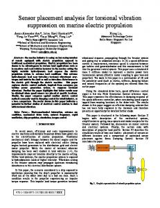
2. System Architecture Installing a controllable damping device is necessary to satisfy the specific damping requirements under different conditions. In normal driving conditions, a weak damping characteristic is needed to isolate the torsional vibration transferred from the engine to the transmission. By contrast, a strong damping characteristic is required to reduce the resonance amplitude of the powertrain under different resonance conditions, such as engine start and stop. To increase the effectiveness of the DMF in controlling the torsional vibration of drivetrain, its structure can be improved by paralleling a timely controllable damping device with the arc spring of the DMF, as shown in Figure 1. Thus, the required damping characteristic can be satisfied under different conditions, and the torsional vibration characteristic of a drivetrain can be timely controlled. To achieve the timely and fully controllable damping characteristic of the DMF under different conditions, this paper considered the rheological behavior of the MRF, which can be adjusted by changing the magnetic field intensity [18– 21] and designed the MRF-DMF. Exciting coil is mounted out
Mathematical Problems in Engineering
3 10
First mass
11
Arc spring Second mass
12 13 14 15 16 17 18
9 Transmission Engine Clutch Controllable damping device Controller
Figure 1: Architecture of the drivetrain.
of the MRF area. The damping characteristic of the MRFDMF could be timely controlled by changing the rheological behavior of the MRF, which could be controlled by the magnetic field intensity generated by different coil currents. The structure of the MRF-DMF is shown in Figure 2. The area between the inner rotor and outer rotor is filled up with magnetorheological fluid. The magnetic field strength of this area is controlled by the current of the exciting coils. An arc spring is mounted between the first flywheel and the second flywheel. The outer rotor and the first flywheel comprise the first mass, which connects the crankshaft of engine. The inner rotor and the second flywheel make up the second mass, which connects transmission through the clutch. The exciting coil will not be powered on when the drivetrain needs a weak damping, such as in the idle and driving conditions. In this case, the MRF performance characteristics of the Newtonian fluid and the damping between the inner and outer rotors become weak. The exciting coil will be powered on when the drivetrain requires a strong damping, such as in the engine start and stop conditions. In this case, the MRF performance characteristic of the Bingham fluid and the damping between the inner and outer rotors become strong.
3. Analysis of Damping Characteristics As a key characteristic of the MRF-DMF, which is crucial in solving the torsional vibration problem, the damping characteristic mainly depends on the shear force produced by shearing the MRF, while the inner and outer rotors generate the relative rotation. The shearing area can be divided into two parts, namely, top gap and side gap. The following assumptions are made in establishing the mathematical model: (1) The MRF is an incompressible fluid. (2) The MRF exhibits a steady flow. (3) The MRF only shows circumferential shear flow (without axial and radial flow). (4) The effect of gravity of the MRF itself is disregarded. (5) Magnetic field intensity is uniformly distributed in the gap. (6) The pressure of the MRF is consistent in the radial direction.
8 7 6 5 4 3
19 20 21
2
22 17 23
1
Figure 2: Structure of the MRF-DMF. 1: inner rotor connecting shaft, 2: crankshaft side connecting hole, 3: bearing, 4: rivet, 5: first mass, 6: force transmission board, 7: arc spring, 8: guide chute, 9: test point of rotating speed sensor, 10: starting ring gear, 11: ring gear, 12: friction surface of clutch, 13: magnetic yoke, 14: exciting coil, 15/1622: magnetic isolation material, 17: outer rotor, 18: liquid injection hole, 19: inner rotor, 20: magnetorheological fluid, 21: seal ring, and 23: support shaft. l4
Outer rotor
𝜔1 𝜔2 ry
Inner rotor
r6
MRF
𝜔y
r5
Figure 3: Top gap.
3.1. Damping Characteristics in the Top Gap. The shape of the top gap is illustrated in Figure 3. When the inner and outer rotors relatively rotate, the damping torque in this area can be derived as the following derivations. The MRF under zero magnetic field has the characteristics of the Newtonian and Bingham fluids under a magnetic field. The equation is given as follows: 𝜏 = 𝜂𝛾,̇
(1)
𝜏 = 𝜏𝐵 sgn (𝛾)̇ + 𝜂𝛾;̇ 𝛾̇ = 0;
(|𝜏| ≥ 𝜏𝐵 )
(|𝜏| < 𝜏𝐵 ) ,
(2)
where 𝜏 represents the shear stress of the MRF in Pa, 𝜂 denotes the dynamic viscosity of the MRF in Pa⋅s, 𝛾̇ represents the shear strain rate of the MRF in 1/s, and 𝜏𝐵 denotes the shear yield stress of the MRF in Pa. Based on the Navier-Stokes equation of hydromechanics, the circumferential momentum equation could be obtained by 𝜌
𝜕2 𝑢 1 𝜕𝑢 𝑢 𝜕𝑢 = 𝜂( 2 + − ), 𝜕𝑡 𝜕𝑟 𝑟 𝜕𝑟 𝑟2
(3)
4
Mathematical Problems in Engineering
where 𝜌 represents the density of the magnetorheological fluid, 𝜂 denotes the viscosity of the magnetorheological fluid, 𝑢 indicates the circumferential velocity of the magnetorheological fluid, and 𝑟 represents the radial velocity of the magnetorheological fluid. The relationship of shear stress and shear strain rate is described by 𝜏 = 𝜂(
𝜕𝑢 𝑢 − ). 𝜕𝑟 𝑟
(4)
Taking partial derivative of (4) with respect to 𝑟 is given by 𝜕𝜏 𝜕2 𝑢 1 𝜕𝑢 𝑢 = 𝜂( 2 − + ). 𝜕𝑟 𝜕𝑟 𝑟 𝜕𝑟 𝑟2
(5)
Equation (3) minus (5) is given by 𝜕𝑢 𝜕𝜏 2 𝜕𝑢 𝑢 2𝜏 𝜌 − = [𝜂 ( − )] = . 𝜕𝑡 𝜕𝑟 𝑟 𝜕𝑟 𝑟 𝑟
𝑐1 = (6)
Considering the assumptions of (2) and (3) stated above, the MRF has a constant speed at a certain radius, so 𝜕𝑢/𝜕𝑡 = 0. Equation (7) is thus obtained: 𝜕𝜏 2𝜏 + = 0. 𝜕𝑟 𝑟 𝑐1 , 𝑟2
(8)
where 𝑐1 represents the integration constant in the equation. The shear strain rate is given by 𝛾̇ = 𝑟
𝑑 𝑢 (𝑟) ( ), 𝑑𝑟 𝑟
(9)
where 𝑢(𝑟) denotes the velocity of the magnetorheological fluid. By considering (8), (9), and (2) (when |𝜏| ≥ 𝜏𝐵 ) as simultaneous equations, (10) is thus obtained: 𝑑 𝑢 (𝑟) 1 𝑐1 𝜏𝐵top ̇ . ( − ( )= sgn (𝛾)) 𝑑𝑟 𝑟 𝜂0 𝑟3 𝑟
(10)
The inner and outer rotors are assumed to have the same rotation directions but with different speed levels. Thus, sgn(𝛾)̇ = 1, and (10) is integrated to obtain 𝑐 𝑟 [− 12 − 𝜏𝐵top ln 𝑟] + 𝑐2 𝑟, 𝑢 (𝑟) = 𝜂0 2𝑟
2𝜂0 𝑟52 𝑟𝑦2 𝜏𝐵top 𝑟𝑦 ln + 𝜔1 − 𝜔2 ] , [ 𝜂0 𝑟5 𝑟𝑦2 − 𝑟52
𝑐2 = 𝜔1 +
(11)
where 𝑐2 represents the integration constant in the equation, 𝜏𝐵top denotes the shear stress of the MRF in the top gap, and 𝜂0 indicates the dynamic viscosity of the MRF under the zero magnetic field. Consider the torque 𝑇 is transmitted between the inner shaft and the outer shaft. Depending on the magnitude of 𝑇, three scenarios exist, as described below.
(12)
𝜏𝐵top 𝑟𝑦 𝑟52 𝜏 [ ln + 𝜔1 − 𝜔2 ] + 𝐵 ln 𝑟𝑦 . (13) 𝑟5 𝜂0 𝑟𝑦2 − 𝑟52 𝜂0
In the place of radius 𝑟, the MRF generates torque 𝑇𝑟 as given by
(7)
By solving (7), (8) is obtained, which is given by 𝜏=
(a) If 𝑇 ≤ 𝑇1 (where 𝑇1 = 2𝜋𝑟52 𝑙4 𝜏𝐵 and 𝜏𝐵 is the fluid shear yield stress), the whole fluid in the gap acts as a solid. The first and second masses move together, and the spring between the two masses does not deflect. Thus, no vibration occurs. (b) If 𝑇1 < 𝑇 ≤ 𝑇2 (where 𝑇1 = 2𝜋𝑟62 𝑙4 𝜏𝐵 ), the inner part of the fluid in the gap starts to flow, while the upper part of the fluid in the gap is still solid. The boundary of the flowing part and the solid part is the area where shear yield stress 𝜏𝐵 occurs, whose radius can be calculated as 𝑟𝑦 = √𝑇/2𝜋𝑙4 𝜏𝐵 . The velocity at 𝑟𝑦 is 𝑢(𝑟𝑦 ) = 𝑟𝜔𝑦 = 𝑟𝜔1 , and the velocity at 𝑟5 is 𝑢(𝑟5 ) = 𝑟𝜔2 . The rotative speeds of the inner and outer roters are 𝜔2 and 𝜔1 , respectively, and the rotative speed of the liquid-solid boundary is 𝜔𝑦 . Integrating the boundary conditions of 𝑢(𝑟) into (11), 𝑐1 and 𝑐2 are obtained, respectively, as
𝑇𝑟 = 2𝜋𝑟2 𝑙4 𝜏.
(14)
By including (8) and (12) into (14) and assigning Δ𝜔 = 𝜔2 − 𝜔1 , the damping torque generated by the MRF in the top gap is given by 𝑇top = 4𝜋𝜏𝐵top 𝑙4
𝑟52 𝑟𝑦2 𝑟52 − 𝑟𝑦2
ln
𝑟52 𝑟𝑦2 𝑟5 + 4𝜋𝜂0 𝑙4 2 Δ𝜔. 𝑟𝑦 𝑟5 − 𝑟𝑦2
(15)
(c) If 𝑇 > 𝑇2 , the fluid in the gap flows. In this case, the velocity at 𝑟6 is 𝑢(𝑟6 ) = 𝑟𝜔1 and the velocity at 𝑟5 is 𝑢(𝑟5 ) = 𝑟𝜔2 . By integrating the boundary conditions of 𝑢(𝑟), 𝑢(𝑟6 ) = 𝑟𝜔1 and 𝑢(𝑟5 ) = 𝑟𝜔2 , into (11), 𝑐1 and 𝑐2 are, respetively, obtained as 𝑐1 =
2𝜂0 𝑟52 𝑟62 𝜏𝐵top 𝑟6 [ ln + 𝜔1 − 𝜔2 ] , 𝜂0 𝑟5 𝑟62 − 𝑟52
𝑐2 = 𝜔1 +
𝜏𝐵top 𝑟6 𝑟52 𝜏 [ ln + 𝜔1 − 𝜔2 ] + 𝐵 ln 𝑟6 . 2 2 𝜂0 𝑟5 𝜂0 𝑟6 − 𝑟5
(16)
(17)
By including (8) and (16) into (14) and assigning Δ𝜔 = 𝜔2 − 𝜔1 , the damping torque generated by the MRF in top gap is given by 𝑇top = 4𝜋𝜏𝐵top 𝑙4
𝑟52 𝑟62 𝑟52 𝑟62 𝑟5 ln + 4𝜋𝜂 𝑙 Δ𝜔. 0 4 2 𝑟52 − 𝑟62 𝑟6 𝑟5 − 𝑟62
(18)
The damping torque generated by the MRF in the top gap evidently depends on shear yield stress, the structure parameters of the inner and outer cylinders, and the relative rotational speed of the first mass and the second mass.
Mathematical Problems in Engineering
5
3.2. Damping Characteristics in the Side Gap. The shape of the side gap is shown in Figure 4. In scenario (a) in Section 3.1, the whole fluid in the side gap acts as a solid or part-solid/part-liquid. The liquidsolid boundary of the side gap is perpendicular to the radial direction, and the solid part in the side gap connects the first mass, the second mass, and the fluid (in solid state) in the top gap. Thus, the two masses move together with the same angular velocity. The damping characteristic in the side gap in scenarios (b) and (c) must be deduced. When the inner and outer rotors relatively rotate, the damping torque in this area can be derived as follows. An element in the place of radius 𝑟 is extracted, 𝑑𝑟 represents the difference of the radius, and the area of the element is obtained as 𝑑𝐴 = 2𝜋𝑟 ⋅ 𝑑𝑟. Thus, generating a torque is expressed as 𝑑𝑇 = 𝑟𝜏2𝜋𝑟𝑑𝑟 = 𝜏2𝜋𝑟2 𝑑𝑟.
(19)
The rotative speed difference of the inner and outer roter is Δ𝜔 = 𝜔2 − 𝜔1 . In the place of raduis 𝑟, shear strain rate can be expressed as 𝛾̇ =
𝑟Δ𝜔 . 𝑙6
(20)
In scenarios (b) and (c) mentioned in Section 3.1, the torque generated in the left part between the inner and outer rotors is given by 𝑟6
𝑟6
𝑟7
𝑟7
=
2𝜋𝜏𝐵𝑙,side (𝑟63
−
𝑟73 )
3
+ 𝜋𝜂0
Δ𝜔 4 (𝑟 − 𝑟74 ) , 2𝑙6 6
(21)
where 𝜏𝐵𝑙,side represents the shear stress of the MRF in the gap of the left side. Similarly, the torque generated in the right part is given by 𝑇𝑟,side =
2𝜋𝜏𝐵𝑟,side (𝑟63 3
−
𝑟73 )
+ 𝜋𝜂0
Δ𝜔 4 (𝑟 − 𝑟74 ) , 2𝑙6 6
(22)
where 𝜏𝐵𝑟,side represents the shear stress of the MRF in the gap of the right side. The damping torques in the left and right portions of MRF-DMF evidently depend on the structure parameters, shear yield stress, and zero field viscosity. The equations of the left part and right part are similar. However, the shear yield stress values of the MRF are different because intensity difference occurs between these two parts. Thus, the values of the damping torque generated in these two parts are different. 3.3. Total Torque Generated in the Shearing Area. The torque generated in the shearing area is the sum of the torques generated in the top gap and the side gap. In relation to the above, the total torque generated in the shearing area in the three scenarios mentioned in Section 3.1 is presented below.
Outer rotor
A-A
MRF
dr ry
r7 r6 Inner rotor
A
Figure 4: Side gap.
(a) If 𝑇 ≤ 𝑇1 , no vibration occurs between the inner and outer rotors. Thus, the total torque generated by the MRF in the shearing area is given by 𝑇total = 𝑇.
(23)
(b) If 𝑇1 < 𝑇 ≤ 𝑇2 with integrating (15) with (21) and (22), the total torque generated in the shearing area is given by 𝑇total = 𝑇top + 𝑇𝑙,side + 𝑇𝑟,side 𝑟52 𝑟𝑦2
𝑟52 𝑟𝑦2 𝑟5 = 4𝜋𝜏𝐵top 𝑙4 2 ln + 4𝜋𝜂0 𝑙4 2 Δ𝜔 𝑟5 − 𝑟𝑦2 𝑟𝑦 𝑟5 − 𝑟𝑦2 +
𝑇𝑙,side = ∫ 𝑑𝑇 = ∫ 2𝜋𝑟2 (𝜏𝐵𝑙,side + 𝜂0 𝛾)̇ 𝑑𝑟
l6
A
2𝜋 (𝜏𝐵𝑙,side + 𝜏𝐵𝑟,side ) (𝑟63 − 𝑟73 )
(24)
3
+ 𝜋𝜂0
Δ𝜔 4 (𝑟 − 𝑟74 ) . 𝑙6 6
(c) If 𝑇 > 𝑇2 with combining (18) with (21) and (22), the total torque generated in the shearing area is given by 𝑇total = 𝑇top + 𝑇𝑙,side + 𝑇𝑟,side = 4𝜋𝜏𝐵top 𝑙4 +
𝑟52 𝑟62 𝑟52 𝑟62 𝑟5 ln + 4𝜋𝜂 𝑙 Δ𝜔 0 4 𝑟52 − 𝑟62 𝑟6 𝑟52 − 𝑟62
2𝜋 (𝜏𝐵𝑙,side + 𝜏𝐵𝑟,side ) (𝑟63 − 𝑟73 )
+ 𝜋𝜂0
(25)
3 Δ𝜔 4 (𝑟 − 𝑟74 ) . 𝑙6 6
3.4. Magnetic Field Analysis. To obtain the damping characteristic of the MRF-DMF, the magnetic induction intensity in the MRF area is needed to calculate the shear yield stress of the magnetorheological fluid. By employing FEM analysis for the magnetic field of the MRF-DMF, the magnetic induction intensity of the whole device and the MRF area are obtained, as shown in Figures 5 and 6, respectively. 3.5. Total Damping Characteristic. In Section 3.3, the equation of 𝑇total (i.e., the total torque generated in the shearing
6
Mathematical Problems in Engineering 1789.2 Max.
under different coil currents by using finite element analysis for magnetic field and the relationship between the shear yield stress of the magnetorheological fluid and magnetic field intensity. Combining the equations of 𝑇total , the damping torque of the MRF-DMF, which is generated by the MRF effect, can thus be obtained.
1590.4 1391.6 1192.8
(mT)
993.98 795.19 596.39 397.59 198.8 0.00022638 Min. 0.00
50.00 100.00 150.00 200.00 (mm)
Figure 5: Magnetic induction intensity of the device. 1789.2 Max. 1590.4 1391.6
993.98 795.19
(mT)
1192.8
596.39 397.59 198.8 0.00022638 Min. 0.00 25.00 50.00 75.00 100.00 (mm)
Figure 6: Magnetic induction intensity of the MRF area.
area) is obtained. The damping torque generated by the MRF-DMF consists of two types. The first type is called viscosity torque, which is generated by the viscosity of the magnetorheological fluid. Viscosity torque depends on the zero field viscosity of the MRF. The other type is magnetic damping torque, which is generated by the shear yield stress (𝜏𝐵 ) of the MRF under the magnetic field. This type of damping torque is the key factor of the controllable damping torque of the MRF-DMF. The relationship between current and shear yield stress can be determined based on magnetic induction intensity
4. Drivetrain Modeling To verify the damping characteristics of the MRF-DMF under different conditions, a drivetrain model is built in AMESim, and the control system model is established in Simulink. The cosimulation between AMESim and Simulink is carried out. The basic parameters of the vehicle used in the model are described as follows: the curb weight of the vehicle is 2950 kg, the equivalent rotational inertia of the engine is 0.14 kg⋅m2 , the equivalent rotational inertia of the first flywheel is 0.1 kg⋅m2 , and the equivalent rotational inertia of the second flywheel is 0.6 kg⋅m2 . Some parameters of the engine are as follows: the piston diameter is 94.4 mm, the compression ratio is 18.5, the mass of the crankshaft is 4 kg, the rotational inertia of the connecting rod is 0.02 kg⋅m2 , and the mass of the piston is 0.3 kg. Through cosimulation, the torsional vibration isolation effectiveness of the drivetrain with the MRF-DMF under each condition can be obtained. 4.1. Drivetrain Model. The drivetrain is commonly used in six conditions, which include the start, stop, idle, constant speed, run-up, and slowdown conditions. Under the start, stop and idle conditions, the torque is just transferred from the engine to the input shaft of the transmission, and the start condition needs the motor to drive the engine. Under constant speed in the run-up and slowdown conditions, the torque is transferred from the engine through the entire drivetrain to the wheels. Two models are developed to efficiently analyze the two groups of conditions mentioned above. The model of the first group of conditions, which includes the start, stop and idle conditions, is built as shown in Figure 7. This model is called the start/stop model and consists of an engine, the MRF-DMF, transmission input shaft, and so forth. The engine consists of a crankshaft connecting the rod system, valve train, starting system, fuel injection system, an ignition system, a cooling system, and so forth. The loading procedures of the start condition are described here. First, the engine starter drives the crankshaft, and the piston starts to reciprocate inside each cylinder with fuel placed in. When the crankshaft reaches the speed of 200– 300 r/min, the engine can drive itself and the starter exits the connection and stops. The crankshaft keeps on rotating at a certain speed. The idle and stop conditions are carried out based on the start condition. After the crankshaft reaches the idle speed, the opening degree of the throttle is maintained for a while and the idle condition is obtained. The throttle is shut off, and when the crankshaft stops rotating, the stop condition is obtained.
Mathematical Problems in Engineering
7
Figure 7: The start/stop model.
Figure 8: Run Model.
The model of the second group of conditions (constant speed, run-up, and slowdown conditions) is developed, as presented in Figure 8. Compared with the start/stop model,
gearbox, transmission shaft, universal joint, main reducer, differential, half shaft, wheels, and so on are integrated into the model without starting the system. Moreover, the model
8
Mathematical Problems in Engineering
AMESim CoSim: Start cosim. Acceleration Current
Scope3 -KGain2 du/dt
-KGain1
Derivative AME2SLCoSim
Scope2
Scope1
Fuzzy logic controller Memory
Figure 9: Fuzzy control model.
of the vehicle body is added while considering vehicle weight, windage, and other factors. The suspension system should be included to connect the drivetrain and the body. In the loading procedures of the constant speed condition, the throttle is opened to a certain degree, while the crankshaft is set to a certain speed to maintain the opening degree at the very beginning. The run-up and slowdown conditions are based on the constant speed condition. In the run-up condition, the opening degree of the throttle is slowly increased in a uniform acceleration. In the slowdown condition, the throttle is shut off. 4.2. Fuzzy Control Model. A logical control strategy for the damping characteristic of the MRF-DMF is developed to improve control of the torsional vibration of drivetrain. In this paper, fuzzy control is employed to control the damping characteristic because of its high stability. The MRF-DMF is designed to isolate the rotation speed fluctuation of the engine crankshaft. Based on the premise that the torque is not reduced, lower rotation speed fluctuation amplitude results in better isolation of rotation speed fluctuation. Angular acceleration can accurately reflect the fluctuation amplitude. Thus, the difference of the angular run-up of the second mass of the MRF-DMF and its minimum value (𝑒) and change rate (𝑑𝑒) are set as the inputs. The current (𝐼) of the exciting coil is set as the output. By controlling the current, the rheological behavior of the MRF is controlled so that the proposed MRF-DMF can exhibit appropriate damping characteristics. Thus, the torsional vibration characteristic of the drivetrain is improved. The domain of deflection (𝑒) and its change rate (𝑑𝑒) are set as 𝐸 and 𝐷𝐸, respectively, and are then divided into seven levels: 𝐸 = {−3, −2, −1, 0, 1, 2, 3} and 𝐷𝐸 = {−3, −2, −1, 0, 1, 2, 3}. The fuzzy subsets of 𝑒 and 𝑑𝑒 are set as follows: negative large (NL), negative middle (NM), negative small (NS), zero (ZE), positive small (PS), positive
Table 1: Fuzzy control rules. 𝐼 𝐷𝐸 NL NM NS ZE PS PM PL
NL
NM
NS
𝐸 ZE
PS
PM
PL
PXL PXL PXL PL PXL PXL PXL
PXL PXL PL PM PL PXL PXL
PXL PL PM PS PM PL PXL
PL PM PS ZE PS PM PL
PXL PL PM PS PM PL PXL
PXL PXL PL PM PL PXL PXL
PXL PXL PXL PL PXL PXL PXL
middle (PM), and positive large (PL). Then, the triangular membership fuction is adopted. The domain of the control variable is set as 𝑈 = [0, 2] and is divided into five levels as follows: 𝐼 = {0, 1, 2, 3, 4}; its fuzzy subset is set as follows: zero (ZE), positive small (PS), positive middle (PM), positive large (PL), and positive maximum large (PXL); the triangular membership fuction is utilized. The final fuzzy control rules are designed, as shown in Table 1. Based on the fuzzy control rules presented above, the fuzzy control model is built in Simulink, as indicated in Figure 9. By building and analyzing the cosimulation using the drivetrain model and the fuzzy control model, the torsional vibration isolation characteristic of the drivetrain can be obtained in each condition, such as the start, stop, idle, constant speed, run-up, and slowdown conditions.
5. Simulation Result The instantaneous speed of the first and second masses of the MRF-DMF in the start condition is simulated, and the results are presented in Figure 10. When speed increases and passes through the resonance area, the instantaneous speed of
Mathematical Problems in Engineering
9
Instantaneous speed (r/min)
1200
1000 800 600 400 200 0 0.0
0.2
0.4
0.6
0.8 1.0 Time (s)
1.2
1.4
1.6
First mass Second mass
Figure 10: Instantaneous speed in the start condition.
Instantaneous speed (r/min)
1000 800 600 400 200 0 0.0
0.2
0.4
−200
0.6 Time (s)
0.8
1.0
1.2
First mass Second mass
Figure 11: Instantaneous speed in the stop condition.
the first and second masses indicates no obvious resonance. This result illustrates that the resonance amplitude of the drivetrain in the start condition is effectively suppressed by the reasonable damping characteristics. The instantaneous speed of the first and second masses of the MRF-DMF in the stop condition is simulated, and the results are shown in Figure 11. When speed decreases, no obvious resonance is observed when the resonance interval is passed through. This result demonstrates that the resonance amplitude of the drivetrain in the stop condition is effectively suppressed by the reasonable damping characteristics. The instantaneous speed of the first and second masses of the MRF-DMF in the idle condition is simulated, and the results are presented in Figure 12. The instantaneous speed of
the second mass is evidently lower than that of the first mass. This result illustrates that MRF-DMF can effectively isolate the torque fluctuation of the engine in the idle condition. The instantaneous speed of the first and second masses of the MRF-DMF in a constant speed condition is simulated, and the results are shown in Figure 13. The instantaneous speed of the second mass is evidently lower than that of the first mass. This outcome demonstrates that the MRF-DMF could effectively isolate the torque fluctuation of the engine in a constant speed condition. The instantaneous speed of the first and second masses of the MRF-DMF in the run-up and slowdown conditions is simulated, and the results are shown in Figures 14 and 15, respectively. The instantaneous speed of the second mass is
10
Mathematical Problems in Engineering
Instantaneous speed (r/min)
900
850
800
750
700
650 0.30
0.35
0.40 Time (s)
0.45
0.50
First mass Second mass
Figure 12: Instantaneous speed in the idle condition.
Instantaneous speed (r/min)
1100
1050
1000
950
900 0.80
0.85
0.90 Time (s)
0.95
1.00
First mass Second mass
Figure 13: Instantaneous speed in a constant speed condition. 3500
2500 2000
Instantaneous speed (r/min)
Instantaneous speed (r/min)
3000
1500 1000 500 0
1550 1500 1450 1400 1350 4.0
4.1 Time (s)
0
2
4
6 8 Time (s)
10
12
First mass Second mass
Figure 14: Instantaneous speed in the run-up condition.
14
11 Instantaneous speed (r/min)
Mathematical Problems in Engineering
Instantaneous speed (r/min)
3500
3000 2500
2200 2150 2100 2050 2000 4.0
4.1 Time (s)
2000 1500 1000 500
0
2
4
6 Time (s)
8
10
12
First mass Second mass
Figure 15: Instantaneous speed in the slowdown condition.
Speed fluctuation amplitudes (r/min)
120
100 80 60 40 20 0 1000
1500
2000 2500 Average speed (r/min)
3000
First mass Second mass
Figure 16: Speed fluctuation amplitudes in the run-up condition.
Speed fluctuation amplitudes (r/min)
120
100 80 60 40 20 0
1200
1600 2000 Average speed (r/min)
2400
First mass Second mass
Figure 17: Speed fluctuation amplitudes in the slowdown condition.
Mathematical Problems in Engineering
2 3 1
S1 Power
VCC5
1 2 3
Down23 56
6 5 4
12
VCC5 R2
1
4.7 k
C4 0.47 𝜇F
1
TXD RXD SIG2
2 3 6 7 8 9
XC
LM2940CT Vin Vout
3
GND
V5 + C3 22 𝜇F
PWM
11
XTAL12 4 XTAL11 5
2
D1
RST
U3 P1.7/SCLK/ADC7 P1.6/MISO/ADC6 P3.0(RXD) P1.5/MOSI/ADC5 P3.1(TXD) P1.4/SS/ADC4 P3.2(INT0) P1.3/ADC3 P3.3(INT1) P1.2/ADC2 P3.4/T0/ECI P1.1/ADC1 P3.5/T1/PWM1/PCA1/CEX1 P1.0/ADC0 RST/VPP
19 18 17 16 15 14 13 12
CTRL
20 10
V5
P3.7/CEX0/PCA0/PWM0 VCC GND
XTAL2 XTAL1 STC12C5410AD
RXD TXD
P1
DL
30PF
C9
1
LOAD RXD TXD
2
S2
V5
1 2 3 4
LOAD
6 5 4
Down23 56
1 2 3
V5
V5
R17 SWPB1 SWPB R10 XTAL11
1k
Y2 XTAL12
4K7
+ C10 10 𝜇F RST R11 10 k
Q2 PNP
V_ctrl K2
FW+
V5 G_ctrl R18
C11 30PF
4K7
K3
Q3 PNP
FW−
XC 1 2 3 4
1out
VCC
1in−
2out
1in+
2in−
GND
2in+
LM358P
8
V5
V6.5
7 6 5
CTRL R12
R13
R19
10 k
10 k
4K7
R15
R16
10 k + C12 10 𝜇F
10 k + C13 10 𝜇F
Q4 NPN
V_ctrl K4
Fw−
V5
PWM
G_ctrl R20 4K7
Q5 PNP
K5
Fw+
Figure 18: Control system.
evidently lower than that of the first mass in both conditions. This result illustrates that MRF-DMF can effectively isolate the torque fluctuation of the engine in both conditions. To observe the improved effectiveness in the fluctuation isolation of the MRF-DMF in the run-up and slowdown conditions, the speed fluctuation amplitude of the first and second masses is analyzed. The second-order sections are shown in Figures 16 and 17. As the main excitation of fourcylinder engine, the second-order sections of the second mass are both evidently lower than the sections of the first mass. This outcome indicates that the MRF-DMF effectively isolates the torque fluctuations in the engine in both the run-up and slowdown conditions.
Based on the analysis of the different conditions stated above, the MRF-DMF under fuzzy control can effectively suppress the resonance amplitudes in both the start and stop conditions; it can also isolate the engine torque fluctuations in the idle, constant speed, run-up, and slowdown conditions.
6. Fuzzy Controller Design To verify the effectiveness of the MRF-DMF in isolating the torque fluctuation in each condition when it is set on a vehicle, a reasonable controller is designed. The controller has two design targets. On one hand, the controller should isolate the torque fluctuation of the engine in the idle and driving
Mathematical Problems in Engineering
13 1000
Initialize
Demagnetizing program
Speed sensor Demagnetizing? No
Counter
Calculating speed Electrical relay module
Speed
Demagnetizing
Fuzzy control
Control signal MRF-DMF
Instantaneous speed (r/min)
Yes
Figure 19: Flowchart of the control system.
800
600
400
200
0 8.5
9.0
9.5
10.0
10.5
Time (s) First mass Second mass
Figure 21: Start condition.
Figure 20: Controller of the MRF-DMF.
conditions. On the other hand, the controller should suppress the resonance amplitude in the start/stop and other resonance conditions. The control variable of the MRF-DMF controller is the angular accelerating signal of the second mass. Based on the measurement, analysis, and calculation of this signal, a certain coil current is applied on the exciting coil in order for the drivetrain to exhibit appropriate damping characteristics, which can then meet various needs in different conditions. Considering the fuzzy control strategy, the microcontroller, the power module of the microcontroller, driving circuit, and degaussing module are designed (Figure 18). The flow chart of the controller is presented in Figure 19. The controller of the MRF-DMF is made based on the design scheme referred to above. The finished product is illustrated in Figure 20.
7. Test Verification The MRF-DMF and its controller are mounted on a light bus with the same basic parameters as those of the model built above. The effectiveness of this controller in achieving torsional vibration control in different conditions is tested. The test rotation speed fluctuations of the first and second masses of the MRF-DMF in the start condition are shown in Figure 21. Under fuzzy control, the MRF-DMF can effectively suppress the resonance amplitude and help the drivetrain avoid the effect of large amplitude.
Instantaneous speed (r/min)
1000
800
600
400
200
0 3.5
4.0
4.5
5
Time (s) First mass Second mass
Figure 22: Stop condition.
The test instantaneous speed of the first and second masses of the MRF-DMF in the stop condition is indicated in Figure 22. Under fuzzy control, the MRF-DMF can suppress the resonance amplitude effectively and help the drivetrain avoid the effect of large amplitude. The test instantaneous speed of the first and second masses of the MRF-DMF in the idle condition is presented in Figure 23. The rotation speed fluctuation amplitude of the first mass is approximately 150 rpm, whereas that of the second mass is roughly 25 rpm. The vibration isolation ratio of 83.3% indicates that, under the fuzzy control, the MRFDMF is evidently effective in isolating torsional vibration. The test instantaneous speed of the first and second masses of the MRF-DMF in a constant speed condition of 1000 rpm on the third gear is shown in Figure 24. The rotation speed fluctuation amplitude of the first mass is approximately
14
Mathematical Problems in Engineering 2500
Instantaneous speed (r/min)
Instantaneous speed (r/min)
900
800
700
600 0.0
2000
1500
1000
500 0.2
0.4
0.6
0.8
1.0
0
1
2
3
Time (s)
Figure 23: Idle condition.
Instantaneous speed (r/min)
Instantaneous speed (r/min)
6
7
8
7
8
2500
1100
1000
900
2000
1500
1000
500
21.1
5
Figure 25: First mass of the run-up condition.
First mass Second mass
800 21.0
4 Time (s)
21.2 21.3 Time (s)
21.4
21.5
First mass Second mass
Figure 24: Constant speed condition.
130 rpm, whereas that of the second mass is roughly 20 rpm. The vibration isolation ratio of 84.6% indicates that, under fuzzy control, the MRF-DMF is evidently effective in isolating torsional vibration. The test instantaneous speed of the first and second masses of the MRF-DMF on the third gear in run-up condition is presented in Figures 25 and 26, respectively. The instantaneous speed of the second mass is evidently lower than that of the first mass in the run-up condition. This result suggests that, under fuzzy control, the MRF-DMF can effectively decrease the rotation speed fluctuation of the drivetrain. To observe the improved effectiveness of the MRF-DMF in isolating the torque fluctuation in the run-up condition, the speed fluctuation amplitude of the first and second masses is analyzed. The second-order sections are indicated
0
1
2
3
4 Time (s)
5
6
Figure 26: Second mass of the run-up condition.
in Figure 27. As can be seen, both amplitudes decrease with increased rotation. After isolation, the whole second-order section of the second mass remains lower than 10 rpm, and the effective isolation of the torque fluctuation is observed. This result indicates that, under fuzzy control, the MRF-DMF effectively isolates the torque fluctuation in the engine to the rear drivetrain in the run-up condition. The test instantaneous speed of the first and second masses of the MRF-DMF on the third gear in the slowdown condition is shown in Figures 28 and 29, respectively. The instantaneous speed of the second mass is significantly lower than that of the first mass during the entire process. To observe the improved effectiveness of the MRF-DMF in isolating the torque fluctuation in slowdown condition, the speed fluctuation amplitude of the first and second masses is analyzed. The second-order sections are presented in Figure 30. During the slowdown condition, the rotation speed fluctuation amplitude of the first mass slightly decreases, whereas that of the second mass slightly increases. Despite these observations, the latter is globally and significantly lower than the former. This outcome indicates that
Mathematical Problems in Engineering
15 80
Speed fluctuation amplitudes (r/min)
Speed fluctuation amplitudes (r/min)
100
80
60
40
20
0 1000
1200
1400 1600 1800 Average speed (r/min)
2000
2200
Figure 27: Speed fluctuation amplitudes in the run-up condition.
Instantaneous speed (r/min)
2500
2000
1500
1000
23
24
25 26 Time (s)
27
28
Figure 28: First mass of the slowdown condition.
Instantaneous speed (r/min)
2500
2000
1500
1000
500
23
24
40
20
0 800
1000
1200 1400 1600 1800 Average speed (r/min)
2000
2200
First mass Second mass
First mass Second mass
500
60
25 26 Time (s)
27
Figure 29: Second mass of the slowdown condition.
28
Figure 30: Speed fluctuation amplitudes in the slowdown condition.
the proposed MRF-DMF controller can effectively control torque fluctuation in the slowdown condition. Introduction stated that MRF-DMF is more advantageous in the resonance condition, such as in the start and stop conditions, compared with the traditional DMF. In normal driving conditions, a weak damping characteristic is needed to isolate the torsional vibration that is transferred from engine to transmission. Thus, in these conditions, the MRFDMF works with a weak damping characteristic, which is similar to that of the traditional DMF. Thus, the MRF-DMF performs as effectively as the traditional DMF. By contrast, a strong damping characteristic is required to reduce the resonance amplitude of the powertrain in the resonance conditions, such as in the engine start and stop conditions. The MRF-DMF can control its damping characteristic based on working conditions, which means that it can exhibit weak damping characteristic in normal driving conditions to isolate the torsional vibration that is transferred from the engine to the transmission, such as that in the traditional DMF. The MRF-DMF can exhibit strong damping characteristic in the start and stop conditions to reduce the resonance amplitude of the powertrain. Thus, the MRF-DMF showed excellent results in the start and stop conditions compared with that in the traditional DMF. Figures 31 and 32 show the test instantaneous speed of the first and second masses of the traditional DMF in the start and stop conditions, respectively. Figures 31 and 32 indicate that the first mass has resonance in both conditions and the speed of 300 r/min–500 r/min is the resonance interval of the DMF. This outcome leads to the resonance of the engine crankshaft, which generates the noise and vibration problem of the engine. Moreover, the relative rotational angles of the first and second masses are exceedingly large, thus causing the DMF to be easily damaged inside. A comparison of Figures 21 and 22 with Figures 31 and 32 indicates that, under fuzzy control, the MRF-DMF can
16
Mathematical Problems in Engineering
Instantaneous speed (r/min)
1000
in the engine in the driving condition and suppress the resonance amplitude in both the start and stop conditions.
800
8. Conclusion 600
400
200
0 8.5
9.0
9.5 Time (s)
10.0
10.5
First mass Second mass
Figure 31: Start condition of the traditional DMF.
Instantaneous speed (r/min)
1000
800
600
400
200
The MRF-DMF is designed based on the characteristics of the MRF with adjustable rheological behavior, which changes with magnetic field intensity. The MRF-DMF appropriately provides certain damping characteristics in different conditions. The results show that the MRF-DMF effectively isolates the torque fluctuation in the engine under the driving condition and suppresses the resonance amplitude in both the start and stop conditions. By combining the derivations of the damping characteristic of the MRF-DMF, the drivetrain model is built in AMESim and the control system model is developed in Simulink. The cosimulation using AMESim and Simulink is then carried out. The result indicates that the effect of torsional vibration isolation is ideal by finishing the cosimulation of each condition, such as the start, stop, and idle conditions. The MRF-DMF controller is designed based on fuzzy control strategy. The experiment results indicate that MRF-DMF with controller is effective in isolating the torque fluctuation of the engine in the driving condition and in suppressing the resonance amplitude in both the start and stop conditions. The MRF-DMF studied in this paper also elevates the torsional vibration isolation of the drivetrain from a pure mechanical problem to an electromechanical integration project. This work provides a new way of solving similar problems. Finally, the proposed drivetrain model with the MRF-DMF and its controller provides a reference for further research.
Nomenclature
0 3.5
4.0
4.5
5.0
Time (s) First mass Second mass
Figure 32: Stop condition of the traditional DMF.
MRF: DMF: NVH: CTD: FEM:
Magnetorheological fluid Dual mass flywheel Noise, Vibration, and Harshness Clutch torsional damper Finite element method.
Conflict of Interests more effectively suppress the resonance amplitude than the traditional DMF. Additionally, when the traditional DMF undergoes the resonance interval, the root mean square (RMS) of the acceleration of the first mass in the start condition is 500.8 𝜋rad/s2 and that of the first mass in the stop condition is 257.8 𝜋rad/s2 . When the MRF-DMF undergoes the resonance interval, the RMS of the acceleration of the first mass in the start condition is 204.8 𝜋rad/s2 and that of the first mass in the stop condition is 90.6 𝜋rad/s2 . This result indicates that the MRFDMF under fuzzy control can better enable the drivetrain to avoid the negative effect of large amplitude compared with the traditional DMF. Based on the experimental data presented above, we conclude that the drivetrain equipped with the MRF-DMF and its controller can effectively isolate the torque fluctuation
The authors declare that there is no conflict of interests regarding the publication of this paper.
Acknowledgments The authors would like to thank the College of Automotive Engineering, Jilin University, Changchun, Jilin, China, and the National Natural Science Foundation of China for their support on the project (Grant no. 51205158).
References [1] W. Guangqiang and L. Wenbo, “Review of dynamic research for NVH problems related to automotive driveline,” Journal of Mechanical Engineering, vol. 49, no. 24, pp. 108–116, 2013.
Mathematical Problems in Engineering [2] D. Centea, H. Rahnejat, and M. T. Menday, “Non-linear multibody dynamic analysis for the study of clutch torsional vibrations (judder),” Applied Mathematical Modelling, vol. 25, no. 3, pp. 177–192, 2001. [3] S. Chungang, “Study on the producing mechanism of torsional vibration noise and controlling ways,” Journal of Jixi University, vol. 9, no. 2, pp. 74–75, 2009. [4] H. Jianjun, L. Guanghui, W. Guoqiang et al., “Accurate calculation of clutch torque transmission during vehicle starting,” Automotive Engineering, vol. 12, pp. 1083–1086, 2008. [5] H. Xu, X. Gong, C. Lian et al., “Experimental investigations on torsional vibration characteristics of a new type damper used in car,” Journal of Vibration and Shock, vol. 6, pp. 29–53, 2013. [6] T. Sawanobori and T. Suehiro, “An analysis of clutch judder,” SAE Technical Paper 951318, 1995. [7] K. Ad, G. Achim, J. Johann, and B. Michael, “DMFW—nothing new?” in Proceedings of the 7th LuK Symposium, pp. 5–14, April 2002. [8] W. Reik, R. Seebacher, and A. Kooy, “Dual mass flywheel,” in Proceedings of the 6th LuK Symposium, pp. 69–93, 1998. [9] A. Albers, “Advanced development of dual mass flywheel (DMFW) design-noise control for today’s automobiles,” in Proceedings of the 5th LuK Symposium, pp. 5–41, 1994. [10] L. Wei, L. Yan, and S. Wenku, “Analysis of isolation of the torsional vibration of DMF-CS with centrifugal pendulum-type absorber,” China Mechanical Engineering, vol. 20, no. 15, pp. 1787–1790, 2009. [11] S. Theodossiades, M. Gnanakumarr, H. Rahnejat, and P. Kelly, “Effect of a dual-mass flywheel on the impact-induced noise in vehicular powertrain systems,” Proceedings of the Institution of Mechanical Engineers, Part D: Journal of Automobile Engineering, vol. 220, no. 6, pp. 747–761, 2006. [12] S. Liu, “Influences of a dual-mass flywheel damper on idling vibration,” Transactions of the Chinese Society of Agricultural Machinery, vol. 35, no. 3, pp. 16–19, 2004. [13] G. Zhao, Z. Jiang, and L. Chen, “Linear analysis for performance of dual mass flywheel with centrifugal pendulum vibration absorbers system,” Telkomnika—Indonesian Journal of Electrical Engineering, vol. 11, no. 5, pp. 2371–2376, 2013. [14] L. Q. Song, L. P. Zeng, S. P. Zhang, J. D. Zhou, and H. E. Niu, “Design and analysis of a dual mass flywheel with continuously variable stiffness based on compensation principle,” Mechanism and Machine Theory, vol. 79, pp. 124–140, 2014. [15] H. Li, H. Liu, and C. L. Xiang, “Study on the damping characteristic of semi-active torsional damper based on combined positive and negative stiffness,” Applied Mechanics and Materials, vol. 577, pp. 182–186, 2014. [16] M. Yang, C. Zhiyong, S. Wenku, G. Wu, S. Wang, and N. Sun, “Torsional vibration damping characteristics of magnetorheological fluid dual mass flywheel,” Journal of Xi’an Jiaotong University, vol. 48, no. 6, pp. 127–133, 2014. [17] Y. Mao, Z. Chen, and W. Shi, “Design and characteristics of dual mass flywheel with magneto-rheological fluid,” Journal of South China University of Technology (Natural Science), vol. 42, no. 11, pp. 78–84, 2014. [18] M. R. Jolly, J. D. Carlson, and B. C. Mu˜noz, “A model of the behaviour of magnetorheological materials,” Smart Materials and Structures, vol. 5, no. 5, pp. 607–614, 1996. [19] J. M. Ginder and L. C. Davis, “Shear stresses in magnetorheological fluids: role of magnetic saturation,” Applied Physics Letters, vol. 65, no. 26, pp. 3410–3412, 1994.
17 [20] J. M. Ginder, “Behavior of magnetorheological fluids,” MRS Bulletin, vol. 23, no. 8, pp. 26–29, 1998. [21] Z. Chen, N. Sun, and W. Shi, “Dynamic characteristics and parameters analysis of magneto-rheological fluid dual mass flywheel,” SAE Technical Papers 109725, 2014. [22] M. V. C. Rao and V. Prahlad, “A tunable fuzzy logic controller for vehicle-active suspension systems,” Fuzzy Sets and Systems, vol. 85, no. 1, pp. 11–21, 1997. [23] W. Shi, S. Hou, X. Wang, S. Wang, and H. Li, “Vibration isolation performance and fuzzy PID control method of magnetorheological fluid engine mount,” Transactions of the Chinese Society of Agricultural Engineering, vol. 28, no. 20, pp. 50–57, 2012. [24] R. Guclu and K. Gulez, “Neural network control of seat vibrations of a non-linear full vehicle model using PMSM,” Mathematical and Computer Modelling, vol. 47, no. 11-12, pp. 1356–1371, 2008.
Advances in
Operations Research Hindawi Publishing Corporation http://www.hindawi.com
Volume 2014
Advances in
Decision Sciences Hindawi Publishing Corporation http://www.hindawi.com
Volume 2014
Journal of
Applied Mathematics
Algebra
Hindawi Publishing Corporation http://www.hindawi.com
Hindawi Publishing Corporation http://www.hindawi.com
Volume 2014
Journal of
Probability and Statistics Volume 2014
The Scientific World Journal Hindawi Publishing Corporation http://www.hindawi.com
Hindawi Publishing Corporation http://www.hindawi.com
Volume 2014
International Journal of
Differential Equations Hindawi Publishing Corporation http://www.hindawi.com
Volume 2014
Volume 2014
Submit your manuscripts at http://www.hindawi.com International Journal of
Advances in
Combinatorics Hindawi Publishing Corporation http://www.hindawi.com
Mathematical Physics Hindawi Publishing Corporation http://www.hindawi.com
Volume 2014
Journal of
Complex Analysis Hindawi Publishing Corporation http://www.hindawi.com
Volume 2014
International Journal of Mathematics and Mathematical Sciences
Mathematical Problems in Engineering
Journal of
Mathematics Hindawi Publishing Corporation http://www.hindawi.com
Volume 2014
Hindawi Publishing Corporation http://www.hindawi.com
Volume 2014
Volume 2014
Hindawi Publishing Corporation http://www.hindawi.com
Volume 2014
Discrete Mathematics
Journal of
Volume 2014
Hindawi Publishing Corporation http://www.hindawi.com
Discrete Dynamics in Nature and Society
Journal of
Function Spaces Hindawi Publishing Corporation http://www.hindawi.com
Abstract and Applied Analysis
Volume 2014
Hindawi Publishing Corporation http://www.hindawi.com
Volume 2014
Hindawi Publishing Corporation http://www.hindawi.com
Volume 2014
International Journal of
Journal of
Stochastic Analysis
Optimization
Hindawi Publishing Corporation http://www.hindawi.com
Hindawi Publishing Corporation http://www.hindawi.com
Volume 2014
Volume 2014