design an efficient and cheap security system, which is accessible from any part of the world through the internet, ... fed to the PC by the microcontroller, is displayed on the web based GUI. ..... reduces the space required (a circuit consisting.
Scholars Journal of Engineering and Technology (SJET)
ISSN 2321-435X
Sch. J. Eng. Tech., 2013; 1(3):112-116 ©Scholars Academic and Scientific Publisher (An International Publisher for Academic and Scientific Resources) www.saspublisher.com
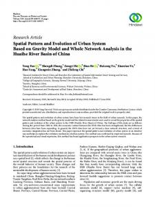
Research Article Web Based Security System Genesis Ajah1, Nathan David2, Abioye Ayodeji Opeyemi3 1 Undergraduate Project, Department of Electronic Engineering, University of Nigeria, Nsukka. 2Lecturer and Project Supervisor, Department of Electronic Engineering, Faculty of Engineering,University of Nigeria, Nsukka. 3 Department of Electrical and Electronic Engineering,School of Engineering, Modibbo Adama University of Technology (MAUTECH), Yola. *Corresponding author Genesis Ajah Email: Abstract: Security systems play an important role in the protection of lives and investment. The aim of this project is to design an efficient and cheap security system, which is accessible from any part of the world through the internet, and can be employed in every facet of the economy. This is achieved by incorporating various subsystems (such as surveillance, intruder control, access control, fire detection, etc.) into the security system with a single control unit. The conceptual model includes the following modules: Access control unit (Biometrics), Smoke detector unit, Temperature sensor unit, Intruder detector unit, Surveillance unit, Alarm system unit, and Web based monitoring and control unit. The main control unit is a microcontroller which performs real time monitoring and is interfaced with a PC. The PC runs an application that consists of a web based Graphical User Interface (GUI) which displays access characteristics, sensor levels and security status which can be monitored and controlled by an administrator (a human user). Sensory responses, fed to the PC by the microcontroller, is displayed on the web based GUI. The PC application controls access to restricted resources and contains a database of activity and access logs. The security cameras are interfaced to the PC via USB port and transmit over the internet using the TCP/IP protocol. The web-based security system was designed and implemented using simple electronic components, circuits and computer processing power. Keywords: Security, Surveillance, Biometric, Personal Computer (PC), Graphical User Interface (GUI), Control Unit, Computer Application, Web, TCP/IP protocol. INTRODUCTION In the present day, security systems play an important role in the protection of lives and investment. This is achieved by the incorporation of various subsystems into the security system with a single control unit such as surveillance, intruder control, access control, fire detection, etc. The aim of this project is to design an efficient, cheap security system accessible from any part of the world through the internet that can be employed in every facet of the economy. The conceptual model is shown in Figure 1 and includes the following modules (i) access control unit (Biometrics), (ii) smoke detector unit, (iii) temperature sensor unit, (iv) Intruder detector unit, (v) surveillance unit, (vi) Alarm system unit, (vii) web based monitoring and control unit. The access control subsystem (entry authentication) is of the iris biometric authentication. The sensors employed in the other subsystems are generally cheap but efficient. A microcontroller forms the main control unit which performs real time monitoring and is interfaced with a PC. The PC runs an application that consists of a web based Graphical User Interface (GUI) which displays access characteristics, sensor levels and security status which can be
monitored and controlled by an administrator (a human user). All sensory response is fed by the microcontroller to the PC which is then displayed on the web based GUI. The PC application performs the acquisition and authentication of access. It controls access to the various restricted resources and contains a database of activity and access logs. The security cameras are interfaced to the PC viauniversal serial bus (USB) port and transmit over the internetusing the TCP/IP protocol. The web-based security system was designed and implemented using simple electronic components, circuits and computer processing power. METHODOLOGY The methods used at arriving at the final design of the system and the components employed revolve around a compromise between effectiveness, compactness and cost. The main aim of any security system is to provide effective monitoring, access and reactive services. For the purpose of this study, a scaled down model or prototype was designed. The design of the security system takes on an overall top-down modular approach. The two major modules are the hardware module and the software module. Each top module has a defined function and is further divided
112
Ajah et al., Sch. J. Eng. Tech., 2013; 1(3):112-116
into sub-modules which work together to achieve a
specified goal.
Figure 1: Conceptual model of security system Hardware Module Organization The hardware module was designed to consist of the following units Intrusion detector unit: A pyroelectric infrared sensor [1,2] is used for our intrusion detection, it hasa higher degree of detection than other intrusion detectors like photoelectric beam sensors and infrared sensors [3]. The pyroelectric sensors exhibit high sensitivity and reliable performance. Temperature sensor unit: The LM35 [4] is used. The LM35 is a precision integrated circuit temperature sensor whose output is linearly proportional to the Celsius (Centigrade) temperature. The LM35 does not require any external calibration or trimming to provide typical accuracies of ±¼ ºC at room temperature and ±¾ ºC over a full -55 to +150ºC temperature range. Low cost is assured by trimming and calibration at the wafer level. The LM35’s low output impedance, linear output, and precise inherent calibration make interfacing to readout or control circuitry especially easy. As it draws only 60μA from its supply, it has very low self-heating, less than 0.1 ºC in still air. The LM 35 is cheap and has a wider range of measurement than LM 34, LM 56, and LM 75 [5]. Smoke sensor unit: The MC145012 CMOS IC [6] is the smoke sensor used. It is a smoke detector (photoelectric detector) component containing sophisticated very low-power analog and digital circuitry. Detection on this device is accomplished using IR (photodiodes) detectors that are directly
interfaced to the CMOS IC to sense the presence of scattered light. Smoke particles help in scattering light thereby allowing light to fall on the photodiode and activating it. The photodiode is connected to a comparator circuit which gives a signal if the threshold value is exceeded. The threshold is variable hence the smoke sensor has adjustable sensitivity. Surveillance unit: Internet Protocol (IP) cameras are used for surveillance. These cameras provide video recording and playback at a lower resolution and frame rate than the security camera. IP cameras are typically for video transmission over the internet/intranet. However, the video is channeled to the PC GUI. Analysis isn’t carried out by the external hardware module but is done by specialized graphics hardware in the PC. Hence, the IP camera links bypass the external hardware and is connected directly to the network switch. The IP camera software is integrated into the PC web based GUI for Compactness of the model system. Encoder and decoder unit: The RF 600Dand RF600E [7] were chosen because of the high security level built into both ICs. This is because the RF600D can only decode information encoded by an RF600E it already knows about. The RF600E requires first external switches to be able to encode four channel signals into a serial string of codes. The encoder provide a serial input of six words for hard wired, infrared or fibre optic communication links. Channel adds logic is provided to control the 113
Ajah et al., Sch. J. Eng. Tech., 2013; 1(3):112-116
number of encoded channels from three to six, allowing increased design flexibility. Transmitter and receiver unit: An AM hybrid transmitter module (AM-RT4-433) [8] is a complete transmitter on a board without a need for external components. It operates in the free frequency range of 433MHz unlike some other transmitters that like AM-88 and AM-25that transmit at medium wave (530-1710 kHz) and a long wave (150-285 KHz). It has a very high frequency stability hence eliminating the possibility of frequency drifts during operation. It is not expensive and therefore, it was used. The model is very simple to operate and offers a low current consumption. These modules show very high frequency stability over a wide operating temperature even when subjected to mechanical vibrations. The data processing unit: The data processing unit functions as the central monitoring unit and PC interfacing unit for the hardware model. The unit continuously scans the other connected submodules for signals which are then organized and sent to the PC through an interface [9]. Atmel AT89C51 microcontroller [10] is employed here. The choice of this chip is based on cost, availability of development tools and familiarity with the instruction set. The Interface unit: The computer standard parallel port (LPT1) is chosen to serve as the interface between the PC GUI application and the microcontroller monitored hardware. It is chosen because of its relative ease of transmission and reception of data compared to that of the serial port [11]. Moreover the standard parallel has been optimized for hardware and digital logic interfacing [12]. The standard parallel port serves as the channel for transferring data from the hardware module to the software module. The Power supply unit: A simple power supply unit constructed from basic and readily available ICs would have been ideal. However, since the unit operates with a PC interface, a battery-powered supply unit is unnecessary as there has to be ac
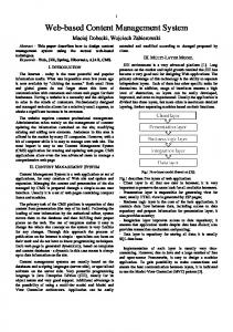
mains supply for the PC to operate. A readily available variable dc adapter is therefore employed for the hardware module. Software Module Organization The PC interface application software should possess the following capabilities: Ability to handle data collection from microcontroller based security system; logging of access times Ability to integrate security camera hardware module and display video Audio-visual representation of ingress and egress with access control system Virtual instrumentation for sensors/transducers and audiovisual alert upon triggering Based on these functions, the software is divided into modules which interact using a top-down, object oriented design approach. This modular application was designed optimally using a programming language that has the following characteristics: (i) Object Orientation, (ii)Feature for port interfacing, (iii) Network capability, and (iv) Web based GUI mode. The Microsoft ASP.NET programming language is used since it possesses all the aforementioned characteristics and the designers are proficient in its use. However, being more web and network driven, the port interfacing extension capability is optimized using drivers written in C# language. ASP.NET employs the .NET framework IDE suite which is a complete suite of tools for building both desktop and team-based Enterprise Web applications [13]. Circuit Operation Information from the sensors in the hardware sub modules were encoded and transmitted wirelessly to the receiving circuit interfaced with the computer. The decoder on the receiving circuit extracts the original information from the received signals for each of the sensors and sends it to the microcontroller for processing, the block diagram of the microcontroller unit connection is shown in Figure 2. The system was tested.
Figure 2: Microcontroller connection design for security system 114
Ajah et al., Sch. J. Eng. Tech., 2013; 1(3):112-116
The access control unit employs Iris biometric authentication interfaced with the microcontroller. On activation, the data is sent to the PC via the interface; the PC application then checks the validity and identity of the user and grants access to the bearer. The smoke detector unit employs scatter-type photoelectric smoke detectors which consist of a linear arrangement of an infrared emitter diode (IRED transmitter) and an infrared detector diode (receiver) in a detection chamber. With increase in smoke levels in the detection chamber, scattering of light occurs and light reaches the infrared detector thereby varying its resistance. This resistance is compared against a fixed value and on activation, a signal is sent to the microcontroller unit which in turn activates the alarm circuit sends the info to the PC for display. The temperature sensor unit is used as a fire detection control in this project. The sensor employs is a simple IC which changes internal resistance with temperature change. This resistance is compared against a fixed value and on activation, a signal is sent to the PC via the microcontroller. The alarm circuit is also activated. The intruder unit is a made of a human emitted infrared detector device. Interruption of the pyroelectric beam, even for a very short interval, sends a signal to the PC application via the microcontroller and activates an alarm. The surveillance unit for this project employs the use of internet protocol cameras for use in the surveillance system a Video signal is fed directly to the monitoring units which is integrated into the web based monitoring system and can be monitored by the PC security application.The alarm system unit makes use of a simple buzzer for audio alert in case any detector is triggered. The PC central monitoring unit is entirely software based and forms the control and display unit of the entire security system. Detectors are monitored via the display. Access control can be monitored and access logs stored on its database. This information (software and database) is available online and can be controlled from any internet-enabled computer. DISCUSSION The electronics workshop, university of Nigeria was made available for implementation and execution of this project. Challenges were encountered in the course of this study, some were apparent from the onset but were tackled as they became evident. Some encountered challenges are discussed below: Windows XP port security feature – It was discovered that all Windows NT based operating systems have a security feature which restrict access to its port from user level. A Dynamic Link Library (DLL) was used to bypass this feature and grant system level port access. The DLL, inpout32.dllis a freeware which was downloaded from the Internet and inserted in the Windows system directory. This DLL is called from the PC GUI to grant access to the parallel port [14].
GUI memory usage – Due to the nature of the software application, which performs continuous loop operations while handling other events, the memory required by the application is quite large (∼20MB). This slows down the application considerably. Even though this could not be changed, the visible effects were reduced by employing a host PC with a large amount of RAM and a high speed processor. Hardware module restriction – At various stages of the hardware design, the hardware failed. This is consistent with pre-etched board circuits. These failures were overcome by troubleshooting the circuit. At the completion of the hardware design, it was also discovered that the hardware needed to be reset each time a connect status bit was to be sent to the PC. This could not be resolved so a manual reset was employed as needed during testing and demonstration. Access to paid-online information – come crucial information required for ease of implementation were online for a price, as at time of project execution, accessing this facility was difficult. Time – this was the most challenging aspect of the project. The planned timeline for completion of sub tasks and the schedule for the final roll out of the design was disrupted due to unforeseen circumstances such as prolonged power outages, difficulty in finding replacement for faulty, damaged or burnt components, unavailability of specialized equipment to perform certain tasks.
The summary of the project expenditure is listed below in Nigerian naira: Software development package expense N 25,000:00 Hardware component expenses N 18,580:00 IP camera purchase N 50,000:00 Miscellaneous N 8,000:00 TOTAL N101,580:00 All the resources were obtained locally except for the intrusion detector, Murata IRA-E700 Pyroelectric Infrared sensor, and the Atmel AT89C51 microcontroller which were imported from outside the country. Indigenous knowledge was employed with no prior trainings of persons involved, outside the university. CONCLUSION The security system was designed to be a simple model showing possible incorporation and integration of different security systems into a single unit with central monitoring. Based on this objective, the design was restricted by economic and spatial factors. With this in mind, it is adequate to say that the project responded acceptably. 115
Ajah et al., Sch. J. Eng. Tech., 2013; 1(3):112-116
This project is an upgradeable model. However, its functionality was restricted due to certain limitations. Possible upgrades or enhancements of the model include: Universal Serial Bus (USB) port interfacing – although more complex than the parallel port, USB has the advantage of being fast and convenient. Moreover, with the parallel port slowing becoming obsolete in the new technological era, the USB port has to be embraced. More secure access card system – the use of a more sophisticated and efficient card system to reduce or eliminate forgery and false authentication. Programmable Logic Devices (PLD) – The use of PLDs to replace the Transistor-Transistor Logic (TTL) employed in the hardware circuit. This increases the circuit capability and reduces the space required (a circuit consisting of many TTL ICs can be programmed on a single PLD) as well as development time. Incorporation of more security subsystems – other security systems can be added to the central monitoring unit. These systems could include fingerprint authentication systems, production control systems, voice recognition systems, etc.s References 1. Murata. 2012; www.murata.com. [Online]. www.murata.com/products/catalog/pdf/s21e.p df 2. Moghavvemi M, Lu CS, Pyroelectric infrared sensor for intruder detection, in Proc. TENCON,2004; 656-659. 3. Chowdhury ZI, Imtiaz MM, Azam MM, R.A. Sumi, and N.S. Nur, "Design and Implementation of Pyroelectric Infrared Sensor Based Security System Using Microcontroller," in Proceeding of the 2011
4.
5.
6.
7.
8.
9. 10. 11. 12. 13.
14.
15.
IEEE Students' Technology Symposium., lIT Kharagpur, 2011, pp. 1-5. National Semiconductor. 2000, www.national.com. [Online]. http://www.ti.com/lit/ds/symlink/lm35.pdf Lacanette K, Silicon Temperatrue Sesors: Theory and Applications, Measurement and Control, 1996;120-126. Freescale Semiconductor. 2006; www.freescale.com. [Online]. http://pdf.zener.ru/123316.pdf?datasheet%20F reescale%20Semiconductor%20MC145012EG R2 R.F. Solutions. 2004; RF / IR Encoder / Decoder Chipset RF Evaluation Boards. [Online]. http://docseurope.electrocomponents.com/webdocs/059f/ 0900766b8059fddd.pdf R.F. Solutions. 1999; www.rfsolutions.co.uk. [Online]. http://www.maplin.co.uk/Media/PDFs/vy48.pd f Axelson J, The Microcontroller Idea Book. Madison: Lakeview Research, 1997. ATMEL. 2000; www.atmel.com. [Online]. http://www.atmel.com/images/doc0265.pdf Scherz P, Practical Electronics for Inventors. New York: Mc-Graw Hill, 2000. Hall DV, Microprocesors and Interfacing, 2nd ed. New Delhi: Tata Mc-Graw Hill, 2004. Himpe V, Visual Basic for Electronics Engineering Applications., 3rd ed.: Elektor International Media, 2006. Axelson J, Parallel Port Complete: Programming, Interfacing, & Using the PC's Parallel Printer Port., New edition ed.: Lakeview Research, 1997. Find Later. Axis Network Cameras. [Online]. www.axis.com/files/brochure/bc_netcams_346 90_en_0903_lo.pdf
116