Jestr
JOURNAL OF
Journal of Engineering Science and Technology Review 6 (1) (2013) 129 - 133
Research Article
Engineering Science and Technology Review www.jestr.org
Research on Function Structure Inverse Solving Method of Design History based on S-S-E-F Mapping Shaofei Jiang*, Jianhui Shao and Jiquan Li Key Laboratory of Special Purpose Equipment and Advanced Processing Technology, Zhejiang University of Technology, Ministry of Education, Hangzhou 310014, China Received 15 May 2013; Accepted 25 July 2013
___________________________________________________________________________________________ Abstract Most enterprises have deficiencies in the information management of available product design history, which causes unable to directly identify the corresponding relation between structure and function, so the true local demand-varying design can't be really realized. To rapidly and efficiently solve the local demand-varying design, this study proposes the use of Structure-Solution-Effect-Function (S-S-E-F) mapping-based inverse method to solve the function structure of design history. The function structure of design history is obtained by constructing the inverse solving model of design history based on S-S-E-F mapping, then capture product design intent information .Moreover, the feasibility of the proposed method is verified by analyzing the function structure of forklift drive axle as an example. Keywords: Structure-Solution-Effect-Function (S-S-E-F), function structure, design intent, inverse solving, local demand-varying
__________________________________________________________________________________________ 1. Introduction Local demand-varying design, such as the generally accepted adaptive design and the variant design, occupies an important position in the field of product design. In local demand-varying design, most previous studies skipped function to resolve the demand-varying response issue by directly imitating or modifying the original structure. However, the function of product is directly related to the demands, modifying the structure of product can only implement simple imitation of others’ design results, then the characteristics of existing product can't be thoroughly understood, the original design intent can't be also read, so the local demand-varying design can't be really achieved from the source. Since most enterprises have deficiencies in the information management of referential product design history, there is the missing of data, process, decisionmaking basis, and design intent in different degree, which causes unable to directly identify the corresponding relation between structure and function. To achieve the real demandvarying design, the real design intent of the original designer must be obtained by reversing product function structure and identifying the corresponding relationship between structure and function of design history. Then some parts of design history can be really transplanted to the new product when the designer understands the intent of the original design. So, identifying the corresponding relation between structure and function of design history by the Structure-Solution-EffectFunction mapping is the fundamental basis to realize local ______________ * E-mail address:
[email protected] ISSN: 1791-2377 © 2013 Kavala Institute of Technology. All rights reserved.
demand-varying design. This paper proposes the use of S-S-E-F mapping-based inverse method to solve the function structure of design history , it starts from the product design history structure to gradually obtain the function structure of design history, which provides a good support for local demand-varying design. 2. Relevant Research 2.1 Traditional process of conceptual design Product design based on functional requirements as a starting point is a solving process which searches function structure scheme. At present, the typical mapping solving process model are as follows: the function-structure direct mapping model[1]; the function-behavior-structure mapping model[2-4]; the function - behavior - state mapping model[5]; the function-carrier mapping model[6-7]; the function-effect- solution mapping model[8]; Function modelling is a typical forward solving process that can only start from the function and then gradually find the design solution. These mapping solving models are suitable for a completely innovative design, but they cannot solve the inverse solving of the function structure in local demandvarying designs. 2.2 Research on the design intent capture According to different sources, the design intent can be divided into two types. The first type refers to a designer’s purpose, decision, and design basis during the design. The second type refers to the intent of the designer implied in the design process. Most existing design intent capture methods
Shaofei Jiang, Jianhui Shao and Jiquan Li/Journal of Engineering Science and Technology Review 6 (1) (2013) 129 - 133
formally express design intents by modeling. Yoko Ishino et al.[9] defined the design intent as the design standard and scale decided by the designer during the design process to complete the entire design, to construct the intent estimation model of the design process, and to capture the design intent by determining the weighting function of various performances. X William Xu et al.[10] defined design intent as the constraints and goals defined by the designers in computer-aided design (CAD) and the optimal design solution obtained through behavioral modeling to capture the design intent and to make repeated comparisons on the design results in accordance with the design intent. Ming Li et al.[11] proposed a new method for capturing the design intent by using symmetry in the approximated CAD model. Most recent studies on design intent capture have been conducted with the design process. Such design intent capture cannot effectively support the re-excavation of the design intent of the original products in the process of local demand-varying design. The inverse method proposed in this paper based on S-S-E-F mapping provides a better support for the re-excavation of the design history intent in local demand-varying design.
3.1 The inverse solving method of structure to solution Effect is generated for some reasons, which produces a particular scientific phenomena, and realizes the corresponding function by the principles prescribed by the law that changes input flows into output flows[12].If the discrete effects are organized into an effect base, a function can be mapped to a solution by using the effect base in the innovation design. And in local demand-varying design, according to the input/output flows of the product structure, retrieve the effect in the effect base, the effect or effect group embodied in the carrier can be obtained. Accordingly, building a scientific and reasonable effect base is the key to solve the above problem. A effect base is builded in this paper. It mainly involves the following parameters: the effect number, effect name, the function that can be achieved by effect, the input/output flows of effect, an engineering example. Figure 2 shows the fragment of effect base. engineering example
effect effect effect effect function input output number definition transmit friction power force force E11 effect transmit torque ……
3. Modeling for the Inverse Solving Process
E23
The mapping from structure to function is a very important process, in this process, it needs to analyze the original design intent to obtain the real function structure model. Shown in Figure 1, this paper puts forward the inverse solving process model based on structure - function mapping. According to the existing products structure, analyze and sort out the product structure model; Then introduce the input/output flows into the product structure model; Using the input/output flows of each structure as a retrieval condition to retrieve the effect in effect base, then the solution corresponding to each structure can be obtained, thus, the product structure model can be inverse solved to the solution model of design history. The solution contains its own effect, the function unit corresponding to the effect can be obtained by retrieving the effect base. Combine function unit to produce child function, thus the regeneration of the original function structure can be realized.
force leverage magnify force effect power distance distance
Fig. 2. Fragment of Effect Base
A specific product is composed of a group of components and a number of connections. Structure shows its bearing function effect through certain actions under certain environmental conditions. Product structures convert or transfer energy, material and information flows by certain behaviors to achieve the desired function. To get the solutions of product, the energy, material and signal flows converted or transfered by product structure should be introduced into the product structure model, and then the solutions of design history can be obtained under the support of effect base. Figure 3 shows that the solution structure of design history is obtained when introducing the input\output flows into the product structure model and retrieve the effect in the effect base. product
8
component
parts
1
feature
component
product structure model
。。。
component
parts
。。。
5
7
5
parts parts
feature
feature
4
8
1
4
4 。。。
2
connection
parts
parts
7
8
effect base
5
1
E2
。。。
8
E5
6
E6
E4
parts
4
parts
E9
E7
(1,2,3,…,8)
。。。
energy flows
2
extract effect
signal flows connection
7
3
connection
。。。
connection
material flows
8
3
solution
5 4
6
2 2
4
4
assembly connection type
2
3
8 component
component
structure (1,2,3,…,8) assembly connection type
1
5
E
E8 7
3 1
7
import input\output into the product structure model
structure
4
E3
feature
product structure model
parts
product structure decomposition tree
connection 6
2
E1
feature
feature
4
3
energy flows signal flows
2
feature
3 5
parts
introduce input\output flows
material flows 8
3
3 5
4 solution structure structure — function inverse solving process
。。。
component
parts
parts
structure (1,2,3,…,8) assembly connection type
5
component
parts
。。。
5
component
6 parts
1
4
8
2 2
parts
feature
component
3
parts
4
3
4
8
component
product
5
2
structure
6 4
2
basic flows
effect structure
retrieve the effect in the effect base
effect
function units structure
function structure
effect base
。 。 。
8
4
material flows
。 。 。
5
energy flows signal flows
1
function units
。 。 。 。 。 。
material flows
combine function units
。。。 3
energy flows
solution
7
3 1
6
(1,2,3,…,8) assembly connection type
2
5 4
signal flows child function
product solution structure
Fig. 3. The Inverse Solving Process of Structure to Solution
Fig. 1. Voltage Stabilizer Block Diagrem 130
connection
Shaofei Jiang, Jianhui Shao and Jiquan Li/Journal of Engineering Science and Technology Review 6 (1) (2013) 129 - 133 。 。 。
3.2 The inverse solving method of solution to effect After the inverse solving of structure to solution, the solution structure of design history can be obtained. The solution consists of a effect or effect group and the necessary geometrical and material characteristics added to the effect[13]. To solve the effect structure of design history, the geometrical and material characteristics in every solution should be removed ,then extract the corresponding effect or effect group in the solution. According to the corresponding position of each solution in the solution structure, arrange each effect extracted from the solution, then the effect structure of design history can be obtained. Figure 4 shows the process that the solution structure of design history is reversed into the effect structure of design history.
。 。 。 effect
。 。 。
5 1
。 。 。 。 。 。
6
function units
material flows energy flows signal flows child function
function structure
4. Example Validation
(1,2,3,…,8) assembly connection type
2
3
solution
7
1
signal flows function units structure
Fig. 5. The Inverse Solving Process of Effect to Function
3
。。。
material flows energy flows
。 。 。
8
4
basic flows effect structure
retrieve the function unit in the effect base
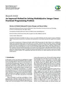
Forklift drive axle is at the bottom of forklift driving system, its basic function is increasing the torque transmitted from drive shaft, allocating the power to the left and right driving wheels, and making the left and right driving wheels have the differential function required by kinematics. At the same time, drive axle also bears vertical force and horizontal force applying to the road surface and the frame of forklift[15]. The forklift drive axle is mainly composed of the main reducer, differential , half shaft, shell, etc. Figure 6 shows the forklift drive axle structure diagram.
5 4
connection
product solution structure
Remove the geometry and material characteristics of solution, extract the effect in the solution, according to the solution structure, combine the extracted effect. 。 。 。 。 。 。
1
effect
basic flows
2
product effect structure
3
Fig. 4. The Inverse Solving Process of Solution to Effect
6 4
3.3 The inverse solving method of effect to function After getting the effect structure of design history, retrieve each effect of the effect structure in effect base, then each effect can get its relevant function unit. According to the corresponding position of each effect in the effect structure, arrange each function unit, then the function unit structure of design history can be obtained. The total function of product is generally composed of several child functions, each child function can be divided into a number of discernible point function which respectively corresponds to several structure module of the entire product. Function structure is meaningfully, compatibly linked up by point functions[14]. The function units retrieved from the effect base are in the bottom of the functional decomposition tree, which can no longer be further decomposed. These function units can not provide strong support for designers to capture product design intent in the subsequent product design, so they should be further processed. The complete function structure model of product is obtained by aggregated the function units. Figure 5 shows the process that the effect structure of product is reversed into the function units structure of product, then the function units structure of product is reversed into the function structure.
5
7 9 8
Fig. 6. Forklift Drive Axle Structure 1-drive shaft 2-drive bevel gear 4- differential shell 7-half shaft gear
5-spider 8-half shaft
3-driven bevel gear 6-planetary gear 9-shell
Because the design history management in existing forklift enterprises does not reach the designated position, the data, design process, decision-making basis and design intent involved in the process of designing forklift drive axle are not be recorded or little be recorded, it is hard to distinguish corresponding relation between the structure and function information in the design of forklift. In order to 131
Shaofei Jiang, Jianhui Shao and Jiquan Li/Journal of Engineering Science and Technology Review 6 (1) (2013) 129 - 133
solve the problem that the forklift design history management does not reach the designated position, the inverse solving method proposed above can be used to distinguish the corresponding relationship between the structure and function of forklift drive axle.
torque\speed torque torque\speed energy energy torque\speed balance\ conservation conservation torque transmit differential\ 8 8 8 main reducer drive shaft half shaft differential
force
4.1 The solving of drive axle structure model to solution structure
drive bevel gear
drive shaft
torque speed
feature fusion
cylindrical roller bearing
driven bevel gear
ring r bea l rolle drica cylin
half shaft gear
spider
shell
tapered roller bearing
hub
bolt connection
differenti -al shell
spline half connection
half shaft gear
shaft
tor
qu e \s
pe e
torque\speed
d
shape connection
spider structure
gear
driven bevel gear
torque\speed
torque\speed differenti -al shell
spider
force
half shaft
basic flow
torque\speed
half shaft gear
torque\speed
connection
planetay gear
energy flow
torque speed
energy conservation
torque speed
torque balance torque speed
energy conservation
force
Newton's law shell
1
\spe torque
forklift drive axle solution structure
energy conservation hub ed
to rq ue \
8
1
force
torque
torque speed
transmit
torque speed
torque speed energy conservation
differential solution
force
sp ee
d
torque\speed torque torque\speed energy energy torque\speed Balance\ conservation conservation torque transmit Differential\ 8 8 8 Main reducer drive shaft half shaft differential
1
torque speed energy conservation
force
energy conservation
retrieve effect base torque\speed
torque speed
structure torque\ speed
torque\speed
hub
torque transmit
torque speed
After getting the effect structure of drive axle, retrieve each effect of the effect structure in effect base, then each effect can get its relevant function unit. According to the corresponding position of each effect in the effect structure, arrange each function unit, then the function unit structure of drive axle can be obtained. Aggregate some functions units in the function units structure of drive axle, then The complete function structure model of drive axle is obtained. Figure 9 shows the process that the effect structure of drive axle is reversed into the function units structure of drive axle, the function units structure of drive axle is reversed into the function structure of drive axle.
connection gear surface assembly planetay
force
force shell
energy conservation
Fig. 8. The Inverse Solving Process of Drive Axle Solution Structure to Effect Structure
forklift drive axle structure model
drive bevel gear
torque balance torque speed
effect
import input\output torque\speed drive shaft
assembly connection type
forklift drive axle effect structure
differenti -al shell
Sliding bearing
flange connection
energy conservation
torque speed
force
differe -ntial
hub
planetay gear
gear surface assembly
drive bevel gear
energy flow
(1,2,3,…,8)
differential
forklift drive axle decomposition tree
drive shaft
connection
4.3 The solving of drive axle effect structure to function structure
half shaft
driven bevel gear
Newton's law shell
energy 1 conservation hub d e e p e\s torqu
Remove the geometry and material characteristics of solution, extract the effect in solution, according to the solution structure, combine the extracted effect.
forklift drive axle
shell
force
forklift drive axle solution structure
In order to solve the solution structure of drive axle, the drive axle should be dismantled into the drive axle decomposition tree, then connect the structure at the decomposition tree with assembly connections, finally the structure model of drive axle can be got. Introduce the energy, material and signal flows that the drive axle structure convert or transfer into the structure model of the drive axle, each solution corresponding to each structure can be obtained by retrieving the effect base. According to the corresponding position of each structure in the structure model , arrange each solution , thus the solution structure of drive axle can be obtained. Figure 7 shows the process that the structure model of drive axle is reversed into the solution structure of drive axle.
main reducer
solution
8
1 1
to rq ue \s pe e
d
torque\speed
connection
force
energy conservation
effect basic flow forklift drive axle effect structure
energy flow
(1,2,3,…,8)
retrieve effect base
assembly connection type
Fig. 7. The Inverse Solving Process of Drive Axle Structure Model to Solution Structure
torque speed
input torque
4.2 The solving of drive axle solution structure to effect structure
torque speed
reduce Speed
torque speed
increase torque holding power
distribute torque
torque speed
distribute speed hold power transmission device
transmit torque
torque speed
output torque
torque speed
holding power
forklift drive axle function units structure
The solution consists of a effect or effect group and the necessary geometrical and material characteristics added to the effect. To solve the effect structure of drive axle, the geometrical and material characteristics of every solution in the solution structure of drive axle should be removed , then extract the corresponding effect or effect group in the solution of drive axle. According to the corresponding position of each solution in the solution structure, arrange each effect extracted from the solution, then the effect structure of drive axle can be obtained. Figure 8 shows the process that the solution structure of drive axle is reversed into the effect structure of drive axle.
Combine function units torque speed
input torque
torque speed
reduce Speed increase torque
torque speed
provide different -ial
torque speed
transmit torque
torque speed
output torque
torque speed
hold holding power power transmission device forklift drive axle function structure
holding power
Fig. 9. The Inverse Solving Process of Drive Axle Effect Structure to Function Structure
132
Shaofei Jiang, Jianhui Shao and Jiquan Li/Journal of Engineering Science and Technology Review 6 (1) (2013) 129 - 133
identify the corresponding relationship between product structure model and function structure. (3) Building a scientific and reasonable effects base is the basis and premise to realize the inverse solving of function structure of design history.
5. Conclusions
(1) The function structure inverse solving method of design history based on S-S-E-F mapping can be used to realize the inverse solving of the product structure model to the function structure, and the original design intent can also be captured. Acknowledgements (2) The example of forklift drive axle explains that the This project is supported by National Natural Science function structure inverse solving method of design history Foundation of China (Grant No. 51005211). based on S-S-E-F mapping has a certain auxiliary effect to ______________________________ References 1.
2. 3.
4.
5.
6.
7.
FENG P-e, XU G-r, ZHANG M-j, “Feature modeling based on design catalogues for principle conceptual design”, AI EdamArtificial Intelligence for Engineering Design Analysis and Manufacturing 10(4) , 1996, pp. 347-354. Gero J. S., Kannengiesser U., “The situated function–behaviour– structure framework”, Design Studies 25(4), 2004, pp.373–391. Yuxin Wang, Xuguang Zhang, Xiaohui Mao, “Implementation and Quotient Representation of Creativity in Functional Layer and Form Layer of the Function-behavior-structure Model”, Journal of Mechanical Engineering 46(15) ,2010, pp. 107-116. Bergen Helms, Kristina Shea, Frank Hoisl, “A framework for computational design synthesis based on graph-grammars and function-behavior-structure”,Proceedings of the ASME 2009 International Design Engineering Technical Conferences & Computers and Information in Engineering Conference,2009, pp. 111. Umeda Y., Kondoh S., Shimomura Y, et al, “Development of design methodology for upgradable products based on functionbehavior-state modelling”, AI Edam-Artificial Intelligence for Engineering Design Analysis and Manufacturing 19(3), 2005, pp. 161-182. SUH N. P., “Axiomatic design: advances and applications”, Oxford University Press, 2001.
8.
9. 10. 11. 12. 13. 14. 15.
133
SUH N. P., “The principles of design”, Oxford University Press, 1990. Peien Feng, Shuai Zhang, Shuangxia Pan, “Cyclic Solving Process and Realization for Conceptual Design of Complex Function Product”, journal of Mechanical Engineering 18 (3) ,2005, pp.135141. Ishino Y., YAN J., “Estimate design intent: a multiple genetic programming and multivariate analysis based approach”,Advanced Engineering Informatics 16(2), 2002, pp.107-125. Xu X. W., Galloway R., “Using behavioral modeling technology to capture designer's intent”, Computers in Human Behavior 21(2),2005, pp.395-405. Li M., Langbein F. C., Martin R. R. , “Detecting design intent in approximate CAD models using symmetry”, Computer-Aided Design 42(3), 2010, pp.183-201. Runhua Tan, “Innovative Design — TRIZ : Invention Problem Solving Theory ”,Beijing: Mechanical Industry Press, 2002. BEITZ G, PAHL W, “Engineering Design ”,Beijing:Mechanical Industry Press, 1992. Zhongyuan Dong, Kezhu Jiang, “Design Methodology ”, Higher Education Press, 1991. Yuanfang Tao , Liangbao Wei, “Forklift Construction and Design”, Mechanical Industry Press, 2011.