Hindawi Publishing Corporation Mathematical Problems in Engineering Volume 2014, Article ID 237131, 11 pages http://dx.doi.org/10.1155/2014/237131
Research Article Resizing Technique-Based Hybrid Genetic Algorithm for Optimal Drift Design of Multistory Steel Frame Buildings Hyo Seon Park,1,2 Eunmi Kwon,3 Yousok Kim,2 and Se Woon Choi4 1
Department of Architectural Engineering, Yonsei University, Seoul 120-749, Republic of Korea Center for Structural Health Care Technology in Building, Yonsei University, Seoul 120-749, Republic of Korea 3 Design Department, TSEC Group, Seoul 133-120, Republic of Korea 4 Department of Architecture, Catholic University of Daegu, Gyeongsan-si 712-702, Republic of Korea 2
Correspondence should be addressed to Se Woon Choi;
[email protected] Received 17 October 2013; Accepted 8 April 2014; Published 6 May 2014 Academic Editor: Stefano Lenci Copyright © 2014 Hyo Seon Park et al. This is an open access article distributed under the Creative Commons Attribution License, which permits unrestricted use, distribution, and reproduction in any medium, provided the original work is properly cited. Since genetic algorithm-based optimization methods are computationally expensive for practical use in the field of structural optimization, a resizing technique-based hybrid genetic algorithm for the drift design of multistory steel frame buildings is proposed to increase the convergence speed of genetic algorithms. To reduce the number of structural analyses required for the convergence, a genetic algorithm is combined with a resizing technique that is an efficient optimal technique to control the drift of buildings without the repetitive structural analysis. The resizing technique-based hybrid genetic algorithm proposed in this paper is applied to the minimum weight design of three steel frame buildings. To evaluate the performance of the algorithm, optimum weights, computational times, and generation numbers from the proposed algorithm are compared with those from a genetic algorithm. Based on the comparisons, it is concluded that the hybrid genetic algorithm shows clear improvements in convergence properties.
1. Introduction Genetic algorithms (GAs) are a type of evolutionary computation algorithm that exhibits excellent capability in finding the global optimal solution [1–4] and have been applied to various research fields [5–11]. The basic principle of GA is to find the optimal solution with the highest fitness using repeated computation [12]. However, one of the limitations of using GAs is the long computation time since the number of required iterations for convergence is relatively large. For structural optimizations, the structural analysis must be repeated many times, and the required computation time for convergence is also large [13]. An additional limitation of GAs is that the global optimal solution may not be found if early convergence occurs for a local optimal solution [14]. Hybrid GA (HGA) techniques with various local search techniques have been studied to improve the convergence speed and optimal solution search technique of GAs [12, 15]. The HGA techniques that are combined with other techniques include the distributed hybrid algorithm-based
GA [16], the Tabu search technique-based GA [17], the optimal criteria technique-based GA [18, 19], and the Taguchi technique-based GA [20]. These HGA techniques can be applied to a wide variety of problems; however, they cannot provide the fundamental solutions to the improvement of the convergence speed because they require complicated sensitivity analysis of structures or reiterated computations in addition to the structural analysis. On the other hand, in the drift design based on resizing techniques, the active members with a relatively high influence on the magnitude of the lateral displacement to be controlled are selected and the cross-sectional properties of the active members are resized or controlled without any iterative structural analysis or sensitivity analysis [21]. The active members are identified by the displacement participation factors defined by each member’s contribution to the displacement. Required information for the calculation of displacement participation factors include the stress resultants due to the actual load and the unit load. The stress resultants due to the actual loads are available in
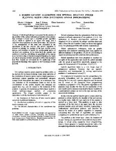
Mathematical Problems in Engineering Constraint ratio
2
Range using resizing technique
Violated
Upper limit Range without the application of resizing technique
Lower limit
Satisfied Range using resizing technique Individual
Figure 1: Illustration of the application range of the resizing technique according to the constraint ratio.
conventional optimization or design process for calculation of load-carrying capacities of a structure. Additional calculations required for displacement participation factors are stress resultants for a unit load. Thus, the resizing technique is an optimal drift design technique that requires neither sensitivity analysis nor repeated structural analysis [22, 23]. However, because the effect of resizing technique heavily depends on the assumed initial design, the resizing technique for the optimal drift design is not useful in the global exploration but is efficient as the local search operator. Therefore, in this study, a resizing technique-based HGA for the optimal drift design of multistory steel frame buildings is proposed to increase the convergence speed of GAs and reduce the number of structural analyses required for convergence of GAs. To improve the convergence speed of the optimal drift design procedure based on the GA, the GA is combined with a resizing technique that does not require repeated or complicated structural analysis, such as sensitivity analysis, and allows for effective control of lateral displacement [21]. In the proposed HGA, the GA and the resizing technique are utilized as the global search algorithm and local search operator, respectively. The resizing technique is adopted in the HGA in two phases. In the first phase, to generate a diverse group of initial individuals (candidate designs), the initial points or designs of GA are presented by applying the resizing technique with the weight control factors in three different ranges to the initial population. In the second phase, to enhance the convergence efficiency, the resizing technique is applied considering the violation ratios of the displacement constraints in each generation. The proposed resizing technique-based HGA is applied to minimum weight design of steel frame buildings. Using three example structures, optimal design results from the resizingbased HGA are compared with the results from conventional GA. To evaluate the performance of the resizing-based HGA, optimum weights, computational times, and generation numbers from the proposed algorithm are compared with those from the GA.
2. GAs for Structural Optimization 2.1. Formulation of Minimum Weight Design. The objective function of this study is set to minimize the sum of the weights of members in a structure, as shown in 𝑚
Minimize 𝑊 = ∑𝜌𝑖 𝐴 𝑖 𝐿 𝑖 ,
(1)
𝑖=1
where 𝜌𝑖 , 𝐴 𝑖 , and 𝐿 𝑖 denote the density, cross-sectional area, and length of the 𝑖th structural member, respectively. 𝑚 is the total number of members in a structure. The structural optimization problem includes the constraints on interstory drift ratio and member strength. The constraint on interstory drift ratio for each story is expressed as follows: 𝑔𝑗 =
𝛿𝑗 /𝐻𝑗 𝑅𝑡
− 1 ≤ 0,
𝑗 = 1 to 𝑛𝑠 ,
(2)
where 𝑔𝑗 denotes the interstory drift ratio constraint at the 𝑗th story and 𝛿𝑗 = Δ 𝑗 − Δ 𝑗−1 . Δ 𝑗 is the lateral displacement at the 𝑗th story. The height of the 𝑗th story is denoted by 𝐻𝑗 , and the limit of the interstory drift ratio is denoted by 𝑅𝑡 (𝑅𝑡 = 1/400 in general). 𝑛𝑠 is the total number of stories in a structure. The constraint on the strength of a member is expressed for the beams as follows: 𝑔𝑘 = (
𝑀𝑢 ) − 1 ≤ 0, 𝜙𝑏 𝑀𝑛
𝑘 = 1, . . . , 𝑚𝐵 ,
(3)
where 𝑔𝑘 denotes the constraint function of the 𝑘th beam and 𝑀𝑢 and 𝑀𝑛 denote the required flexural strength and nominal bending moment, respectively. The AISC-LRFD [24] strength reduction factor of the beam members is 𝜙𝑏 = 0.9, and the number of beam members is 𝑚𝐵 . The constraint function on the strength of the 𝑙th column member 𝑔𝑙 is examined using (4) and (5) depending on the value of 𝑃𝑢 /(𝜙𝑐 𝑃𝑛 ) as follows.
Mathematical Problems in Engineering
3 Start (1) Initial design
(2) Generation of initial population (3) Resizing technique
Phase 1
(4) Structural analysis (5) Constraint evaluation
(6) Fitness evaluation
(7) Selection
(9) Mutation
(8) Crossover (10) Structural analysis and constraint evaluation
No Evolution (selection/crossover/mutation)
Dispallow No
(12)
> upper limit?
Disptop Dispallow
Yes
< lower limit?
(11-1) Resizing technique weight factor = 𝛼
(11-2) Structural analysis and constraint evaluation
Yes
(11-3) Satisfy strength and Disptopfloor ?
(12-1) Resizing technique Disptop Weight factor = Dispallow
Yes
(12-2) Structural analysis and constraint evaluation
No
(11-4) Resizing technique Disptop weight factor = Dispallow
Phase 2
Disptop
(11)
(11-5) Structural analysis and constraint evaluation
(13) Fitness evaluation (14) Fitness comparison and superior individuals preservation No
(15) Convergence? Yes End
Figure 2: Flowchart of the resizing technique-based hybrid genetic algorithm.
If 𝑃𝑢 /𝜙𝑐 𝑃𝑛 ≥ 0.2,
𝑔𝑙 =
otherwise,
𝑀𝑢𝑦 𝑃𝑢 𝑀𝑢𝑥 8 + ( + ) − 1 ≤ 0, 𝜙𝑐 𝑃𝑛 9 𝜙𝑏 𝑀𝑛𝑥 𝜙𝑏 𝑀𝑛𝑦 𝑙 = 1, . . . , 𝑚𝐶;
𝑔𝑙 =
𝑀𝑢𝑦 𝑃𝑢 𝑀𝑢𝑥 +( + ) − 1 ≤ 0, 2𝜙𝑐 𝑃𝑛 𝜙𝑏 𝑀𝑛𝑥 𝜙𝑏 𝑀𝑛𝑦
𝑙 = 1, . . . , 𝑚𝐶, (5)
(4)
where 𝑚𝐶 denotes the total number of columns in the structure, 𝑃𝑢 is the required axial strength, 𝑃𝑛 is the nominal
4
Mathematical Problems in Engineering
3. Resizing Technique-Based HGA
40.86 kN/m
11.12 kN
40.86 kN/m
3.05 m
22.24 kN
40.86 kN/m
3.05 m
3.1. Resizing Technique. In this study, the resizing technique is applied to improve the convergence speed of GA for the optimal drift design procedure. The resizing technique, which is based on energy theory, reduces the lateral displacement of a structure by calculating the displacement participation factors of the individuals for the top-floor displacement using member forces and by resizing the weights of individuals according to the participation factors. Using the unit load method based on energy theory, the lateral displacement in (9) is defined by the sum of the displacement participation factor of members as follows [22]:
3.05 m
22.24 kN 10.97 m
10.97 m
𝑚
Figure 3: Elevation of the three-story example structure.
𝛿 = ∑𝛿𝑖 𝑖=1
axial strength, 𝜙 is the resistance factor (tension = 0.9, compression = 0.9), 𝑀𝑢𝑥 and 𝑀𝑢𝑦 are the required flexural strengths in the 𝑥 and 𝑦 directions, respectively, 𝑀𝑛𝑥 and 𝑀𝑛𝑦 are the nominal flexural strengths in the 𝑥 and 𝑦 directions, respectively (for 2D structures, 𝑀𝑛𝑦 is equal to zero), and Φ𝑏 is the flexural resistance reduction factor (𝜙𝑏 = 0.9). 2.2. Fitness Evaluation. In this study, the penalty function approach as the constraint handling method is employed to transform the constrained problem into the unconstrained problem. The fitness evaluation for the individuals (candidate designs) is expressed in (6), which considers the object function values and constraint violation ratio [25]: Minimize 𝑃 = (1 + ℎ) 𝑊,
(6)
where ℎ denotes the constraint violation ratio of the individual and is expressed as follows: 𝑛𝑠
𝑚𝐵
𝑚𝐶
𝑗=1
𝑘=1
𝑙=1
ℎ = ∑ ℎ𝑗 + ∑ ℎ𝑘 + ∑ℎ𝑙 .
(7)
In (7), ℎ𝑗 , ℎ𝑘 , and ℎ𝑙 denote the constraint violation ratios with respect to the interstory drift ratio and the member strengths of the beam members and column members, respectively. The values of (2)–(5) are divided into three ranges: smaller than zero, between zero and one, and greater than one. Taking the example of ℎ𝑗 in (7) is defined as follows: 0, if 𝑔𝑗 ≤ 0, { { ℎ𝑗 = {𝑔𝑗 , if 0 < 𝑔𝑗 ≤ 1.0, 𝑗 = 1, . . . , 𝑛𝑠 . (8) { 2 {𝑔𝑗 , if 𝑔𝑗 > 1.0, ℎ𝑘 and ℎ𝑙 in (7) are also defined by the same manner as shown in (8). If an individual does not satisfy any constraint condition, the value greater than zero is assigned to the penalty parameter ℎ and the fitness value of the individual becomes greater than the structural weight of the individual as shown in (6). On the other hand, if an individual satisfies all constraint conditions, zero is assigned to the penalty parameter ℎ and the fitness value of the individual becomes the structural weight of the individual. Thus the fitness value of the individuals satisfying all constraint conditions is proportional to the weight of the individuals.
𝑚
𝑙
𝑖=1
0
= ∑ {∫
𝑙 𝑀𝐿 𝑀𝑈 𝑁𝑖𝐿 𝑁𝑖𝑈 𝑑𝑥 + ∫ 𝑖 𝑖 𝑑𝑥 𝐸𝑖 𝐴 𝑖 𝐸𝑖 𝐼𝑖 0
+𝑎∫
𝑙
0
(9)
𝑙 𝑇𝐿 𝑇𝑈 𝑉𝑖𝐿 𝑉𝑖𝑈 𝑑𝑥 + ∫ 𝑖 𝑖 𝑑𝑥} , 𝐺𝑖 𝐴 𝑖 0 𝐺𝑖 𝐼𝑝𝑖
where 𝑁𝑖 , 𝑀𝑖 , 𝑉𝑖 , and 𝑇𝑖 denote the member forces in the 𝑖th member due to axial force, moment, shear force, and torsional forces, respectively. The member forces due to the actual load and the unit load are identified by the superscripts 𝐿 and 𝑈, respectively. 𝐴 𝑖 , 𝐼𝑖 , and 𝐼𝑝𝑖 denote the cross-sectional area, moment of inertia of the area, and moment of inertia of the polar area of the 𝑖th member, respectively. 𝐸𝑖 , 𝐺𝑖 , and 𝑎 denote the elastic modulus, shear modulus, and shape factor of the 𝑖th member, respectively. From (9), the displacement participation factor of the 𝑖th member, 𝛿𝑖 , can be assumed to be reciprocally proportional to the weight of the member. If the weight modification factor that controls the change in weight of each member is defined as 𝛽𝑖 , the objective function of the optimization problem in which the displacement in (9) is to be minimized is expressed as follows: 𝑚
𝛿𝑖 , 𝛽 𝑖=1 𝑖
Minimize
𝛿=∑
Subject to
∑𝜌𝑖 𝐴 𝑖 𝐿 𝑖 = 𝛼∑𝛽𝑖 𝜌𝑖 𝐴 𝑖 𝐿 𝑖 ,
(10)
𝑚
𝑚
𝑖=1
𝑖=1
(11)
where 𝜌, 𝐴, and 𝑙 are the weight density, cross-sectional area, and length of the member. 𝛼 is the weight control factor: the total weight of the structure is unchanged before and after the resizing if 𝛼 is 1.0, decreased if 𝛼 is smaller than 1.0, and increased if 𝛼 is greater than 1.0 during the resizing process. The optimization problem defined in (10) and (11) can be converted to an unconstrained minimization problem using the Lagrange multiplier method. Then, the weight modification factor of each member, 𝛽𝑖 , can be obtained as follows: 𝛽𝑖 = 𝛼√
∑𝑚 𝛿𝑖 𝑖=1 𝜌𝑖 𝐴 𝑖 𝐿 𝑖 . 𝑚 𝜌𝑖 𝐴 𝑖 𝐿 𝑖 ∑𝑖=1 √𝛿𝜌𝑖 𝐴 𝑖 𝐿 𝑖
(12)
Mathematical Problems in Engineering
5 1000
900 880
800
860 820
Time (s)
Weight (kN)
840 800 780
600 400
760 740
200
720 700
0 GA Weight factor 0.9 Weight factor 1.0
GA Weight factor 0.9 Weight factor 1.0
(a) Optimum weight
(b) Computational time
Figure 4: Optimum weights and computational times for Example 1.
40
1400 1200 20
1000 800
0 0
10 Generation
20
Weight Number of individuals using resizing technique (a) Weight factor 1.0
60
1800 1600 Weight (kN)
Weight (kN)
1600
Number of individuals using resizing technique
1800
600
2000
60
40
1400 1200 20
1000 800 600
Number of individuals using resizing technique
2000
0 0
10 Generation
20
Weight Number of individuals using resizing technique (b) Weight factor 0.9
Figure 5: Number of the individuals to which the resizing technique was applied.
The weight modification factor 𝛽𝑖 obtained from (12) is multiplied with the cross-sectional area of the 𝑖th member to resize the weight of the 𝑖th member to minimize the lateral displacement. As a result, each member now has an adjusted cross-sectional area according to the displacement participation factor; thus, they can effectively determine how to control the target lateral displacement of a building [23]. In this manner, the lateral displacement of a building (i.e., the stiffness) is effectively controlled by the resizing technique without repetition of structural analysis. 3.2. Generation of Initial Designs Using the Resizing Technique (Phase 1). In this study, the resizing technique is used to secure various individuals in the initial GA population. At first, in the list of cross sections from which each structural member could choose, the cross sections with the median
cross-sectional area are selected. The structural members within the same group have the same cross sections and the structural members with the different group can have the different cross sections. Then, the initial design in which all members consisting of the structure have the cross sections with the median cross-sectional area from the available cross sections of each member is generated. The initial design is duplicated as many times as the number of individuals (the size of the population) in a GA. All individuals in the population have the same design (the initial design). To secure various individuals in the initial population, the resizing techniques with different values of weight control factors in (11) are applied to duplicated individuals. In this study, the weight control factors, 𝛼, are divided into three different ranges: 0.85-0.95, 0.96–1.05, and 1.06–1.1. The resizing techniques with the same range of factors were applied
6
Mathematical Problems in Engineering 43.78 kN/m
This means that the weight and stiffness of the structure are reduced.
22.24 kN 87.56 kN/m 44.48 kN
3.4. Flowchart of the Resizing Technique-Based HGA. As shown in Figure 2, the HGA is composed of two phases: phase 1, which is the initial setting phase, where the initial population is generated and the fitness is evaluated, and phase 2, where the optimal solution is obtained by repeating the evolutionary procedure. The optimal solution is obtained through the following 15 steps.
87.56 kN/m 44.48 kN 87.56 kN/m 44.48 kN
87.56 kN/m 44.48 kN
[email protected] m
87.56 kN/m 44.48 kN
Step 1. An initial design is generated by using the median cross-sectional area, which is chosen from a list of the members’ cross sections.
87.56 kN/m 44.48 kN
Step 2. An initial design is duplicated 𝑁 times (𝑁 is the number of individuals in the initial population).
87.56 kN/m 44.48 kN 87.56 kN/m
Step 3. The duplicated initial designs are divided into three groups, and the individuals of the initial population are modified by applying the resizing technique using the weight control factors with values in three different ranges.
44.48 kN 87.56 kN/m 4.57 m
44.48 kN
Step 4. Structural analyses are performed with the generated individuals. Step 5. The constraints in (2)–(5) are evaluated using the results from structural analysis.
9.14 m
Figure 6: Elevation of the 10-story example structure.
to the duplicated individuals, which is one-third of the population size. The weight control factors for the individuals are randomly determined within the same range. In this manner, various individuals to which the resizing technique was applied could be secured in the initial population.
Step 6. The fitness in (6) is evaluated. A certain number of individuals having the high fitness values are preserved using the elitist strategy. Phase 1 is comprised of Steps 1–6, which are followed by the evolutionary procedure that consists of the following. Step 7. Selection.
3.3. Application of the Resizing Technique Based on the Constraint Ratio (Phase 2). To enhance the convergence speed of GAs, the resizing technique is applied to the individuals at each generation. Resizing technique is not applied to all individuals in the evolutionary procedure since computational time is increased by the structural analysis required to obtain the member forces in a structure due to the unit loads. Because the resizing technique is a displacement control technique, the resizing techniques are applied according to the ratio of the maximum displacement at the top of a building to the allowable displacement. The ratio is expressed as follows: DR (displacement ratio) =
Disptop Dispallow
.
(13)
When the DR value of (13) violates the upper limit, which is shown in Figure 1, the resizing technique is applied because the resizing method improves the stiffness of a building structure considerably. And when the DR value of (13) is satisfied below the lower limit, the resizing technique is applied by using the weight control factor smaller than 1.0.
Step 8. Crossover. Step 9. Mutation. Step 10. A structural analysis is performed with the population that has undergone the evolutionary procedure, and then the constraints are evaluated. Step 11. The individuals that exceed the upper limit in Figure 1 undergo the resizing process, structural analysis, and constraint evaluation in Steps 11-1 and 11-2 as shown in Figure 2. Then, the strength conditions and the condition in (13) are evaluated. The individuals that have failed to satisfy the strength conditions and the conditions in (13) after the resizing process undergo Steps 11-4 and 11-5 as shown in Figure 2. The individuals that do not satisfy the conditions in Step 11 continue to Step 12. Step 12. The individuals below the lower limits in Figure 1 undergo the resizing procedure in Steps 12-1 and 12-2 as shown in Figure 2 , whereas those that are over the lower limit continue to Step 13.
Mathematical Problems in Engineering
7 2500
2900
2000
Time (s)
Weight (kN)
2800
2700
2600
1500
1000
500
0
2500 GA Weight factor 0.9 Weight factor 1.0
GA Weight factor 0.9 Weight factor 1.0
(a) Optimum weight
(b) Computational time
Figure 7: Optimum weights and computational times for Example 2.
2500 20 2000 1500 0
10
20 Generation
30
40
0
GA using resizing technique Number of individuals using resizing technique (a) Weight factor 1.0
60
3500 Weight (kN)
40
3000
Number of individuals using resizing technique
3500 Weight (kN)
4000
60
40
3000 2500
20 2000 1500
Number of individuals using resizing technique
4000
0 0
10
20 Generation
30
40
GA using resizing technique Number of individuals using resizing technique (b) Weight factor 0.9
Figure 8: Number of individuals to which the resizing technique was applied for Example 2.
Step 13. The fitness is evaluated for all individuals. Step 14. A certain number of individuals having the high fitness values are preserved for the next generation using the elitist strategy.
Step 15. Convergence is tested. The algorithm is stopped if the stopping criteria are satisfied. Otherwise, Steps 10– 14 are repeated through the evolutionary procedure. In this study, the optimization procedure is terminated when either the generation number reaches the maximum number or the highest fitness remains constant during the certain generations.
Mathematical Problems in Engineering
21.17 kN
38.79 kN 44.08 kN
52.89 kN
[email protected] m
61.70 kN
8
[email protected] m
Figure 9: Elevation of the 40-story example structure.
4. Application to Minimum Weight Designs of Steel Moment Frames The resizing technique-based HGA proposed in this paper is applied to the minimum weight design of three steel frame structures in literature [18, 25]. For the three examples, the modulus of elasticity of steel is 199,948 MPa (29,000 ksi) and the yield strength is 248 MPa (36 ksi). The limit of interstory drift ratio is set to 1/400. For the evaluation of the constraints, OpenSees [26] is used as the structural analysis tool. To evaluate the performance of the resizing-based HGA, optimum weights, computational times, and generation numbers from the proposed algorithm are compared with those from the GA. The GA used for comparison in this paper is the same as the procedure shown in Figure 2 but skipped the resizing steps. For the three examples, the size of population is set to 60 for both HGA and GA. In the comparison, optimal solutions from the HGA with two different values of the weight control factors of 1.0 and 0.9 in Step 11-1 are obtained from five independent runs. The shape of the lateral load influences the lateral response of structures. To evaluate the effect of the proposed optimal algorithm, the load conditions used at [18, 25] are identically applied for the verification of the proposed algorithm. 4.1. Example 1: Two-Bay Three-Story Frame. A two-bay, three-story steel frame shown in Figure 3 is used to test the performance of the HGA. The details of the design for the example are provided in [25]. For this example, the same
section selected from 256 W shapes in AISC-LRFD [24] is used for all the beam members. With the consideration of constructability, the same section selected from 32 W shapes with a depth of 254 mm (10 in) or less is used for all the column members. The load values in Figure 3 are assumed to define a factored load level that is appropriate for direct application of the strength/stability provisions of the AISCLRFD specification [27]. In Figure 4, the weights of optimal solutions and computational times obtained from 5 independent runs for the weight control factors of 0.9 and 1.0 are compared with those from the GA. The average of weights of the five optimum solutions by the GA, which are the dotted lines in Figure 4(a), is 832.15 kN. The average of weights of optimal solutions from the HGAs with the weight control factors of 0.9 and 1.0 is 803.33 kN. Figure 4(b) shows the computational times for five independent runs for the HGAs with the weight control factors of 0.9 and 1.0. For the GA, the optimum solution was found in an average of 25.4 generations, and the time taken was 446.65 s. For the HGA with the weight control factor of 1.0, the optimal solution was found in an average of 16.6 generations, and the time taken was 466.82 s. When the weight control factor was 0.9, the optimum solution was found in an average of 12.2 generations, and the time taken was 365.73 s. In this study, the resizing technique was used so that it could be applied to only a certain number of designs or individuals for each generation. To verify this approach, the weight curve with the number of individuals to which the resizing technique was applied in each generation is shown in Figure 5. In each iteration, for this example, the resizing technique was applied to about 10 individuals (approximately 1/6 of 60 individuals). 4.2. Example 2: One-Bay Ten-Story Frame. This example is a one-bay and ten-story steel frame shown in Figure 6 [25]. The same section is used for beam members in every three stories except for the roof. The same section is used for column members in every two stories. All 256 W-shapes in AISCLRFD [24] are considered for available sections for both beams and columns. The load values in Figure 6 are assumed to define the service-load level [27]. In Figure 7, optimum solutions obtained from 5 independent runs for the weight control factors of 0.9 and 1.0 are compared with those from the GA. The average of weights of the five optimum solutions by the GA, which are the dotted lines in Figure 7(a), is 2,741.91 kN. The average of weights of the optimum solutions from the GA is greater than the average of weights of optimum solutions from the HGAs with the weight control factors of 0.9 and 1.0. Figure 7(b) shows the computational times for five independent runs for the HGAs with the weight control factors of 0.9 and 1.0. For the GA, the optimal weight was found in an average of 53.2 generations, and the time taken was 1,213.02 s. For the HGA with the weight control factor of 1.0, the weight of 2,609.57 kN was found in an average of 36 generations, and the time taken was 718.22 s. When the weight control factor was 0.9, the weight of 2,620.16 kN was found in an average
9
88000
4000
87000
3500
86000
3000 Time (s)
Weight (kN)
Mathematical Problems in Engineering
85000
2500
84000
2000
83000
1500
82000
1000 GA Weight factor 0.9 Weight factor 1.0
GA Weight factor 0.9 Weight factor 1.0
(a) Optimum weight
(b) Computational time
Figure 10: Optimum weights and computational times for Example 3.
92000
60
90000
40
84000
30
82000 20 80000 48000 46000 44000 42000
10 0 0
20
40
60
Generation GA using resizing technique Number of individuals using resizing technique (a) Weight factor 1.0
50
88000 Weight (kN)
86000
Number of individuals using resizing technique
50
88000 Weight (kN)
60
90000
86000
40
84000
30
82000 20 80000 48000 46000 44000 42000
10
Number of individuals using resizing technique
92000
0 0
20
40
60
Generation GA using resizing technique Number of individuals using resizing technique (b) Weight factor 0.9
Figure 11: Number of individuals to which the resizing technique was applied for Example 3.
of 36.4 generations, and the time taken was 803.16 s. It was shown that quality of optimum solutions and convergence speed of HGA were improved by the applications of resizing technique. As shown in Figure 8, the resizing technique was applied to most individuals in the first three generations, but it was applied to only approximately 1/6 of the individuals in the later generations. 4.3. Example 3: Three-Bay Forty-Story Frame. This example is a three-bay, 40-story steel frame shown in Figure 9. The details of the design are found in [18]. The same section from W-14 shapes in AISC-LRFD [24] is used for column member
in every two stories. The same section from W-18 and W24 shapes in AISC-LRFD [24] is used for beam members in every two stories. The lateral load values in Figure 9 are estimated based on the Hong Kong Wind Code (1983) with the general terrain wind profile [18]. In Figure 10, optimum solutions obtained from 5 independent runs for the weight control factors of 0.9 and 1.0 are compared with those from the GA. The average of the five optimum solutions by the GA, which are the dotted lines in Figure 10(a), is 85,042.77 kN. The average of the weights for the optimal solutions from the GA is greater than the average of weights of optimal solutions from the HGAs. Figure 10(b)
10 shows the computational times for five independent runs for the HGAs with the weight control factors of 0.9 and 1.0. For the GA, the weight was found in 172.4 generations, and the time taken was 2,874.59 s. For the HGA, when the weight control factor was 1.0, the optimal weight of 83,743.68 kN was found in an average of 49.8 generations, and the time taken was 1,694.61 s. When the weight control factor was 0.9, the average weight of 83,950.68 kN was found in 53.4 generations, and the time taken was 1,841.11 s. It was shown that quality of optimum solutions and convergence speed of HGA were improved by the applications of resizing technique. As shown in Figure 11, the resizing technique was applied to approximately 1/6 of the individuals in each generation.
5. Conclusions In this paper, to overcome the shortcomings of excessive computational time of GA for the optimal drift design method of multistory steel frame buildings, a resizing techniquebased hybrid GA is presented. In the HGA, to increase the convergence speed of genetic algorithms by reducing the number of structural analyses required for the convergence, a genetic algorithm is combined with a resizing technique that is an efficient optimal technique to control the drift of buildings without the repetitiveness structural analysis. The resizing technique-based HGA is applied to the minimum weight design of three steel frame structures. To evaluate the performance of the algorithm, optimum weights, computational times, and generation numbers from the proposed algorithm are compared with those from a genetic algorithm. For the small example of the three-story steel frame structure, the HGA could obtain an optimum solution with slightly less weight but in a similar time for the convergence compared to the GA. This result may occur since the resizing technique for the control of lateral displacements could not be effectively applied due to the small lateral displacement of the three-story example. However, for the 10- and 40-story steel frame structures, which were dominantly affected by the lateral displacement, the quality of the optimum solutions was improved, and the time to reach convergence was decreased by introducing the resizing technique. The computational time for the HGA to obtain an optimum solution was decreased by approximately 41% in the case of the 40-story steel frame structure. Therefore, it may be concluded that the hybrid genetic algorithm shows clear improvements in convergence properties of GAs for structural optimizations.
Conflict of Interests The authors declare that there is no conflict of interests regarding the publication of this paper.
Mathematical Problems in Engineering
Acknowledgment This work was supported by the National Research Foundation of Korea (NRF) Grant funded by the Korea government (MSIP) (no. 2011-0018360).
References [1] D. E. Goldberg, “Genetic algorithms in search, optimization, and machine learning,” Machine Learning, vol. 3, no. 2, pp. 95– 99, 1989. [2] J. R. Koza, Genetic Programming: Vol. 1, on the Programming of Computers by Means of Natural Selection, MIT Press, 1992. [3] M. Srinivas and L. M. Patnaik, “Adaptive probabilities of crossover and mutation in genetic algorithms,” IEEE Transactions on Systems, Man and Cybernetics, vol. 24, no. 4, pp. 656– 667, 1994. [4] D. Ortiz-Boyer, C. Herv´as-Mart´ınez, and N. Garc´ıa-Pedrajas, “CIXL2: a crossover operator for evolutionary algorithms based on population features,” Journal of Artificial Intelligence Research, vol. 24, pp. 1–48, 2005. [5] C. Liu, “A hybrid genetic algorithm to minimize total tardiness for unrelated parallel machine scheduling with precedence constraints,” Mathematical Problems in Engineering, vol. 2013, Article ID 537127, 11 pages, 2013. [6] H. Song, R. Xu, Y. Ma, and G. Li, “Classification of ETM+ remote sensing image based on hybrid algorithm of genetic algorithm and back propagation neural network,” Mathematical Problems in Engineering, vol. 2013, Article ID 719756, 8 pages, 2013. [7] R. Qing-dao-er-ji and Y. Wang, “Inventory based bi-objective flow shop scheduling model and its hybrid genetic algorithm,” Mathematical Problems in Engineering, vol. 2013, Article ID 976065, 7 pages, 2013. [8] D. Tuyttens, H. Fei, M. Mezmaz, and J. Jalwan, “Simulationbased genetic algorithm towards an energy-efficient railway traffic control,” Mathematical Problems in Engineering, vol. 2013, Article ID 805410, 12 pages, 2013. [9] R. Sali, H. Roohafza, M. Sadeghi, E. Andalib, H. Shavandi, and N. Sarrafzadegan, “Validation of the revised stressful life event questionnaire using a hybrid model of genetic algorithm and artificial neural networks,” Computational and Mathematical Methods in Medicine, vol. 2013, Article ID 601640, 7 pages, 2013. [10] Z. Miao, K. Fu, and F. Yang, “A hybrid genetic algorithm for the multiple crossdocks problem,” Mathematical Problems in Engineering, vol. 2012, Article ID 316908, 18 pages, 2012. [11] T.-H. Yi, H.-N. Li, and M. Gu, “Optimal sensor placement for health monitoring of high-rise structure based on genetic algorithm,” Mathematical Problems in Engineering, vol. 2011, Article ID 395101, 12 pages, 2011. [12] J. Yen and B. Lee, “Simplex genetic algorithm hybrid,” in Proceedings of the IEEE International Conference on Evolutionary Computation (ICEC ’97), pp. 175–180, April 1997. [13] W. Tang, L. Tong, and Y. Gu, “Improved genetic algorithm for design optimization of truss structures with sizing, shape and topology variables,” International Journal for Numerical Methods in Engineering, vol. 62, no. 13, pp. 1737–1762, 2005. [14] S.-F. Hwang and R.-S. He, “A hybrid real-parameter genetic algorithm for function optimization,” Advanced Engineering Informatics, vol. 20, no. 1, pp. 7–21, 2006.
Mathematical Problems in Engineering [15] K. E. Mathias, L. D. Whitley, C. Stork, and T. Kusuma, “Staged hybrid genetic search for seismic data imaging,” in Proceedings of the 1st IEEE Conference on Evolutionary Computation, pp. 356–361, June 1994. [16] H. S. Park, Y. H. Kwon, J. H. Seo, and B.-H. Woo, “Distributed hybrid genetic algorithms for structural optimization on a PC cluster,” Journal of Structural Engineering, vol. 132, no. 12, pp. 1890–1897, 2006. [17] S. O. Degertekin, M. P. Saka, and M. S. Hayalioglu, “Optimal load and resistance factor design of geometrically nonlinear steel space frames via tabu search and genetic algorithm,” Engineering Structures, vol. 30, no. 1, pp. 197–205, 2008. [18] C.-M. Chan and K.-M. Wong, “Structural topology and element sizing design optimisation of tall steel frameworks using a hybrid OC-GA method,” Structural and Multidisciplinary Optimization, vol. 35, no. 5, pp. 473–488, 2008. [19] G. Li, H. Lu, and X. Liu, “A hybrid genetic algorithm and optimality criteria method for optimum design of RC tall buildings under multi-load cases,” The Structural Design of Tall and Special Buildings, vol. 19, no. 6, pp. 656–678, 2010. [20] J.-T. Tsai, T.-K. Liu, and J.-H. Chou, “Hybrid Taguchi-genetic algorithm for global numerical optimization,” IEEE Transactions on Evolutionary Computation, vol. 8, no. 4, pp. 365–377, 2004. [21] H. S. Park and C. L. Park, “Drift control of high-rise buildings with unit load method,” The Structural Design of Tall Buildings, vol. 6, no. 1, pp. 23–35, 1997. [22] H. S. Park, K. Hong, and J. H. Seo, “Drift design of steel-frame shear-wall systems for tall buildings,” The Structural Design of Tall Buildings, vol. 11, no. 1, pp. 35–49, 2002. [23] J. H. Seo, W.-K. Song, Y. H. Kwon, K. Hong, and H. S. Park, “Drift design model for high-rise buildings based on resizing algorithm with a weight control factor,” The Structural Design of Tall and Special Buildings, vol. 17, no. 3, pp. 563–578, 2008. [24] AISC-LRFD, Steel Construction Manual, American Institute of Steel Construction, Chicago, Ill, USA, 2011. [25] S. O. Degertekin, “Optimum design of steel frames using harmony search algorithm,” Structural and Multidisciplinary Optimization, vol. 36, no. 4, pp. 393–401, 2008. [26] S. Mazzoni, F. McKenna, M. H. Scott, and G. L. Fenves, OpenSees Command Language Manual, Pacific Earthquake Research Center, University of California at Berkeley, Berkeley, Calif, USA, 2006. [27] S. Pezeshk, C. V. Camp, and D. Chen, “Design of nonlinear framed structures using genetic optimization,” Journal of Structural Engineering, vol. 126, no. 3, pp. 387–388, 2000.
11
Advances in
Operations Research Hindawi Publishing Corporation http://www.hindawi.com
Volume 2014
Advances in
Decision Sciences Hindawi Publishing Corporation http://www.hindawi.com
Volume 2014
Journal of
Applied Mathematics
Algebra
Hindawi Publishing Corporation http://www.hindawi.com
Hindawi Publishing Corporation http://www.hindawi.com
Volume 2014
Journal of
Probability and Statistics Volume 2014
The Scientific World Journal Hindawi Publishing Corporation http://www.hindawi.com
Hindawi Publishing Corporation http://www.hindawi.com
Volume 2014
International Journal of
Differential Equations Hindawi Publishing Corporation http://www.hindawi.com
Volume 2014
Volume 2014
Submit your manuscripts at http://www.hindawi.com International Journal of
Advances in
Combinatorics Hindawi Publishing Corporation http://www.hindawi.com
Mathematical Physics Hindawi Publishing Corporation http://www.hindawi.com
Volume 2014
Journal of
Complex Analysis Hindawi Publishing Corporation http://www.hindawi.com
Volume 2014
International Journal of Mathematics and Mathematical Sciences
Mathematical Problems in Engineering
Journal of
Mathematics Hindawi Publishing Corporation http://www.hindawi.com
Volume 2014
Hindawi Publishing Corporation http://www.hindawi.com
Volume 2014
Volume 2014
Hindawi Publishing Corporation http://www.hindawi.com
Volume 2014
Discrete Mathematics
Journal of
Volume 2014
Hindawi Publishing Corporation http://www.hindawi.com
Discrete Dynamics in Nature and Society
Journal of
Function Spaces Hindawi Publishing Corporation http://www.hindawi.com
Abstract and Applied Analysis
Volume 2014
Hindawi Publishing Corporation http://www.hindawi.com
Volume 2014
Hindawi Publishing Corporation http://www.hindawi.com
Volume 2014
International Journal of
Journal of
Stochastic Analysis
Optimization
Hindawi Publishing Corporation http://www.hindawi.com
Hindawi Publishing Corporation http://www.hindawi.com
Volume 2014
Volume 2014