Resonator using Guided waves in a piezoelectric layer above a Bragg mirror Issiaka Koné*+, Bertrand Dubus, Lionel Buchaillot
Alexandre Reinhardt, Fabrice Casset , Marc Aïd +
IEMN, département ISEN, UMR CNRS 8520 Lille, France
[email protected]
LCRF, CEA-Leti/Minatec Grenoble, France
Jean François Carpentier, Pascal Ancey *FTM-Crolles, STMicroelectronics Crolles, France
simulation results which give an insight in the performances that can be achieved by this class of resonators.
Abstract—This paper describes the design of resonators using waves guided in a piezoelectric layer located above a Bragg mirror. Such a resonator is suitable for the intermediate frequency (IF) and high frequency (HF) ranges. In the IF (about 600 MHz) band, maximum quality factor is achieved when exploiting the second guided mode (analogous to the S0 Lamb wave). In the HF band (about 2 GHz), a higher order mode (similar to the S1 Lamb wave) provides high coupling factors.
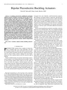
II. GUIDED WAVE RESONATORS In the design of acoustic wave resonator, the key point is to ensure a good isolation from substrate which leads to a better quality factor. For membrane type resonator (Lamb wave or FBAR), the isolation is obvious, since the resonator and its supporting membrane are suspended and are then naturally isolated from the substrate. For guided wave resonators, a Bragg mirror similar to the one used in SMR is needed. However, unlike the case of BAW resonators; the design of the Bragg mirror is more complicated for guided wave resonator, since 1D propagation perpendicular to the interfaces between layers can not be assumed. Indeed, the modes can be seen as a linear superposition of so-called partial waves (corresponding to the longitudinal and shear waves propagating in a homogeneous and unbounded medium). To improve structure isolation, these partial waves must be isolated from the substrate, taking into account the fact that one partial wave can be transmitted or reflected into another polarisation at the interface separating two layers (mode conversion). This mode conversion is illustrated in Figure 1. To be able to take mode conversions into account, the scattering matrix method is used for simulation [4].
I. INTRODUCTION Surface Acoustic Wave (SAW) and Bulk Acoustic Wave (BAW) are used in RF systems for their compactness and their high quality factors. To reach these high quality factors, the highest acoustic isolation must be achieved between the resonator and its support. In the case of SAW devices, isolation is naturally obtained through the guidance of waves by the surface. For BAW devices, two methods are commonly used: fabricating resonators on a membrane (Film Bulk Acoustic Resonator: FBAR) or above a Bragg mirror (Solidly Mounted Resonator: SMR). These two solutions enable trapping of vertically propagating waves in the piezoelectric layer. Waves propagating with lateral wave vectors can also be used to realize resonators. Lamb wave resonators fabricated on a piezoelectric membrane have been reported in the intermediate frequency range (~ 100 MHz) [1]. A lateral wave resonator can also exploit waves guided by a piezoelectric layer located above a Bragg mirror [2][3]. The use of a Bragg mirror to provide acoustic isolation is often preferred for RF applications because it is more compatible with industrial fabrication and improves other properties, like temperature compensation for example.
Longitudinal
Interface
In this paper, the design of resonators exploiting waves guided by a piezoelectric layer above a Bragg mirror is discussed. We will first describe the principle of this kind of devices and its operation. Then, we will deal with its design, with emphasis on the design of the Bragg mirror. Finally, we will show Finite Element/Boundary Element (FEM-BEM)
978-1-4244-1795-7/08/$25.00 ©2008 IEEE
Vertical Shear
581
Longitudinal
Vertical Shear
Al Mo W SiO2 Si
Interface
Figure 1. Partial waves in guided wave exhibits non-normal incident angle which leads to mode conversion occurs at interface between layers. Figure 3. Typical resonator stack. From bottom to top: the substrate, bragg layers (SiO2 and W), bottom electrode, piezoelectric layer and top electrode.
Guided waves have the main advantage of existing at any frequency [1]. Typical dispersion curves (plot of frequency vs wavelength) for a simple piezoelectric slab are plotted in Figure 2. When considering c-axis Aluminum Nitride (AlN), symmetric modes are mainly chosen because of their high coupling factor compared to asymmetric ones. We exploit the length-extensional (corresponding to the S0 Lamb waves for a simple slab, in blue in Figure 2) and the thicknessextensional (corresponding to the S1 Lamb wave, second red curve) modes shown in Figure 2. As we can see, the lengthextensional mode exists whatever the frequency. It is the natural choice in the design of intermediate frequency (about 400 MHz) resonators. At high frequency, the thicknessextensional mode is preferred for its high coupling factor and reasonable thickness requirements.
A. Bragg mirror design As explained earlier, the thickness-extensional mode is used for the range of frequency we are targeting. The Bragg mirror alone is considered, as shown in Figure 4.
Mo W SiO2 Si
x3 x1 Figure 4. Bragg mirror stack.
In the description of the guided waves, the partial longitudinal and shear waves cannot be considered separately. We need to take into account that part of the longitudinal (respectively shear) wave reflected into the other polarisation. Thus, it is convenient to rewrite the reflection coefficients as *
2
RL = RL + RL − SV
Figure 2. Typical dispersion curve for waves guided by a piezoelectric slab.
*
2
and
2
2
RSV = RSV + RSV − L . III.
RESONATOR DESIGN
(1)
For clarity, it is easier to replace these reflections by transmissions, defined as
A Typical resonator stack is shown in Figure 3. The substrate is considered as a semi-infinite layer. The Bragg mirror is made of tungsten (W) and silicon dioxide (SiO2). To be able to achieve the best acoustic isolation, thicknesses must be adjusted. Throughout this section, we will target a resonator operating at 1.96 GHz.
*
*
TL = 10 * Log (1 − RL ) and *
*
TSV = 10 * Log (1 − RSV ) .
(2)
These quantities are calculated as a function of the horizontal component of the wavevector and of frequency.
582
initial guess max(TL*,TSV*) is minimized using LevenbergMarquardt or Gauss-Newton algorithms. Transmission spectra obtained after this additional optimisation are plotted in Figure 6.
Therefore, the Bragg mirror is optimized for the targeted frequency as well as for a targeted wavevector. In a first step, all pairs of layers in the Bragg mirror are *
*
kept identical. Under this condition, TL and TSV are plotted in dB, versus the thickness of W, tW and of SiO2,
tSiO2 for a fixed value of the wavevector and of the frequency fc (Figure 5. T*
L
s1 = 0.1x10⁻⁴.
1.4
-5
-10
1.2
-15
1
t. SiO
2
-20
0.8
-25
-30
0.6 -35
0.4
-40
-45
0.2 0.2
0.4
0.6
0.8
1
1.2
1.4
t. W
(a) T*
SV
s1 = 0.1x10⁻⁴.
1.4
-5
-10
1.2
-15
1
t. SiO
2
-20
0.8
-25
Figure 6. Bragg mirror transmission spectrum.
-30
0.6 -35
0.4
-40
-45
0.2 0.2
0.4
0.6
0.8
1
1.2
The Bragg mirror obtained for a centre frequency
1.4
f c = 1.96 GHz, and a slowness s1 = 0.110−4 µm −1GHz −1 is
t. W
(b) Maximum of T* and T* L
SV
shown in Table I. s1 = 0.1x10⁻⁴.
1.4
TABLE I.
-5
-10
1.2
Layer number 6 5 4 3 2
-15
1
t. SiO
2
-20
0.8
-25
-30
0.6 -35
0.4
-40
-45
0.2 0.2
0.4
0.6
0.8
1
1.2
OPTIMIZED BRAGG MIRROR STACK THICKNESSES
Material SiO2 W SiO2 W SiO2
Thickness 0.10 µm 0.56 µm 0.53 µm 0.55 µm 0.50 µm
1.4
t. W
B. Dispersion curves analysis To validate the Bragg mirror design dispersion curves of guided waves are calculated. As shown in Figure 7, the dispersion curves exhibit a stop-band around the target frequency where a good isolation is achieved.
(c) Figure 5. Transmission curves in dB. (a)
TL
*
, (b)
TSV
*
(c)
max(TL*,TSV*).
In Figure 5. the green areas represent the highest reflection coefficients. In order to minimize layer thicknesses, we choose the first minimum, marked by the white rectangle in Figure 5. It is possible to further improve the Bragg mirror design by numerical optimisation. Considering previous result as
583
TABLE II.
2.5
Frequency (GHz)
2
Layer number 9 8 7 6 5 4 3 2 1
Stop-band
1.5
1
0.5
0 0
0.5
MATERIAL STACK FOR A 600 MHZ RESONATOR.
1
1.5
2
2.5
3
3.5
Material Mo AlN Mo SiO2 W SiO2 W SiO2 Si
Thickness 0.2 µm 2 µm 0.2 µm 1.4 µm 1.5 µm 2.0 µm 1.2 µm 1.0 µm Semi-infinite
The calculated electric response of such a resonator is plotted in Figure 9. Resonance occurs at 602 MHz, while a quality factor of 3500 is obtained when considering radiation within the substrate as the only loss source.
W avenumber k (µm-1) 1
Figure 7. Dispersion curves of guided waves in the optimized Bragg mirror and its associated stop-band.
The dispersion curves of the guided waves in the whole structure are plotted in Figure 8. The mode exploited for the resonator is marked by a white mark in Figure 8 and corresponds to the thickness-extensional mode. Dispersion curve of the whole stack 2.5
Frequency (GHz)
2
1.5
Figure 9. Impedance of a resonator using the length-extensional mode.
1
From the spacing of the resonance and antiresonance frequencies, we obtain an effective piezoelectric coupling factor of
0.5
0 0
0.5
1
1.5
2
2.5
3
3.5
4
W avenumber k (µm-1)
k2 =
1
Figure 8. Dispersion curves of guided waves in the AlN resonator over the optimized Bragg mirror.
2( Fa − Fr ) = 0.06 % Fa
This low value is attributed to the low piezoelectric coupling coefficient of the length-extensional mode in AlN. B. High Frequency resonator The FEM-BEM simulation results of the resonator operating in the high frequency range, is plotted in Figure 10. Its material stack is given in Table III.
IV. FEM-BEM SIMULATION The last step consists in a FEM-BEM analysis, using the combination of the Atila (FEM) and Microsonics (BEM) software [5]. The BEM part takes into account acoustic radiation into the semi-infinite substrate. Excitation electrodes are implemented as a set of interdigitated fingers whose period is half of a wavelength at operating frequency. A. Intermediate Frequency resonator The electrical response of a resonator designed for the low frequency range (600 MHz) and described in Table II is plotted in Figure 9. The corresponding material stack is given in Table II.
584
TABLE III.
MATERIAL STACK FOR A 1.6 GHZ RESONATOR
Layer number 9 8 7 6 5 4 3 2 1
Material Mo AlN Mo SiO2 W SiO2 W SiO2 Si
ACKNOWLEDGMENT
Thickness 0.2 µm 1.0 µm 0.2 µm 0.1 µm 0.6 µm 0.5 µm 0.6 µm 0.5 µm Semi-infinite
The authors thank Didace Ekeom for Microsonics software and his help. We are also grateful to Pascal Mosbah for his help when using the Atila software. Issiaka Koné work was supported by a STMicroelectronics-CNRS BDI grant. REFERENCES [1]
[2] [3] [4]
[5]
Figure 10. Impedance modulus.
A quality factor of 450 is obtained at a center frequency of 1.56 GHz. This low value is due to the spurious resonances located close to the main one, which broadens the resonance peak. From the spacing of the resonance and antiresonance frequency, an effective piezoelectric coupling factor of
k2 =
2( Fa − Fr ) = 2.19 % Fa
is obtained. As explained previously, high coupling factors of the thickness extensional mode allows to achieve large piezoelectric coupling factors. V. CONCLUSION The possibility of designing guided waves in a piezoelectric layer located atop a Bragg mirror has been theoretically studied. By analogy with lamb wave modes, both the length extensional mode in the low frequency range and the thickness extensional mode in the high frequency range have been exploited. It is shown that a Bragg mirror can be designed to confine waves in the guiding layer for all the modes studied. Further work will focus on the attenuation of spurious resonances caused by the fact that all modes are, to a certain extent, piezoelectrically coupled at non-zero wave vectors. This should increase quality factor and spectral purity.
585
A. Volatier et al., “UHF-VHF resonators using Lamb waves cointegrated with FBAR resonators”, Proc. IEEE Ultrason. Symp., 902-905, (2005). A. Khelif et al., Patent WO 2006/087496. R.F. Milsom et al., Patent WO 2006/126168 T. Pastureaud et al., “Stable scattering-matrix method for surface acoustic waves in piezoelectric multilayers”, Appl. Phys. Lett., vol 80, p 2544-2546, (2002). D. Ekeom et al., “Solidly Mounted resonator (SMR) FEM-BEM simulation”, Proc. IEEE Ultrason. Symp., 1474-1477, (2006).