fog computing frameworks and resource provisioning. Second, we describe .... colony, (iii) create a provisioning plan to allocate resources for task requests, and ...
2016 IEEE 9th International Conference on Service-Oriented Computing and Applications
Resource Provisioning for IoT Services in the Fog Olena Skarlat, Stefan Schulte, Michael Borkowski
Philipp Leitner
Distributed Systems Group, TU Wien Email: {o.skarlat, s.schulte, m.borkowski}@infosys.tuwien.ac.at
Department of Informatics, University of Zurich Email: leitner@ifi.uzh.ch
Abstract—The advent of the Internet of Things (IoT) leads to the pervasion of business and private spaces with ubiquitous, networked computing devices. These devices do not simply act as sensors, but feature computational, storage, and networking resources. These resources are close to the edge of the network, and it is a promising approach to exploit them in order to execute IoT services. This concept is known as fog computing. Despite existing theoretical foundations, the adoption of fog computing is still at its very beginning. Especially, there is a lack of approaches for the leasing and releasing of resources. To resolve this shortcoming, we present a conceptual framework for fog resource provisioning. We formalize an optimization problem which is able to take into account existing resources in fog/IoT landscapes. The goal of this optimization problem is to provide delay-sensitive utilization of available fog-based computational resources. We evaluate the resource provisioning model to show the benefits of our contributions. Our results show a decrease in delays of up to 39% compared to a baseline approach, yielding shorter round-trip times and makespans.
as a promising approach to reduce communication overhead and data transfer time in the IoT [5], [6]. To achieve this, it is necessary to move parts of the computational and storage resources needed to execute IoT services closer to the edge of the network [7]. The underlying conceptual approach, i.e., the virtualization of IoT devices and the subsequent usage of the virtualized resources to execute services, is known as fog or edge computing [4]. We use the term fog computing in the following. Fog computing mirrors the basic structure of the IoT, where a multitude of heterogeneous, networked devices cooperate [2], [7]. Fog cells, i.e., single IoT devices coordinating a group of other IoT devices and providing virtualized resources, are located close to the edge of the network. These cells allow executing IoT services close to the data sources or sinks, instead of involving the cloud. This leads to decreased delays, as well as a better utilization of already available computational, storage, and networking resources in the fog. Potential use cases for fog computing include typical IoT scenarios, e.g., data prefiltering in Big Data scenarios [8] or preprocessing of data streams from sensor nodes [9]. In many application areas, fog computing and cloud computing are combined in order to benefit from both computing paradigms. While the basic idea and theoretical foundations of fog computing are already established, there is still a lack of concrete solutions to implement fog computing in practice. Apart from the question of how to virtualize the resources offered by IoT devices, another major barrier for the uptake of fog computing is the question how to distribute IoT services on available fog resources. Therefore, in this paper, we introduce a conceptual framework for fog resource provisioning. For this, we apply the concept of fog colonies. Fog colonies are micro data centers made up from an arbitrary number of fog cells. As in a cloud data center, within a fog colony, task requests and data can be distributed and shared between the single cells. The operational purpose of fog colonies is the cooperative execution of arbitrary IoT services. Thus, fog colonies facilitate to move from centralized cloud-based data processing to a decentralized processing network that includes networked IoT devices, allowing cloud offloading and multi-cloud deployment. Based on this framework, we are able to orchestrate fog cells and to provide a suitable resource provisioning approach, i.e., a solution on how to distribute task requests and data among fog cells. For this, we formalize a system model which aims at minimization of delays arising from the transfer
I. I NTRODUCTION Due to the wide adoption of virtualization and cloud technologies, companies and end users nowadays have the means to lease and release computational assets in an ondemand, utility-like fashion [1]. As a second major technology trend, the arrival of the Internet of Things (IoT) leads to the pervasion of business and private spaces with ubiquitous computing devices, which are available in many forms, are able to act autonomously, and are connected to both the Internet and other devices [2]. Furthermore, IoT devices, e.g., IoT gateways, sensor nodes, or single board computers used in IoT environments, do not simply act as sensors, but feature computational, storage, and networking resources. Together, the proliferation of cloud and IoT technologies enables both, small-scale and large-scale smart environments and systems for various domains, such as smart healthcare, smart cities, smart energy grids, or smart factories [3]. However, from a technical point of view, the decentralized nature of the IoT does not match the rather centralized structure of the cloud. Today, IoT data is often sourced in a distributed way, sent to a centralized cloud for processing, and is then delivered to the distributed stakeholders interested in this data or other IoT (edge) devices, which in many cases are located close to the data sources. This results in high link delays and, accordingly, low data transfer speed between IoT devices as well as the IoT devices and potential users [4]. In order to prevent this, the support of decentralized processing of data on IoT devices in combination with the benefits of cloud technologies and virtualization has been identified 978-1-5090-4781-9/16 $31.00 © 2016 IEEE DOI 10.1109/SOCA.2016.10
32
times between the fog and the cloud, and at maximization of resource utilization of existing fog cells. For evaluating the proposed system model, we apply different scenarios and resource provisioning policies. The goal of the evaluation is to identify the best provisioning policy by comparing suitable metrics, i.e., round-trip time, delay, makespan, and cost. The remainder of this paper is organized as follows: In Section II we discuss the state-of-the-art work in the area of the fog computing frameworks and resource provisioning. Second, we describe the architecture of our conceptual fog computing framework in Section III. Next, in Section IV, we formalize the envisioned resource provisioning model. We evaluate the model extensively in Section V. Finally, we conclude the paper in Section VI.
a more sophisticated resource provisioning mechanism, which is based on the prediction of resource demands [12], [13]. The dynamic allocation of resources is performed in advance during the design time of the system. This approach is based on cost optimization, and resource allocation depends on the probability fluctuations of the demand of the users, types of services, and pricing models. Cost function parameters are set up during the time the contract between the user and provider is negotiated. The approach also takes user incentives and encouragement mechanisms into account. In contrast, our work provides runtime resource provisioning, i.e., accounts for dynamic infrastructural changes in a fog colony. Apart from fog-specific resource provisioning solutions, resource allocation and service scheduling are major research challenges in the general field of cloud computing [14], [15], [16]. While these approaches offer interesting insights, there are certain differences between fog services and cloud services. These prevent a direct adaptation for the use in the work at hand. First, the size and type of cloud resources is very different from its counterparts in fog computing. While cloud resources are usually handled on the level of physical machines, virtual machines (VMs), or containers, fog resources are usually not as powerful and extensive. Second, fog colonies may be distributed in a rather large area and heterogeneous network topology, while cloud resources are usually placed in centralized data centers, making it more important to take into account data transfer times and cost in the fog. This is especially important since one particular reason to use fog computing in IoT scenarios is the higher delay-sensitivity of fog-based computation [4]. Hence, resource provisioning approaches for the fog need to make sure that this benefit is not foiled by extensive data transfer times and cost. Resource allocation and service scheduling is also an important topic in mobile cloud computing (MCC) [17], which integrates mobile devices (most importantly smartphones) and cloud resources and offers solutions for offloading tasks from mobile devices to the cloud [18]. However, MCC is mostly based on a rather simple network topology with direct communication between mobile devices and the cloud. Neither groups of devices (as in fog colonies), nor the different layers observed in fog computing are taken into account in MCC. Therefore, again, the according resource provisioning approaches offer interesting insights and ideas, but cannot be directly ported to the field of fog computing.
II. R ELATED W ORK As fog computing is still a very recent research topic, there is a lack of concrete solutions supporting this computing paradigm. Nevertheless, there is some conceptual as well as fundamental work in related areas, which needs to be regarded. First, there has been some work on fog computing architectures. In their seminal conceptual work on the topic, Bonomi et al. introduce a layered model bridging the IoT and the cloud [5]. The authors show that applications might be placed in the cloud and in the fog, spanning potentially different cloud providers. In addition, it is shown that a fog computing framework needs to allow the communication between the cloud and the fog, inside the fog, and between the fog and IoT devices. Dastjerdi et al. [7] present a reference architecture for fog computing which follows a very similar structure if compared to the work by Bonomi et al. The reference architecture implies serving IoT requests in the local fog rather then involving the cloud. In the reference architecture, central fog services are placed in a SoftwareDefined Resource Management layer, which provides a cloudbased middleware. Notably, this prevents that fog colonies act in an autonomous way. Instead, fog cells are analyzed, orchestrated, and monitored by the cloud-based middleware. Also, fog resource provisioning and the offloading of computational tasks from the fog to the cloud are achieved through the middleware. In another discussion of basic fog features, Vaquero et al. [10] considers different concepts to realize fog architectures, including both centralized and decentralized, i.e., peer-to-peer, approaches. Notably, the authors introduce the notion of edge clouds, which are private fogs made up from IoT devices, resembling our notion of fog colonies. The conceptual frameworks discussed so far do not take into account the concrete needs of fog resource provisioning. Instead, the focus is on the communication and task sharing between the different layers, i.e., cloud, fog, and IoT. In fact, the number of resource provisioning mechanisms specifically aiming at fog computing is quite limited so far: Hong et al. present a programming model including a simple resource provisioning strategy, which relies on workload thresholds, i.e., if the utilization of a particular fog cell exceeds a predefined value, another fog cell is leased [11]. Aazam and Huh present
III. F OG C OMPUTING F RAMEWORK In this section, we present the architecture of our fog computing framework as depicted in Figure 1. The framework enables the enactment of IoT services in an arbitrary fog landscape. This allows to optimize resource provisioning in the fog, as discussed in Section IV. Following the basic structure of fog computing as presented in [5], [7], we allow for resource provisioning and orchestration in both the cloud and fog. To achieve this, a cloud-fog control middleware (see Section III-A) is introduced, which controls fog cells (see Section III-B). As discussed
33
fog colony
compute units
cloud clo
storage s torage e
Deploy API
Data API fog cell
cloud–fog control middleware
fog orchestration control node
shared storage
fog colony
watchdog
database service registry
reasoner R
fog cell
fog cell
IoT device
IoT device
IoT device
IoT device
fog cell
ffog fo g cell
IoT device
IoT device
R
compute unit
R R
fog colony fog orchestration control node
propagation component
computational components storage components
R
IoT
R
fog colony fog orchestration control node
monitor
listener
Deploy API
fog action control
networking components fog orchestration control node extensions consumed interfaces exposed interfaces
Data API
Fig. 2. Fog Cell and Fog Orchestration Control Node Architecture
IoT device
control nodes in fog colonies, but the latter may also act autonomously in the case that no middleware is available.
Fig. 1. Fog Computing Framework Overview
above, fog applications should also be executable without any involvement of the cloud. Hence, another level of control is necessary, which needs to run exclusively in the fog. For this, we introduce fog orchestration control nodes, which are a specific kind of fog cells (see Section III-C). A fog orchestration control node manages a number of fog cells or other control nodes connected to it. As it was already mentioned in Section I, we call such structures fog colonies. In our framework, we support a hierarchy of fog colonies with a head element in the cloud, i.e., the cloud-fog control middleware. The further layers of the hierarchy are the fog orchestration control nodes, the fog cells, and finally the IoT devices at the very bottom of the hierarchy (see Figure 1). In the following, we use the notion of task requests for computational duties which need to be accomplished using cloud or fog resources. The actual software instances executing these task requests are called services. Possible examples of such services include stream processing, MapReduce applications, or distributed data storage.
B. Fog Cells Fog cells are software components running on fog devices. Fog cells serve as access points allowing the control and monitoring of the underlying IoT devices, e.g., sensor nodes. In order to do so, the fog cells are able to receive task requests, perform data analysis, allocate their own computational resources if available, or propagate task requests to upper layers of the fog colony hierarchy, i.e., to the fog orchestration control nodes (as discussed below). Cells may interact with an arbitrary number of IoT devices, however, in practice, the number of devices to be controlled by a fog cell is limited by the cell’s computational resources. Each fog cell consists of the following components (Figure 2): The listener receives task requests from other fog cells or IoT devices. The monitor observes service executions in the compute unit. The database stores data about received task requests, the current system state of the fog cell, i.e., available computational and storage resources, and monitoring data. The fog action control performs actions according to the provisioning plan produced by the fog orchestration control node, e.g., to deploy and start a particular service (see Section III-C). Fog cells access the distributed storage to share data, e.g., service implementations, in a colony. This component allows faster data access compared to data storage in the cloud. The compute unit provides the actual computational resources for the deployment and execution of services. Fog cells expose REST APIs for data transfer and control actions: The Data API allows basic CRUD operations over the data stored within a fog cell, and the Deploy API allows performing control actions for the services running in the fog cell, i.e., instantiating, deploying, starting, stopping, undeploying, and deleting the service. To become part of a fog colony, a fog cell needs to use the Data and Deploy APIs of the corresponding fog orchestration control node, and at the same time expose its own Data API and Deploy API.
A. Cloud-Fog Control Middleware The cloud-fog control middleware is the central unit that manages the execution of task requests in the cloud, and supports the underlying fog landscape. The middleware performs cloud resource provisioning for task requests that are not delay-sensitive or cannot be executed in the fog, e.g., very resource-intensive Big Data analysis task requests. If necessary, the middleware performs global optimization of underlying fog colonies by restructuring them. For this, the cloud-fog control middleware is supplemented by both the means to control the cloud and the means to manage the underlying fog colonies. Such control is performed continuously or on-demand, depending on system events, e.g., if new fog devices appear, which could be used to deploy fog cells, or to recover after faults or damage of fog cells. Importantly, the cloud-fog control middleware can overrule fog orchestration
34
C. Fog Orchestration Control Nodes
extensive coordination and voting between the involved fog cells. Therefore, we opt for a more centralized approach in this work. However, we still foresee that another fog cell becomes the fog orchestration control node in a fog colony, if necessary, e.g., in case the original fog orchestration control node fails.
A fog orchestration control node’s main task is to support a fog colony by orchestrating the involved fog cells. Each fog colony features exactly one head fog orchestration control node. The fog orchestration control node is itself a (powerful) fog cell, which manages the resources offered by subordinated fog cells and performs resource provisioning to execute task requests. Also, the control node is able to propagate task requests to the cloud-fog control middleware or to other fog colonies (via their fog orchestration control nodes), if task requests cannot be handled by the current fog colony. For this, a resource management mechanism for vertical scalability is necessary to identify how task requests can be delegated in the entire fog landscape. Apart from resource provisioning, fog orchestration control nodes (i) perform infrastructural changes in the fog colony, (ii) analyze resource utilization within the colony, (iii) create a provisioning plan to allocate resources for task requests, and (iv) monitor IoT devices and fog cells. An approach to optimize task request distribution and resource allocation is described in Section IV. As previously mentioned, fog orchestration control nodes are extended fog cells. On the left-hand side of Figure 2, the extensions needed for control nodes are depicted. The reasoner component produces a provisioning plan for the colony’s resources to execute received task requests. The provisioning plan determines which services should be used to fulfill task requests, and where these services should be deployed, i.e., what fog cell to use. The reasoner also gets the information about the system state, i.e., available fog colony resources, and controls the connected fog cells, i.e., plans infrastructural changes in the fog colony, if necessary. The database additionally stores the resource provisioning plan produced by the reasoner. After the reasoner produces a provisioning plan, the fog action control performs the orchestration of fog cells according to the plan. If there are no sufficient resources in the considered fog cell, or further processing is needed, such task requests are separated and propagated to the other fog colonies by the propagation component via the control node. The watchdog component features means to receive up-to-date information about the utilization of the connected fog cells. It observes monitoring data in the database and compares it to the expected Quality of Service (QoS) level, i.e., measures the consumption of the cell’s computational resources as well as QoS parameters, e.g., the execution time. This information influences the decisionmaking in the reasoner component. The service registry component hosts service implementations and enables the fog action control to search for services and deploy them on the fog cell compute units. As storing service implementations is resource-consuming, the service registry is located in the storage unit of the control node. It should be noted that an alternative approach would be a decentralized orchestration of fog cells in a fog colony, i.e., without a centralized fog orchestration control node. While this leads to higher fault tolerance, it also involves
IV. F OG R ESOURCE P ROVISIONING As discussed in Section III, it is necessary to provide the fog orchestration control node (more precisely: the reasoner component) as well as the cloud-fog control middleware with means to allocate resources for task requests. For this, the fog orchestration control node needs a complete overview of the system state of a fog colony. With this system state as input, the reasoner is able to compute a resource provisioning plan and to schedule task requests onto services running in fog cells. As stated above, we assume that a fog colony is autonomous, i.e., the cloud-fog control middleware is only involved if a fog colony needs additional cloud resources. As in the field of cloud resource optimization, manifold goals for resource provisioning are possible, e.g., time, cost, or energy efficiency optimization [6], [10], [12]. In the following, the goal of our resource provisioning approach is the optimization with regard to the utilization of the fog cells and minimization of delays. First, this means that the computational resources offered by the fog cells should be utilized as much as possible, because using cloud resources instead leads to higher overall cost (for details, see Section V-C). Second, the data needed and sourced within a particular fog colony should be handled by that particular colony, if possible. This is done in order to avoid an increase of delays by propagating data to the cloud. Together, these goals form the foundation for a multiple-criteria optimization problem, as will be presented in the upcoming subsections. Based on the solutions to this optimization problem, a fog orchestration control node instantiates services on particular fog cells and schedules task requests on these cells. A. System Model The basic entity for optimization in our system model is a fog colony with a fog orchestration control node F . F has n subordinate children fog cells f j , i.e., fog cells are part of the same fog colony and controlled by F : ∀f j ∈ F C , j ∈ {1..n}. The CPU utilization of a control node is indicated by U F , for a children fog cell by U j . Analogously, for RAM utilization, the parameters M F and M j are used. There are different types of fog cells (T F for control nodes, T j for children fog cells), which indicate the sets of services that can be run on this particular cell, i.e., indicate different IoT devices. The bandwidth and link delay between a control node and a particular children fog cell j are indicated by bj and dj . The fog colony controlled by F receives m task requests. Each request ri , ∀ri ∈ R, i ∈ {1..m} is characterized by two time points: ts and tf , where ts is the time when a task request enters the system and tf is the time when the task request is and RAM fulfilled. Each ri is characterized by its CPU μCPU i
35
μRAM demand, and the type of service μTYP needed to fulfill i i the task request. The current system state is indicated by the period τ and its starting point of time tτ . The fog cell produces the resource provisioning plan S for the period τ + 1 with a starting point of time tτ +1 calculated by adding a certain period of time �: tτ +1 = tτ + �. We define the cardinality function, i.e., length, of the whole resource provisioning plan S which consists of a sequence of assignments for children fog cells S(F C ), for the control node S(F ), and for not assigned � task� requests S(0), for all i ∈ {1..m}, i.e., S = S(F C ) S(F ) S(0). j requests rkj , We assume for � cell f the assigned task � a fog j j j F ∀rk � ∈ R , k� ∈ 1..p , for the control node rq , ∀rqF ∈ RF , q ∈ 1..uF . If for some task requests there are no resources in the fog colony, or the task request needs further resources which cannot be offered by the colony itself, the resource provisioning plan S is still produced, but not assigned task � �n �pj j � �uF F requests R \ j=1 k=1 (rk ) \ q=1 (rq ) are propagated to a higher layer in the fog colony. This higher layer could either be another fog orchestration control node (in the case of nested fog colonies) or the cloud-fog control middleware. The objective of (1), our overall goal function, is to maximize the number of possible assignments while decreasing the propagation of task requests to the higher layer as much as possible. � |S(F C ) S(F )| → max (1)
As defined in (5) and (6), assigned task requests must not exceed the resources of a fog cell. The equations allow for an assumed percentage γ of system needs that must be free to maintain a corresponding fog cell. m
m i=1
γ ) , ∀j ∈ {1..n} 100
(6)
A. Evaluation Environment In order to cope with fog landscapes, CloudSim needs to handle fog colony hierarchies as introduced in Section III. For this, the original Datacenter class of CloudSim is extended by FogDatacenter that features specific methods of a fog colony, i.e., linking different fog cells to a fog orchestration control node. CloudSim’s DatacenterBroker class is extended by FogBroker that mirrors the behavior of the fog orchestration control nodes or cloud-fog control middleware depending on the simulated environment, and implements the system model presented in Section IV. CloudSim’s class responsible for task requests, Cloudlet, is extended by FogCloudlet to include the issuer parameter. This is necessary to track the origin of task requests. To calculate delays (see Section V-C), a class DelayEntity is added. This class transforms data from CloudSim’s class NetworkTopology, and is used for metric calculations. The main class of the simulation creates the fog landscape and cloud environment, sets up the services, generates task requests in the fog cells, and finally runs the simulation. B. Experimental Setup
As a first constraint, we assume that each fog cell of a specific type T j can execute certain types of task requests, i.e., the type of a task request must be checked. If the task request is assigned to a fog cell, meaning xji = 1, then the type of a task request must conform to the type of the fog cell, i.e., μTYP ∈ T j . And, correspondingly, if the task request i TYP is assigned to the control node, i.e., xF ∈ TF. i = 1, then μi Second, each task request ri can be assigned only to one specific fog cell f j or F :
j=1
(μRAM · xji ) ≤ M j · (1 − i
In the following evaluation, we show the efficiency of our resource provisioning approach, compared to a baseline approach and to the execution in the cloud. For this, we extend the well-known CloudSim modeling and simulation framework [19] with the means to simulate fog landscapes.
j=1
(xji ) + xF i ≤ 1 ,∀i ∈ {1..m}
(5)
V. E VALUATION
Based on this, the goal function can be rewritten as (3). m n � → max (3) (xji ) + xF i
n
γ ) , ∀j ∈ {1..n} 100
i=1
The binary variable xji decides whether a task request ri is assigned to f j as defined in (2). For control nodes, xF i is defined analogously. � 1, if ri is assigned tof j , j xi = (2) 0, if ri is not assigned tof j ,
i=1
(μCPU · xji ) ≤ U j · (1 − i
As a fog landscape, we consider a fog colony of 100 fog cells (each running on a separate IoT device) and a fog orchestration control node. The fog colony is linked to a public cloud in the case that cloud resources are necessary for the fulfillment of task requests. Of these 100 fog cells, 10 are simultaneously issuing 1,000 task requests to the fog colony (more precisely: to the control node) assuming these fog cells do not have enough own resources for processing. This leaves 90 fog cells to provide computational resources to handle the 1,000 task requests. If these fog cells are not sufficient, cloud-based computational resources are used to fulfill the task requests. Each fog cell executes different services according to the available computational power. For the simulation, we do not restrict the service types to be hosted by the single fog cells, i.e., each cell is able to respond to every task request. CloudSim calculates the execution time of a service needed to fulfill a particular task request by taking into account the
(4)
Next, we choose a fog cell with minimum estimated delay between the fog cell and the control node. For that, the set of all fog cells is sorted according to the value dj . This allows the assignment of task requests prioritizing fog cells with lesser delay.
36
core (mips)
1000
rn ... rm+1 rm ... rl+1 rl ... rk+1 rk ... r1
750 500 250
core (mips)
rm+1
...
rn
rl+1
...
rm
rk+1
...
rl
r1
...
rk
250
time
(1-a) 1000
750
Service 1 Service 2 Service 3 Service 4
500
time
(1-b)
core (mips)
core (mips)
1000
1000
rk
rn
rm
rl
750
750
...
r1
rk+1
rl+1
rm+1
...
...
250
250
time
(2-a)
...
...
rn
...
rm+1 rm
...
rl+1 rl
...
rk+1 rk
500
500
r1
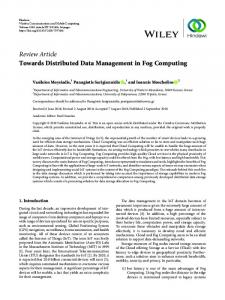
number of instructions necessary to execute the task request and the number of instructions a compute unit is able to process per second. Within our evaluation, a task request needs 0.04 million of instructions per second (mips), and has 300 MB of incoming and 300 MB of outgoing data. Fog cells possess compute units which are able to handle 250 mips. For modeling the fog network capacities, i.e., the network topology, the BRITE internet topology generator [20] is used. The one-way delays between fog cells and the control node were generated by BRITE according to the physical distance between generated nodes, and belong to the interval (0, 1] seconds. The cloud-based computational resources are set to be twice as powerful as fog cells’ compute units, i.e., VMs are able to handle 500 mips. The cost per processing in the cloud is set to $ 0.30 per Billing Time Unit (BTU), i.e., one hour. The delay between the control node and the cloud was set to 2 seconds. The bandwidth between the control node and fog cells is set to 6 Mbit/s, and between the cloud-fog control middleware and the control node to 10 Mbit/s. For evaluating the efficiency of the fog landscape, we apply the resource provisioning policies offered by CloudSim [19] (called the “Baseline” scenario) and our system model (introduced in Section IV) combined with those policies (called the “Optimization” scenario) in the fog landscape. Furthermore, we perform an execution of all task requests in the cloudfog control middleware for the case the fog landscape is not available (called the “Cloud” scenario). Basically, CloudSim allows time-shared and space-shared provisioning policies for both computational resources and services running on those resources. Time-shared provisioning means that the shared resource is simultaneously divided among assigned entities, i.e., the entities run in parallel. The space-shared provisioning means that the computational power of the resource is shared, and the resource is provisioned to an entity sequentially, i.e., the next entity starts running only when the previous entity is finished. Applied to fog computing as discussed in this paper, we distinguish four basic policies, as depicted in Figure 3: (1-a) time-shared provisioning of fog cells for services and time-shared provisioning inside services for task requests; (1-b) time-shared provisioning of fog cells for services and space-shared provisioning inside services for task requests; (2-a) space-shared provisioning of fog cells for services and time-shared provisioning inside services for task requests; (2-b) space-shared provisioning of fog cells for services and space-shared provisioning inside services for task requests.
time
(2-b)
Fig. 3. Provisioning Policies
The round-trip time ti is the time a task request spends in the fog landscape from the moment of issuing until getting back the results of the processing. In Table I, we show the average round-trip time per task request along with the standard deviation of the results. The round-trip time of each task request is calculated as the sum of the duration of uploading data to the control node’s host and to the destination fog cell’s host for execution along with according delays, the execution time, and downloading data back to the issuer of the task request: {srcri ,F }
ti = tup
{F,destri }
+ d{srcri ,F } + tup
{destri ,F }
+ tiexec + tdown
+ d{F,destri } +
{F,srcri }
+ d{destri ,F } + tdown
+ d{F,srcri }
(7)
Uploading and downloading times are calculated according to CloudSim’s basic methods, i.e., dividing an incoming and outgoing storage capacities of task requests by a corresponding bandwidth of the used network link: sizerupi sizeri {start, end} end} = {start, end} ; tdown = {start,down (8) t{start, up end} b b We assume that the execution time includes the actual task request execution time in a service, and processing times needed by the control node and the destination fog cell. Taking into account the number of assigned task requests from (3), the delay d{srcri ,F } between the issuer of the task request and F , the delay dj between F and each fog cell, and the delay dC between F and the cloud, we calculate the total delay in the fog: m m n delayfog = 2 · d{srcri ,F } + 2 · (xji · dj )+
C. Metrics
+2· m−
To assess the efficiency of the fog landscape in the Baseline, Optimization, and Cloud scenarios, we calculate the average round-trip time per each task request (7)–(8), total delays for the execution of all task requests (9)–(10), and the total makespan, i.e., the time period between the entering of the first task request into the fog landscape and the fulfillment of all task requests. Additionally, for the execution in the cloud we calculate the total cost (11).
i=1
m n i=1
j=1
i=1 j=1
(xji )
+
xF i
��
·d
(9)
C
In the case of execution of task requests in the cloud, the delay to the destination equals to dC for all m task requests, and the total delay equals to: m delaycloud = 2 · d{srcri ,F } + 2 · m · dC (10) i=1
37
2075
360.8
2055 2035
360.6
2015
360.4
1.0
Delay (s)
361.0
2095
Round-trip time (s)
Round-trip time (s)
1.2
361.2
2115
0.8
0.6 0.4
1995 1975 1955 0
100
200
300
Left vertical axis: Right vertical axis:
400
500
600
Task request id (1-a) (1-b)
700
800
360.2
0.2
360.0
0.0
900
0
100
200
300
400 500 600 700 Task request id Baseline Optimization
(2-a) (2-b)
Fig. 4. Round-trip Times for Task Requests in the Optimized Fog Landscape
800
900
Fig. 5. Baseline and Optimization scenarios for the Provisioning Policies 1-a and 1-b
In our experimental setup, the task requests are issued simultaneously, but have different start times of execution according to the policy applied. The total makespan is calculated as the maximum value of an array of summed values of start time of the execution with the round-trip time of the corresponding task request. We assume ownership of the fog and that these resources are available anyway, as discussed in Section I. Therefore, the fog cost can be neglected. The cost is calculated for the cloud execution according to (11), where ccloud is the cost per processing second in the cloud and v is the amount of seconds in 1 BTU: m i t · ccloud costcloud = i=1 exec (11) v D. Results
1.2
Delay (s)
1.0
0.8 0.6 0.4 0.2 0.0
0
100
200
300
400 500 600 700 Task request id Baseline Optimization
800
900
Fig. 6. Baseline and Optimization scenarios for the Provisioning Policies 2-a and 2-b
relatively small, because all the task requests are executed sequentially in the services, and release resources immediately after the execution. Therefore, the round-trip time is affected more by the corresponding delays. In contrast, policies 1-a and 2-a execute task requests in parallel, which make the execution slower. The system model applied to the policies 2-a and 2-b brings improvements, however they are marginal. The total makespan periods of all fog landscape scenarios are relatively the same, however policy 1-b shows better results as well because of reduced delays. The cloud scenario shows smaller round-trip time and total makespan because of higher bandwidth, i.e., the data is uploaded quicker, compared to the fog landscape where the data is transferred between fog cells. However, the delay between the control node and cloud-fog control middleware was set to a relatively small value of two seconds (see Section V-B), and anyway the execution in the cloud shows around 95% higher delay compared to the Optimization scenario in the fog. In reality the link delay between the control node and the cloud depends on the physical distance to the cloud. Additionally, the cloud scenario has cost for the execution. These results compensate the benefit from the smaller round-trip time and makespan. In total, the evaluation demonstrates that the system model applied with the time-shared provisioning of fog cells for services along with space-shared provisioning inside services for task requests, i.e., Optimization scenario for (1-b), reduces delays in the fog landscape by 39%. It also shows less average round-trip time per each task request compared to the other policies. Lesser round-trip time is crucial if there are any
Even though the provisioning inside a service for task requests has no influence on the delay minimization between fog cells (see Figure 3), it still influences the start and finish times of task request executions, and consequently affects the round-trip time per task request. The purpose of Figure 4 is to demonstrate visually which policy shows better round-trip times according to the Optimization scenario. According to Figure 4, the policy 1-b shows the least round-trip times for each task request in the simulated fog landscape, which is also supported by the results shown in Table I. The default CloudSim time-shared VMs provisioning policy assigns VMs to data centers in the sequence these data centers are described in the network topology. According to the system model (see Section IV), we compare the hosts of fog cells according to their link delays to the control node, and prioritize fog cells with lesser delays. The conducted simulations confirm that the resource provisioning inside a service has no influence on the delays. Figure 5 shows the change in delays for policies 1-a and 1-b, and Figure 6 respectively for 2-a and 2-b. In the figures, the delays drop down because already allocated fog cells become free after fulfilling the assigned task requests, and afterwards other task requests are assigned to those fog cells due to the lesser link delay constraint. As seen in Table I, policies 1-a and 1-b decrease the total delay in the optimized fog landscape by 39% compared to the Baseline, and policy 1-b has also 82% less average round-trip time compared to 1-a. The standard deviation for the average round-trip time for the policies 1-b and 2-b is
38
TABLE I M ETRICS C OMPARISON Policy (1-a) (1-b) (2-a) (2-b)
Average round-trip time (s) Baseline Optimization Cloud 1979.69 1979.48 1056.04 σ=44.49 σ=51.97 σ=25.96 360.53 360.32 246,46 σ=0.20 σ=0.14 σ=1.35 1979.65 1979.65 1056.04 σ=51.99 σ=51.92 σ=25.96 360.50 360.49 246.46 σ=0.19 σ=0.20 σ=1.35
Baseline
Total delay (s) Optimization
Cloud
Baseline
530.82
323.68
6454.50
2123.07
2122.82
1129.05
74.13
530.96
323.90
6455.00
2122.61
2122.54
1126.22
6.67
492.78
490.63
6454.50
2129.96
2129.54
1129.05
74.13
493.03
490.91
6455,00
2129.71
2129.28
1126.22
6.67
time constraints for task requests executions, and especially in delay-sensitive fog scenarios, as discussed before.
Total makespan (s) Optimization Cloud
Cost ($) Cloud
[4] F. Bonomi, R. Milito, J. Zhu, and S. Addepalli, “Fog computing and its role in the internet of things,” in MCC Workshop on Mobile Cloud Computing, 2012, pp. 13–16. [5] F. Bonomi, R. Milito, P. Natarajan, and J. Zhu, “Fog Computing: A Platform for Internet of Things and Analytics,” in Big Data and Internet of Things: A Roadmap for Smart Environments, ser. Studies in Computational Intelligence, 2014, vol. 546, pp. 169–186. [6] A. Papageorgiou, B. Cheng, and E. Kovacs, “Real-Time Data Reduction at the Network Edge of Internet-of-Things Systems,” in 11th Intern. Conf. on Network and Service Management, 2015, pp. 284–291. [7] A. V. Dastjerdi, H. Gupta, R. N. Calheiros, S. K. Ghosh, and R. Buyya, “Fog Computing: Principles, Architectures, and Applications,” in Internet of Things: Principles and Paradigms, 2016, ch. 4. [8] M. Chen, S. Mao, and Y. Liu, “Big Data: A Survey,” Mobile Networking and Applications, vol. 19, no. 2, pp. 171–209, 2014. [9] C. Hochreiner, M. V¨ogler, P. Waibel, and S. Dustdar, “VISP: An Ecosystem for Elastic Data Stream Processing for the Internet of Things (forthcoming),” in 20th IEEE Enterprise Distributed Object Conf., 2016. [10] L. M. Vaquero and L. Rodero-Merino, “Finding your Way in the Fog: Towards a Comprehensive Definition of Fog Computing,” ACM SIGCOMM Computer Communication Review, vol. 44, no. 5, pp. 27– 32, 2014. [11] K. Hong, D. Lillethun, U. Ramachandran, B. Ottenwlder, and B. Koldehofe, “Mobile Fog: A Programming Model for LargeScale Applications on the Internet of Things,” in 1st ACM SIGCOMM Workshop on Mobile Cloud Computing, 2013, pp. 15–20. [12] M. Aazam and E. N. Huh, “Dynamic Resource Provisioning Through Fog Micro Datacenter,” in 12th IEEE Intern. Workshop on Managing Ubiquitous Communications and Services, 2015, pp. 105–110. [13] ——, “Fog Computing Micro Datacenter Based Dynamic Resource Estimation and Pricing Model for IoT,” in 29th IEEE Intern. Conf. on Advanced Information Networking and Applications, 2015, pp. 687–694. [14] Z.-H. Zhan, X.-F. Liu, Y.-J. Gong, J. Zhang, H. S.-H. Chung, and Y. Li, “Cloud Computing Resource Scheduling and a Survey of Its Evolutionary Approaches,” ACM Computing Surveys, vol. 47, no. 4, 2015. [15] S. Singh and I. Chana, “QoS-Aware Autonomic Resource Management in Cloud Computing: A Systematic Review,” ACM Computing Surveys, vol. 48, no. 3, 2016. [16] P. Leitner, W. Hummer, B. Satzger, C. Inzinger, and S. Dustdar, “Costefficient and application sla-aware client side request scheduling in an infrastructure-as-a-service cloud,” in 5th Intern. Conf. on Cloud Computing, 2012, pp. 213–220. [17] N. Fernando, S. W. Loke, and W. Rahayu, “Mobile cloud computing: A survey,” Future Generations Computer Systems, vol. 29, pp. 84–106, 2013. [18] H. T. Dinh, C. Lee, D. Niyato, and P. Wang, “A Survey of Mobile Cloud Computing: Architecture, Applications, and Approaches,” Wireless Communications and Mobile Computing, vol. 13, pp. 1587–1611, 2013. [19] R. N. Calheiros, R. Ranjan, A. Beloglazov, C. A. De Rose, and R. Buyya, “CloudSim: a toolkit for modeling and simulation of cloud computing environments and evaluation of resource provisioning algorithms,” Software – Practice and Experience, vol. 41, pp. 23–50, 2011. [20] A. Medina, A. Lakhina, I. Matta, and J. Byers, “BRITE: An Approach to Universal Topology Generation,” in Intern. Workshop on Modeling, Analysis and Simulation of Computer and Telecommunications Systems, 2001, pp. 346–354.
VI. C ONCLUSIONS The centralized processing of multiplicative IoT data in the cloud incurs high delays and accordingly low speed of data processing which are unfavorable for IoT applications and services. Fog computing promises to solve this problem by utilizing available computational, storage, and networking resources for the enactment of IoT services close to the edge of the network. Currently, the uptake of fog computing is still at its very beginning, thus there is a lack of theoretical and practical foundations for fog resource provisioning. After having motivated our work, we discussed an architecture for fog computing framework, and derived a system model for fog resource provisioning. To evaluate the efficiency of the proposed approach, we simulated the envisioned architecture. We showed that the system model combined with the timeshared provisioning of fog cells for services along with spaceshared provisioning inside services for task requests decreased delays by 39% and yielded shorter round-trip times and makespans. In our future work, we aim to implement a real-world testbed based on the proposed architecture and to improve the system model for resource provisioning. The architecture can be enhanced by fault tolerance mechanisms, and by adding QoS constraints to the task requests, e.g., deadlines. Another aspect of our future work is the systematic evaluation of a fog landscape to obtain real-world network data for evaluations, e.g., delays and bandwidth. ACKNOWLEDGMENT This paper is supported by TU Wien research funds. This work is partially supported by the Commission of the European Union within the CREMA H2020-RIA project (Grant agreement no. 637066). R EFERENCES [1] M. Armbrust, A. Fox, R. Griffith, A. D. Joseph, R. Katz, A. Konwinski, G. Lee, D. Patterson, A. Rabkin, I. Stoica, and M. Zaharia, “A View of Cloud Computing,” Comm. of the ACM, vol. 53, pp. 50–58, 2010. [2] L. Atzori, A. Iera, and G. Morabito, “The Internet of Things: A survey,” Computer Networks, vol. 54, pp. 2787–2805, 2010. [3] A. Botta, W. de Donato, V. Persico, and A. Pescape, “Integration of cloud computing and internet of things: a survey,” Future Generation Computer Systems, vol. 56, pp. 684–700, May 2016.
39