Reuse and Validation of Requirements for Mobile Systems Rossana Andrade, Luigi Logrippo Universidade Federal do Ceará, Departamento de Computação, Campus do Pici, Bloco 910 Fortaleza, Ceará, Brasil
[email protected] School of Information Technology and Engineering, University of Ottawa, 150 Louis Pasteur, MCD 310-B, Ottawa, Ontario, K1N 6N5, Canada
[email protected] ABSTRACT In the mobile wireless communication domain, different systems apply common solutions to similar functional and architectural design problems. The recognition of these commonalities is a starting point towards ironing out differences and possibly towards finding better ways to interwork different systems and to develop new ones. There is therefore a need for recognizing and reusing these commonalities. The concept of pattern, which is used in the software community to describe programming solutions to specific recurring problems, can be adopted for this purpose. This paper proposes an approach for reuse and validation of a set of solutions for mobility and radio resource management functions, solutions that have been identified as common among a number of second and third generation systems. The focus is on the early development stages. A visual technique called Use Case Maps (UCMs) is applied to graphically specify reusable requirements. LOTOS methods are used for validation. KEYWORDS Commonalities and Variabilities, Patterns, LOTOS, Mobile systems, Protocol Specification and Validation, Use Case Maps, Software reuse. 1 INTRODUCTION Different mobile systems provide telecommunication services that enable users to exchange information using wireless technologies [7]. Well-known are the second generation systems, which are based on standards such as the Global System for Mobile Communications (GSM) [23] or the American National Standard Institute 41 (ANSI-41) [6]. Although these standards have substantial differences, they adopt similar solutions for dealing with common mobility, communication and radio resources management problems associated with similar architectural elements [15]. The investigation of these common solutions leads us to the concept of pattern that is often used by the software community to describe programming solutions to specific recurring problems [3]. When the pattern concept is applied in the mobile system domain, it allows designers to recognize commonalities among legacy systems and to reuse good solutions independent of implementation. Third generation systems, such as Universal Mobile Telecommunication System (UMTS) and IMT-2000, have been already reusing solutions of second generation systems, such as GSM and ANSI-41. In [3], we presented the first results of this investigation on a pattern language that captures and informally describes common solutions for functional and architectural problems related to mobility management functions. In this paper, we introduce an approach for reuse and validation of solutions at the early
stages of the development and evolution of mobile systems. We apply a technique called Use Case Maps (UCMs) [11] to graphically specify scenarios that illustrate each solution and potential relationships among solutions. Solutions are also suitable for being specified with the formal description language LOTOS [27] and validated with its tools. This technique provides confidence in the correctness of these solutions. The next section gives a summary of the Use Case Maps and LOTOS notations, followed by an overview of common solutions for mobile systems in Section 3. The approach for reuse and validation with Use Case Maps and LOTOS is presented in Section 4. Finally, our contributions are summarized in Section 5. 2
NOTATIONS
USE CASE MAPS Use Case Map (UCM) is a visual notation that describes scenarios in terms of causal relationships between responsibilities. Due to its informality, the UCM notation is suitable for the early stages of the development process, when the requirements are described at a high level of abstraction and designers are considering the overall behavior of a system [22]. The UCM notation is suitable for this purpose because of the following characteristics: simplicity (it is easy to learn and to understand), modularity (it helps the decomposition of large systems in small units), and flexibility (it simplifies mapping the architecture to the functional behaviour that may be described independently). We also choose UCMs for their ability to express requirements and analysis models in such a way that the developer can have a bird-eye view of the whole mobile system behavior and structure. This helps to identify the design issues from the beginning. At the requirements stage, unbound UCMs, which combine paths and responsibilities without defining system components, are used. At the analysis and design stages, bound maps describe how the architectural structure and the system behavior are related. Section 3 introduces details of the UCM notation when common solution scenarios are explained. Note there the salient elements of the notation: start points denoted by filled circles, abstract responsibilities denoted by crosses, choice points denoted by forks in a path (OR forks), end points denoted by bars, and UCM static stubs represented by diamonds. Abstract responsibilities can be refined in many ways at further stages of design. Stubs identify places where details are delayed to sub-maps called plug-ins. For a more detailed description of the UCM notation, the reader may refer to [11] and for applications in the mobile wireless communication domain to [1][4][5]. Although UCMs are supported by a drawing tool (the UCM Navigator [24][30]), due to their informality, validation techniques are not possible with this notation. Therefore, LOTOS is introduced to provide validation support at the requirements and analysis stages. LOTOS LOTOS specifications represent a formal system prototype by describing temporal relations that correspond to the externally observable behaviors of a system. The LOTOS notation has formally defined syntax, static semantics, and dynamic semantics, and the language is a ISO standard [27]. A LOTOS specification is composed of a hierarchy of processes that interact with the environment through gates or perform internal unobservable actions. LOTOS operators such
as action prefix, choice, disable, enable, and parallel composition are used to combine processes, actions, and behavior expressions to form other behavior expressions. The notation combines concepts present in pre-existing notations such as CSP [16] and CCS [23] for the control part of a specification. CSP defines the notation for the offer and acceptance of values between processes that are denoted by, respectively, “!” and “?” as in “g !dialTone ?user_ID: integer” where the network offers the dialTone message and receives the dialed number at gate “g” to a specific “user_ID.” However, LOTOS formal semantics is mainly based on CCS. Algebraic abstract data types (ADTs), represented in an equational formalism, are also part of LOTOS. We combine the informality of UCMs with the formality of LOTOS. The translation of UCMs into LOTOS has been investigated in the literature [1][5] and its feasibility has been demonstrated due to the ability of LOTOS to express behaviors at several levels of abstractions. The LOTOS features of process instantiation and parallel composition are used to describe pattern solutions, which are initially specified with UCMs, at the requirements and analysis stages. LOTOS specifications integrate behavior and architecture in a single executable prototype that can be validated against the requirements represented by UCMs. The UCM stub notation (see an example in Section 3) expresses modularity that is translated into LOTOS as a result of the stepwise decomposition of processes. Synchronization between processes, which correspond to the architectural elements and their functional behaviors, is essential to describe mobile systems. The language is executable (if certain conventions are respected) and supported by tools that offer ways of checking completeness and consistency [9][28]. These tools are available to provide validation and verification methods that allow the detection of errors, inconsistencies and incompleteness at early development stages. LOtos LAboratory (LOLA) is a set of tools developed by the Department of Telecommunication Engineering of the University of Madrid [28], that includes: a step-by-step executor, a tool for obtaining the labeled transition system, and a tool for testing. These tools were used in our work. There is a new version of LOTOS called Enhanced LOTOS (E-LOTOS) under development [17]. E-LOTOS brings several advantages in relation to LOTOS, such as: ADTs are much easier to use; exception-handling facilities are included; and explicit control structures, a module construct, and real-time behavior are incorporated. However, E-LOTOS is still a draft proposal and only compilation tools are available. For these reasons, we chose the standardized LOTOS to validate our work. Further details about the LOTOS notation and the translation process are given in Section 4. 3
COMMON SOLUTIONS FOR MOBILE SYSTEMS
This work investigates European and North American mobile systems. The GSM 900 is a European-based technology that is the foundation for the digital cellular system 1800 (GSM1800) [26] and the Personal Communication System 1900 (PCS-1900) [7]. The D-AMPS (also known as Interim Standard 54-B) [7], which is a North American technology, defines a hybrid air interface that allows mobile terminals to operate in a dual mode fashion (analog and digital). On the network side, the American National Standards Institute - 41 (ANSI-41) [1][6][14] provides registration, roaming, call features, and other mobile application protocol features to support the D-AMPS air interface. We also consider the Wireless mobile Asynchronous Transfer Mode (WmATM) architecture [7][13], which is under development for high-speed local area networks (LANs).
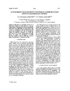
These systems are incompatible due to differences of implementation such as: interfaces among components, cryptography algorithms, and types of handoff [15]. However, common functional behaviors and architectural elements can be identified among mobility, communication and radio resource management functions. The main motivation for the identification of commonalities among these systems arises from the need of reusing good solutions in the development and evolution of mobile systems. The recognition of commonalities also leads to a clear identification of the differences among these systems and to a better way to make them interwork. In addition, the representation of the relationships between these solutions show how these commonalities work together (see Figure 2). In our work, we concentrate on commonalities related to mobility and radio resource management functions as shown in the next sub-sections. These commonalities are general and abstract enough to allow freedom with respect to future implementation decisions. A designer chooses solutions that best suit the system needs and adds the specific behavior and structure of the system. COMMON ARCHITECTURAL ELEMENTS To help readers and designers visualize a possible environment where the identified common solutions can be applied, Figure 1 depicts a simplified mobile system architecture. The following common architectural elements are identified among the previously mentioned second generation systems: mobile terminal (represented as a car), base station controller, security database, home database, mobile switching center, and visitor database. At the implementation stage (out of our scope), these elements, which represent network entities [2][29], can be combined in one or more physical entities.
Security Database
Home Database
Mobile Switching Visitor Database Center Base Station Controller
Location Area Figure 1. Common Architectural Elements As shown in the figure, the environment is divided into cells. Each cell covers a geographical area with a base station transceiver that supports the radio resources related to the use of the allocated spectrum. A location area contains several cells and a mobile switching center, which is responsible for the communication between the mobile terminal and the network. The base station controller is responsible for a set of base station transceivers and the connection between them is through the radio access ports. Many mobile terminals share a base station transceiver. Databases such as security database, home database and visitor database are responsible for keeping information about mobile users’ location, identification, authentication keys, services, and equipment.
In a typical mobile wireless environment, the network controls the provision of a dedicated channel to the mobile terminal over the radio interface. The main concern of the network is how to maintain this dedicated channel despite the wanderings of the users. A handoff function (also called handover in the literature) is responsible for this maintenance [7][14][15][23]. Base station transceivers and base station controllers are important components of the handoff process; however, this work considers only the handoff that generates network traffic and involves different mobile switching centers (called inter-system handoff). At the upper layers, the inter-system handoff is managed by mobile terminals (MSs) and mobile switching centers (MSCs). Base stations act as complex transmission systems. This handoff also requires specialized signaling protocols between the current and the candidate mobile switching centers involved. COMMON FUNCTIONAL BEHAVIORS WITH UNBOUND UCMS Figure 2 presents the relationships between common functional behaviors that are identified among mobility and radio resource management functions of the mobile systems mentioned in the previous section. The UCM paths show how these commonalities work together and each static stub represents a common functional behavior.
(b) Radio Resource Management (RRM)
(a) Mobility Management (MM) SMM
SRRM
checkAuth [NoNeed]
HandoffDecision
Cipher
Auth
[Need] Handoff
[Suc]
[Unsuc]
checkRegistration
[Unsuc]
[Suc] E1MM
[RegOk] Location
HandoffFailure
RelResources [RegNok]
[Release]
[HandSuc]
[Abort]
[HandFail] E1RRM
E2RRM
E3RRM
TMUIAssign E2MM
Figure 2. Common Functional Behaviors with Unbound UCMs The stubs shown in Figure 2 encapsulate the following solutions for mobility and radio resource management problems: authentication (Auth stub), ciphering (Cipher stub), location registration (Location stub), temporary identification assignment (TMUIAssign stub), handoff decision (HandoffDecision stub), inter-system handoff execution (Handoff stub), handoff failure actions (HandoffFailure stub), and releasing resources (RelResources stub). In Figure 2b, the following pre-condition associated with the SRRM start point triggers the common solution for radio resource management: the quality of the current radio link when a user is roaming is below threshold and a handoff measurement has been requested. The UCM flow from one stub to another represents potential sequences in which these common solutions can occur. The next stub in the sequence is chosen according to successful or
unsuccessful outcomes during the execution of the previous stub (e.g., the inter-system handoff is performed after a handoff decision to change the current radio link). Each stub can be also applied individually (see common solutions represented by plug-ins in Figure 3 and Figure 4) in conformity with design decisions of different systems. The responsibilities in Figure 2a are activated along the path to decide whether the mobile station is, respectively, authenticated and registered at the current location area. Alternative sub-paths are generated after these decisions. Figure 3 illustrates scenarios for mobility management solutions with unbound UCMs. These maps are bound to the stubs presented in Figure 2a. More details about mobility management solutions can be found in [3], which textually describes them. The authentication solution prevents unauthorized or fraudulent access to cellular networks by mobile terminals illegally programmed with counterfeit identification and electronic serial number. The unbound map depicted in Figure3a is triggered when the network side or the (a) Authentication SAuth
(c) Location Registration
(b) Ciphering
SLoc
SCipher
sendAuthInfo
sendKey cipherData
applyAuthAlg chkAuthRes [Unsuc]
[Suc]
notifyUnsuc
E2Auth
[Unsuc]
E2Cipher
[Suc]
E1Cipher
E1Auth
[Roaming] updHome
(d) Temporary Identification Assignment STempID
getLocInfo chkLoc [NotRoaming] updHome
UpdTemp delPrevTemp
ELoc
reqTempID [Unsuc]
E2TempID
chkTempID [Suc]
E1TempID
Figure 3. UCM Plug-ins for Mobility Management Stubs mobile user side requests the authentication. A triggering event described in the SAuth start point (e.g., when a power-on event or a change of location area occurs) represents this request. After this, the result of an authentication operation performed by the mobile terminal is sent to the network (the “send Authentication Information” responsibility). Then, the “apply Authentication algorithm” responsibility performs the same authentication operation at the network side. Alternative paths (called Orforks) represent UCMs that can be split into two different paths. For instance, the “check Authentication result” responsibility generates successful or unsuccessful outcomes (respectively, E1Auth or E2Auth end points) depending on the outcomes of the comparison between the respective results. In the case of denied authentication, the mobile user is notified. Otherwise, a successful authentication occurs and a resulting event is generated. The ciphering solution protects the privacy of the communication over an insecure wireless communication channel. As illustrated in Figure3b, this function is responsible for starting a ciphered communication over the air interface (ciphering and deciphering the data information). The “ciphering data” responsibility ciphers the data that is sent by the mobile terminal and the network deciphers it. The ciphering key, which is obtained by the “send ciphering key” responsibility, and the respective ciphering algorithm are used in the ciphering/deciphering procedure. This ciphering functional behavior starts when the network sends a ciphering mode request to a mobile terminal (SCipher start point). The change to the ciphering mode ends successfully ([Suc] path) after the network and the mobile terminal agree upon the ciphering/deciphering procedures (i.e., mobile terminal acknowledge the use of ciphering/deciphering). Otherwise, the map exits at the [Unsuc] path. The location registration solution keeps up to date information about a mobile user’s location
every time the user changes location area. Figure3c describes the Location Registration map that is triggered when the mobile user roams and needs to be registered in the current location area (SLoc start point). After getting the location information, the “check Location” responsibility generates different outcomes according to the following post-conditions: either the mobile user is visiting a new location area (both visitor and home databases are updated) or not (just the home database is updated). When the user is roaming, the “update Temporary user Profile” responsibility is an operation on the visitor database records. The “update home user Profile” responsibility is performed whether the user is roaming or not. Sub-paths labeled [Roaming], which means the user is visiting a location area , and [NotRoaming], which means the user is in her home location area, are joined to perform the location cancellation. The purpose of the location cancellation is to delete the user profile in the location area previously visited by the mobile terminal. The temporary profile is deleted from the previous visiting database (the “delete previous temporary user profile” responsibility in the figure). Unsuccessful outcomes are not shown in the figure but they can occur due to network or database failures. The Temporary identification solution ensures privacy of the subscriber’s identity when sending it on the radio path. The Temporary identification assignment map depicted in Figure3d is triggered when a mobile user powers on a mobile terminal or a mobile terminal changes location area (two different triggering events of the STempID start point). First, the mobile terminal sends its current temporary identification and the network assigns a new temporary identification (the “assign Temporary Identification” responsibility) and sends to the mobile terminal. Then, the “check the assigned Temporary Identification” responsibility checks whether the mobile terminal gets this temporary identification or not. This responsibility generates successful or unsuccessful outcomes (respectively, E1TempID or E2TempID end points) depending on different outcomes. If the confirmation is not received by the network, the operation is not successful ([Unsuc] path). Otherwise, the network completes this assignment successfully ([Suc] path). Radio resource management functions are performed by mobile systems when a dedicated radio communication channel has been assigned between the mobile terminal and the mobile switching center. Furthermore, they are applyed when the mobile user is roaming from one place to another. This possibility of changing cells (and consequently location area) is the major source of complexity for mobile networks [14][23]. Figure 4 illustrates the handoff decision and the inter-system handoff solutions with unbound UCMs. In this paper, the handoff failure actions and releasing resources solutions are not shown (respectively, HandoffFailure and RelResources stubs). (a) Handoff Decision
(b) Inter-System Handoff Execution S Hand
S HDecision
[Need]
takeMeasur
allocateChan tuneNewChan
compareMeasur
verifyChan
[NoNeed]
[Unsuc] [Suc]
E 1 HDecision
E 2 HDecision
E 2Hand
E 1Hand
Figure 4. UCM Plug-ins for Radio Resource Management Stubs
The handoff decision pattern solution controls the quality of the radio communication link between the mobile terminal and the network. The decision is taken according to measurements represented by the “take measurements” responsibility in Figure 4a. After this, a comparison is done (the “compare measurements” responsibility). The E1Hdecision and E2Hdecision end points represent the need of having a handoff or not. The inter-system handoff solution continuously guarantees communication service assessment for mobile users. Figure 4b starts with a handoff request triggering event (SHand start point). After this, a new channel is allocated. The mobile terminal tunes to the new channel. The new channel is verified to guarantee that the new link has better quality of transmission than the previous one. Alternative sub-paths labeled [Suc] and [Unsuc] are generated as a result of this action. In case of negative result, the resulting event of the E2Hand end point triggers the HandoffFailure stub shown in Figure 2b. In case of positive result, the RelResources stub is triggered (see also Figure 2b). 4 APPROACH FOR REUSE AND VALIDATION Requirement and analysis models are often used in the software engineering domain to describe systems at the early development stages [22]. The requirements capture step describes the system objectives as well as the user’s needs and encourages the thinking process in terms of generic behavior. The analysis and design steps comprise the static structure, the sequence of interactions that describe the problem to be solved in terms of entities (e.g., objects or functions), and the data transformations. On the other hand, the development process of telecommunication standards and services often comprises three major stages as illustrated in Figure 5 [2]. This three-stage methodology was first developed by ITU-T to describe services and protocols for ISDN. Subsequently, it has become of general use in the telecommunication area. Services are first described from the user’s point of view in prose form and with tables (stage 1). After this, they are expressed with information flows (also known as sequence diagrams or Message Sequence Charts (MSCs) [21]) that represent the sequences of messages between the different architectural elements involved in the communication (stage 2). Finally, they are expressed with (informal) specifications of protocols and procedures (stage 3). Stage 1
Stage 2
Stage 3 IF
Requirements
Information Flows
ENDIF ELSE
Protocols & Procedures
Stage 1: : Informal Service Descriptions Stage 2: : Message Sequence Information i and ) Procedure Specifications Stage 3: (SProtocol
Figure 5. ITU-T Three Stage Methodology This work introduces an approach to reuse and to validate commonalities when developing or maintaining mobile systems. The proposed approach combines UCMs and LOTOS notations at the requirements and analysis stages as shown in Figure 6. Unbound UCMs are applied at the requirements stage and bound maps at the analysis stage. These UCMs are translated into the LOTOS notation for the validation part. In addition, the proposed approach introduces commonalities, UCMs and LOTOS into the ITU-T three-stage methodology, as illustrated in Figure 6 (compare with Figure 5). UCMs
describe stage 1 documents (functional behaviors) and bridges the gap between stage 1 functional behaviors and stage 2 sequence diagrams with the mapping of functional behaviors to architectural elements. Our approach follows the Specification-Validation Approach with LOTOS and Use Case Maps (SPEC-VALUE) presented in [1] for the validation part. SPEC-VALUE is a rigorous scenario-driven approach for the description and validation of complex system functionalities at the early development stages. UCMs capture functional requirements and, at the design stage, the UCM scenarios are translated into detailed LOTOS specifications that are validated with the help of tools. The validation testing approach introduced in SPEC-VALUE proposes the generation of test cases at the design stage from the information provided by the users’ requirements.
Reuse Stage 1 Legend is reused by
Validation Common Solutions
Requirements
… Validation Test Cases
provides information to is generated from
+
Requirement Model Unbound Use Case Maps
LOTOS Specification Analysis Model Bound Use Case Maps
Bridge of Stage 1 and Stage 2
Figure 6. Approach for Reuse and Validation In our case, the validation consists of functionality-based test cases generated in LOTOS starting before the design stage. These test cases are generated from the common solutions and from the system requirement model that also contains specific system behaviors. The LOTOS specification, which is a system prototype, is derived from the UCM requirements and analysis models. This specification is then validated against the test cases using the LOLA tool. The goal is to guarantee that the prototype is in conformance with the requirements before reaching the design stage. Similar to the SPEC-VALUE approach, there is no formal method for the generation of these test cases. Although not illustrated in the figure, different cycles are used to allow the system behavior increases with designer and user needs. Each development cycle brings additional details regarding new functional requirements as well as new system components (called variabilities in [12]). This incremental characteristic is useful when developing a large system. For instance, functionalities can be described at different development cycles, as follows: mobility management functions are described in the development cycle 1, followed by communication and radio resource management functions in the development cycle 2 and development cycle 3, respectively. Besides this, if any modifications are required after validating the prototype generated with LOTOS, it is possible to revisit the respective model for several iterations. In this case, the informal description as well as the requirement and analysis models may be revisited for several iterations.
The next sub-sections present details of the reuse and validation steps. REUSE WITH UCMS The first decisions regarding functional behaviors and architectural elements to be added to the system are taken at the requirements and analysis stages, respectively. The reuse is done at the requirement stage (ITU-T stage 1) where the required functionalities are extracted from the set of common solutions for mobility and radio resource management that we have identified among the chosen systems. As mentioned in Section 3, commonalities are graphically specified with UCMs in a general and abstract way to allow telecommunication designers to reuse them at stage 1. They offer a common development foundation to mobile systems’ designers. Since the focus is on the early stages, designers can adapt and make changes according to the system needs. Figure 6 illustrates the requirements and analysis stages with the reuse of common solutions and the generation of validation scenarios. The resulting models (requirements and analysis models) generated at these stages are also depicted in the figure. Plain gray arcs represent the reusability process. Functional behaviors and architectural elements are reused at the requirements and analysis stages, respectively. Black arcs express the capture of information from the requirements and requirements model to graphically specify unbound and bound UCMs. The derivation of the validation scenarios from the solutions described by unbound and bound UCMs is also part of the reusability process (see dashed gray arcs in the figure). In order to avoid ambiguities caused by the narrative documents and tables used in the ITU-T stage 1, UCMs are used to describe requirements (the requirements model shown in Figure 6). At the beginning, when details about architectural elements (e.g., the network reference model shown in Figure 1) are not available, unbound UCMs are specified. Decisions regarding which system component is responsible for a specific action or event are taken during the analysis stage. The architectural elements come into play at this point and a network reference model is described with UCM components. The functional behavior (represented by the requirements model) is then mapped to the network reference model. Bound UCMs that constitute the analysis model are the result of this mapping. Detailed descriptions about what the system does are represented in terms of new stubs and plug-ins, responsibilities, which are refined with pre- and post-conditions, start points, which are refined with pre-conditions and triggering events, and end points, which are refined with post-conditions and resulting events. Figure 8 depicts the inter-system handoff plug-in with new responsibilities (compare with Figure 4b). VALIDATION WITH LOTOS Validation and verification techniques cannot be used directly with the UCM notation because of its informality. On the other hand, such techniques are available in LOTOS, and are supported by tools. LOTOS was used as the formal underlying model that supports UCMs. At the analysis stage, a LOTOS prototype is specified on the basis of the requirement and analysis models. To do this, construction guidelines (CG) are taken from the SPEC-VALUE approach [1]. At the design stage (not the focus of this paper), details about exchanged messages, parameters and data types are added. In this paper, the use of LOTOS, which starts in the analysis stage, reduces the semantic gap
between the translation of UCM requirements and analysis models to LOTOS at the design stage. As a result, when the LOTOS specification is validated, several aspects of the UCM notation are also validated including: causal sequences of responsibilities, choice relations, enabling relations, disabling relations, join relations, and parallel relations. Our validation part focuses on the reuse of common solutions in the specifications. In order to specify systems and their validation test cases with LOTOS, the following mapping is done from the UCM notation to the LOTOS operators: •
At the requirement stage, each plug-in is mapped to LOTOS processes as depicted in Figure 7. At the analysis stage, UCM components are mapped to LOTOS processes. Figure 8 illustrates part of the specification in UCMs and LOTOS, which constitute analysis models, to address the communication between the MSC and the HLR processes (respectively, mobile switching center and home database in Figure 1). When a UCM path crosses a component as shown in Figure 8, we use the LOTOS gates to represent an interaction with the environment or with other processes;
•
LOTOS process behavior corresponds to the causality sequence of responsibilities. The translation is straightforward at the requirement stage; however, the responsibilities for each UCM component are not always included in one single map when generating the analysis model.
SRRM [NoNeed] HandoffDecision [Need] Handoff [Unsuc]
[Suc]
HandoffFailure
RelResources [HandSuc] E1RRM
[Release] [HandFail]
E2RRM
[Abort] E3RRM
behavior … start !RRM; (* start point *) (HandoffDecision [start, resp, end] >> (Handoff[start, resp, end] >> (RelRes[start, resp, end] >> (end !E_RRM1; exit)) [] (HandoffFailure[start, resp, end] >> (RelResources[start, resp, end] >> (end !E_RRM2; exit)) || (end !E_RRM3; exit)) [] (end !E_RRM1; exit)) ) where process HandoffDecision [start, resp, end] :exit := … Endproc …
Figure 7. From unbound UCMs to LOTOS
•
the action prefix operator “;” used as in “a;B” means that an action on gate “a” precedes a behavior “B” This translates sequences of responsibilities as illustrated in Figure 7.
•
the choice operator “[]” used as in “B1[ ]B2” means that the process will behave as either “B1” or “B2”. This translates choices among paths in the UCM represented by the ORForks or by stub alternatives as shown in Figure 7.
•
the disable operator used as in “B1[>B2” means that at any time during the execution of “B1”, “B2” can be triggered and terminate “B1”. This translates zigzag abort paths in the UCM (not shown in this paper).
•
the enable operator used as in “B1>>B2” means that “B2” can only be activated after the successful completion of “B1”. This translates concatenation of maps as depicted in Figure 7.
•
the guard operator used as in “[P]->B” means that “B” can only be performed if the predicate “P” is true. This translates conditions on choices of paths (OR-Forks) and solves non-determinism problems associated with choices (not shown in this paper).
•
the full synchronization parallelism operator used as in “B1||B2” means that “B1” and “B2” must synchronize in every action that they perform (see Figure 7);
•
the interleaving operator used as in “B1|||B2” means that “B1” and “B2” are performed in parallel without any synchronization between them;
•
the interleaving operator used as in “B1|[g1,g2, …, gn]|B2” means that “B1” and “B2” are performed in parallel with synchronization required on the gates g1,g2, …, gn. Figure 8 shows the MSC and HLR synchronization through the gates hlr_to_msc and msc_to_hlr.
The last three parallel composition operators translate situations where there are concurrent paths in the UCM (AND-Forks). LOTOS parallelism allows more than one instance to execute concurrently and for execution purposes, we limit the maximum number of instances using ADTs. SHand
MSC allocateChan
tuneNewChan verifyChan [Unsuc]
verifyChan [Suc]
E2Hand
HLR updProfile
tunePrevChan
[Unsuc]
[Suc]
updTempProf
behavior … (MSC [ms_to_msc, msc_to_hlr, hlr_to_msc …] (msc1) |[hlr_to_msc, msc_to_hlr]| HLR [msc_to_hlr, hlr_to_msc] (hlr1, initialHLRset1) … process MSC [ms_to_msc, msc_to_hlr, hlr_to_msc …] … endproc process HLR [msc_to_hlr, hlr_to_msc, …] … endproc
VLR
E1Hand
Figure 8. From bound UCMs to LOTOS It is also important to mention that UCM timeouts are described in LOTOS as explicit internal actions (messages) to be executed if no triggering event comes from the environment. Our validation purpose is to execute the specification against acceptance test cases that describe the pattern solutions (i.e., commonalities). Our intention is to assure that the common solution is well captured in the requirements and analysis models. In short, we validate the specification against the solutions to guarantee that these solutions are preserved in the specification with the addition of new behavior and structure (called variabilities in [12]). However, this kind of validation does not guarantee that the solution is reused properly in the specification that contains commonalities and variabilities. This case is validated with test cases that cover complete scenarios on the basis of the requirements and analysis models.
Figure 9 depicts an example of validation test cases that are LOTOS processes derived from the common solutions. These test cases are composed with the LOTOS prototype to detect possible errors. process Hand_1 [start,resp,end, success] :exit:= start !S_Hand; resp !allocateChan; resp !tuneNewChan; resp !verifyChan; (*[Unsuc] *) end !E2_Hand; success;stop endproc Validation Scenario 1
process Hand_2 [start, resp, end, success] :exit:= start !S_Hand; allocateChan resp !allocateChan; resp !tuneNewChan; verifyChan resp !verifyChan; (*[Suc] *) [Suc] end !E1_Hand; success; stop endproc
SHand
tuneNewChan
[Unsuc]
Validation Scenario 2
E2Hand E1Hand
Figure 9. Validation Test Cases from Handoff Common Solution The successful termination of a test case means that the termination event (e.g., success in the figure) has been reached. Unsuccessful test cases represent the case of not reaching the terminating event due to deadlocks or internal livelocks. One of the following results may be obtained with the LOLA tool: must pass, may pass, or reject. Must pass and may pass are considered successful results that guarantee a good level of confidence in the reuse of the solutions with the new behaviors, which are introduced in the specification. When a test case fails, the functionality, which has been tested, contains a logical error (reject result). As mentioned in [1], this functional behavior was incorrectly specified according to the UCMs or was incorrectly integrated with the others. 5 CONCLUSION We have presented the concept of pattern solution, together with an approach for reuse and validation of pattern solutions for mobile systems at the requirements and analysis stages. These solutions become easily understood to novices and experts alike by means of graphical specification with UCMs. The validation test cases are generated in LOTOS from these UCMs. As mentioned earlier, the formal specification and validation with LOTOS provide confidence in the correctness of the reuse of these patterns. The common solutions for mobility and radio resource management functions were described in a general way, capable of different implementations. In practice, problems and their respective solutions were recognized by investigating different mobile systems and by capturing what they have in common. These commonalities were identified by abstracting from the solutions used in various systems, such as GSM and ANSI-41 based systems as well as WmATM systems, and looking for similarities. Whether designers are maintaining existing systems or building new ones, they can identify what makes their actual or future systems different based on the set of solutions that capture the common behaviors and architecture of legacy systems. Once one recognizes commonalities among existing systems, it is possible to iron out differences and enable them to interwork. The graphical specification of the requirement and analysis models with unbound and bound
UCMs, respectively, allows the designer to have an overview of how a typical mobile system works from the early stages of the development and maintenance processes. Unbound UCMs with their focus on causality and responsibilities without reference to the structure of components have proved to be very useful for early descriptions of service functionalities [1][4][5]. When the architectural structure is available, components can be easily added to the functional maps. In this case, bound UCMs are generated. This paper presents only some of the common solutions that can be identified and documented among mobile systems. More commonalities related to architectural elements and other functionalities might be identified in the future. Furthermore, a generic framework can be generated to represent the relationships between the common solutions and to show how these commonalities work together. As future work, we aim to add the design model to our approach and to translate the validation results to the MSC notation [21]. MSCs allow us to represent clearly the results of the LOLA validation activities. Successful and unsuccessful MSC scenarios can be more readable and attractive than LOTOS traces. In addition, these MSCs can become stage 2 documents, which are currently used by implementers to generate the protocols. In [5], we have shown how a simplified Wireless mobile ATM network (WmATM) can be validated using LOTOS [16] and how the validation results can be translated to the MSC notation. However, the reusability process was not applied to this WmATM example. ACKNOWLEDGEMENTS We would like to thank the University of Ottawa’s LOTOS Group for their support and useful comments, especially Jacques Sincennes, Ruoshan Guan and Leila Charfi. We also acknowledge UFC, CAPES, CITO, and NSERC for their financial support. REFERENCES 1. Amyot, D. and Logrippo, L., “Use Case Maps and LOTOS for the Prototyping and Validation of a Mobile Group Call System,” Computer Communications 23, Special Issue on FDTS, 1135-1157, 2000. 2. Amyot, D., Andrade, R., “Description of Wireless Intelligent Networks with Use Case Maps”, In: Proc. Brazilian Symposium on Wireless Networks (SBRC 99), 418-433, Salvador (BA), Brazil, 1999. 3. Andrade, R., Bottomley, M., Logrippo, L., Coram, T., “A Pattern Language for Mobility Management”, In: Proc. of the 7th Conference on the Pattern Languages of Programs (PLoP 2000), Monticello, Illinois, 2000. 4. Andrade, R., and Logrippo, L., “Reusability at the Early Development Stages of the Mobile Wireless Communication Systems”, In: Proc. of the 4th World Multiconference on Systemics, Cybernetics and Informatics (SCI 2000), Orlando, Florida, 2000. 5. Andrade, R., “Applying Use Case Maps and Formal Methods to the Development of Wireless Mobile ATM Networks”, In: Proc. of the Fifth NASA Langley Formal Methods Workshop, Williamsburg, Virginia, 2000. 6. ANSI/TIA/EIA ANSI-41-D, Cellular Radiotelecommunications Intersystem Operations, 1997. 7. Black, U., Second Generation Mobile & Wireless Networks, Prentice Hall Series in Advanced Communication Technologies, Prentice-Hall, Inc., 1999. 8. Bolognesi, T., and Brinksma, E., “Introduction to the ISO Specification Language LOTOS” In: P.H.J. van Eijk, C.A. Vissers, M. Diaz (Eds) The Formal Description Technique LOTOS. Elsevier, 1989, 23-73. 9. Bolognesi, T., van de Lagemaat, J., and Vissers, C., Lotosphere: Software Development
with Lotos, Kluwer Academic Publishers, 1995. 10. Bora A., “Signaling Alternatives in a Wireless ATM Network,” In: IEEE Journal on Selected Areas in Communications, Vol. 15, No. 1, January 1997. 11. Buhr, R. J. A, “Use Case Maps as Architectural Entities for Complex Systems”, In: IEEE Transactions on Software Engineering, Special Issue on Scenario Management, Vol. 24, No. 12, December 1998. 12. Coplien, J. O., Hoffman, D. M., Weiss, D. M., “Commonality and variability in software engineering, IEEE Software, 15(6), 37-45, 1998. 13. Fang-Cheng and Holtzman, J. M., “Wireless Intelligent ATM Network and Protocol Design for Future Personal Communication Systems,” In: IEEE Journal on Selected Areas in Communications, Vol. 15, No. 7, September 1997. 14. Gallagher, M. D., Snyder, R. A., Mobile Telecommunications Networking with IS-41, McGraw-Hill, 1997. 15. Grinberg, A., Seamless Networks: Interoperating wireless and wireline networks, Addison-Wesley, 1996. 16. Hoare, C. A. R., Communicating Sequential Processes, Prentice-Hall International, 1985. 17. ISO/IEC, “Enhanced LOTOS”, ISO/IEC 15437, 2000. 18. ITU-T, “Q1701 Recommendation: IMT-2000 Systems Framework,” March 1998. 19. ITU-T, “Q1711 Recommendation: IMT-2000 Systems Signaling Requirements,” 1998. 20. ITU-T, “Q1721 Draft Recommendation: IMT-2000 Systems Information Flows,” 1999. 21. ITU-T, Recommendation Z. 120: Message Sequence Chart (MSC), Geneva, 1996. 22. Jacobson, I. et. al, Object-Oriented Software Engineering (A Use Case Driven Approach), ACM Press, Addison-Wesley, 1992. 23. Logrippo. L., Faci, M., Haj-Hussein, M., “An Introduction to LOTOS: Learning by Examples,” Computer Network and ISDN Systems 23, 325-342, 1992. 24. Miga, A., Application of Use Case Maps to System Design with Tool Support, M.Eng. Thesis, Dept. of Systems and Computer Engineering, Carleton University, Ottawa, Canada, 1998. 25. Milner, R., Communication and Concurrency, Prentice-Hall, New York, 1989. 26. Mouly, M. and Pautet, M.-B., The GSM System for Mobile Communications, 1992. 27. OSI - IS 8807, “Information Processing Systems - Open Systems Interconnection LOTOS - A Formal Description Technique Based on the Temporal Ordering of Observational Behaviour”, International Standard IS 8807 (E. Brinksma, ed.), 1989. 28. Pávon, S., Larrabeiti, D., and Rabay, G., “LOLA – User Manual,” version 3.6. DIT, Universidad Politécnica de Madrid, Spain, LOLA/N5/V10, 1995. 29. TIA/EIA Wireless Intelligent Networks (WIN), Additions and modifications to ANSI-41 (Phase 1), TR-45.2.2.4, PN-3661 Ballot Version, May 1999. 30. Use Case Maps Web Page: http://www.UseCaseMaps.org, since 1999.