Software—Concepts and Tools (1995) 16: 170–182
Software—Concepts and Tools © Springer-Verlag 1995
Reverse Engineering by Visualizing and Querying Alberto Mendelzon Computer Systems Research Institute, University of Toronto, Toronto M5S 1A1, Ontario, Canada e-mail:
[email protected]
Johannes Sametinger Department of Computer Science, Texas A&M University, College Station, Texas 77843-3112, USA e-mail:
[email protected]
A b s t r a c t . The automatic extraction of high-level structural information from code is important for both software maintenance and reuse. Instead of using specialpurpose tools, we explore the use of a general-purpose data visualization system called Hy+ for querying and visualizing information about object-oriented software systems. Hy+ supports visualization and visual querying of arbitrary graph-like databases. We store information about software systems in a database and use Hy+ for analyzing the source code and visualizing various relationships. In this paper we demonstrate the use of Hy+ for evaluating software metrics, verifying constraints, and identifying design patterns. Software metrics can be used to find components with low reusability or components that are hard to understand. Checking the source code against constraints can help bring design flaws to light, eliminate sources of errors, and guarantee consistent style. Identifying design patterns in a software system can reveal design decisions and facilitate understanding the code. We conclude that the flexibility achieved by using a generalpurpose system like Hy+ gives this approach advantages over special-purpose reverse-engineering tools, although specialized tools will have better performance and more knowledge of specific software engineering tasks. Combining the advantages of the two approaches is an interesting challenge.
Keywords: reverse engineering, visualization, query, software metrics, constraints, design pattern, objectoriented programming, database, Hy+, GraphLog
1. Introduction Program comprehension plays a major role in software maintenance. The increased reuse of software components, facilitated and supported by objectoriented programming, makes program comprehension even more important as existing software must be understood during both development and maintenance.
Very often the only information a programmer can trust is the source code. It is the only accurate, complete and up-to-date representation of a program. However, source code listings are hardly suited to represent design decisions, global system structure or interactions among components. The extraction of high-level structural information from code, called reverse engineering [2], is important for both software maintenance and reuse. Analyzing the source code can help to find components with certain properties, to find possible bottlenecks and weak points of a system, to identify components and their relationships, and to better reconstruct the chain of reasoning of the original authors. Software metrics can be used to find components with low reusability or components that are hard to understand. Checking the source code against various constraints can help to bring design flaws to light, to eliminate sources of errors, and to guarantee consistent style. Identifying design patterns in a software system can reveal important facts about the design. A large amount of information together with complex relationships among various objects characterizes most of today’s software systems. Tool support is indispensable for successful analysis. Instead of developing several tools for the various activities mentioned above, we have used a general-purpose tool for visualizing and querying software structure. Besides saving the effort of developing separate tools, this has the advantage that a general-purpose tool can easily be extended for future applications. We chose the Hy+ and GraphLog system [13] because of its power and high flexibility. In this paper we demonstrate the power of visualizing and querying in the reverse engineering domain by applying the Hy+ visualization system and GraphLog visual query language to the specification of metrics, constraints and design patterns. In Section 2
Mendelzon, Sametinger: Reverse Engineering by Visualizing and Querying
we introduce Hy+ and GraphLog. In Section 3 we discuss software metrics, in Section 4 constraints, and in Section 5 design patterns. Section 6 defines the database, and Section 7 offers conclusions.
2 . Hy+ and GraphLog The Hy+ system is a generic tool for visualizing objects and relationships among them. Hy+ supports a novel visual query language called GraphLog. Hy+ provides a user interface with extensive support for visualizing structural (or relational) data as hygraphs [8], an extension of graphs inspired by Harel’s higraphs [12]. For simplicity, in this paper we only use standard directed graphs, a subset of the hygraph formalism. The Hy+ system supports visualization of the actual database instances, not just diagrammatic representations of the database schema. The use of a query language is essential in making this approach scale up to large database instances. This is accomplished in two ways. First, Hy+ allows the user to define new relationships by using queries. This is the traditional way of using database queries: the newly defined relationship either gives a direct answer to a user question, or it provides a new view on the existing data. The derived data can later be presented visually by the system. In this way, users can abstract irrelevant details or aggregate information into visualizations of manageable size. Second, in Hy+ the user can employ queries to decide what data to show. The user can selectively restrict or filter [8] the information to be displayed. Selective data visualization can be used to locate relevant data, to restrict visualization to interesting portions of the data (that is, to decide which data to present), and to control the level of detail at which the data is presented (that is, to choose how to see the data). Hy+ supports a visual pattern-based notation for the specification of queries. The patterns are expressions of the GraphLog query language. We give a short introduction to GraphLog here; a full definition can be found in [5, 6]. In the remainder of the paper we introduce the basic functionality of GraphLog through examples. These examples demonstrate the application of GraphLog to compute software metrics, verify constraints, and find design patterns in a database describing the structure of an object-oriented software system. Hy+ databases are graphs whose nodes are labeled with ground terms and whose edges are labeled with predicates. Database instances of the object-oriented or relational model can be visualized easily as graphs. For example, an edge labeled p(X ) from a node labeled T_1 to a node (containing a node) labeled T_2 corresponds to the tuple (T_1, T_2, p(X )) of relation p in the relational model. No key is associated with the relation p.
171
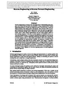
For example, suppose we have a database containing all classes and methods of some software system we want to explore. This database can be viewed with Hy+ as a graph in which the nodes represent software objects such as classes and methods and the edges represent relationships. A node is labeled with a Prolog-like term in which functors are used for typing purposes. For example, a method node might be labeled with a two-place functor method(Name, Class) giving the name of the method and the name of the class in which it appears. Methods with the same name appearing in different classes will be represented by different nodes. Edges are labeled by predicates of the form p(F1, ..., FN), where the Fi’s are terms. The meaning of a predicate p(F1, ..., FN) between a node labeled F and a node labeled G is the literal p(F, G, F1, ..., FN). The frequent case where relationships are binary and have no extra attributes is represented by labeling the edge with just the predicate name p. For example, each link in the inheritance hierarchy is represented by an edge labeled superclass between two classes. Additionally, a method edge exists to connect classes and their methods. Chapter 6 describes in more detail the contents of the database and how it is automatically constructed from the system’s source code. Hy+ provides different ways of visualizing such a graph and manipulating the visualizations; more information on this functionality can be found in [8]. Figure 1 shows a small portion of such a database. GraphLog queries are sets of graphs whose nodes are labeled with terms, and each edge is labeled with an edge label. Node labels can be more general than those in database graphs because they can include variables; edge labels may include not only variables but also regular expressions. An edge in a query graph may match a path in the database graph, where the labels along the path are constrained by the regular expression. There are two types of queries: define and filter. In both, the query hygraph represents a pattern; the query evaluator searches the hygraph designated as the database for all occurrences of that pattern. The difference between the two types of queries stems from their interpretation of distinguished elements, explained below. A hygraph pattern in a define query (which is enclosed in a defineGraphLog box) must have only one distinguished edge labeled by a positive literal. The meaning of the [define] query hygraph is to define the predicate in this distinguished literal in terms of the rest of the pattern. The semantics of define queries are given by a translation to stratified Datalog [5]. Each define graph translates to a rule with the label of the distinguished edge in the head and as many literals in the body as there are nondistinguished edges in the graph. Additional rules may be necessary to define the
172
Mendelzon, Sametinger: Reverse Engineering by Visualizing and Querying
Figure 1. Visualization of a sample database.
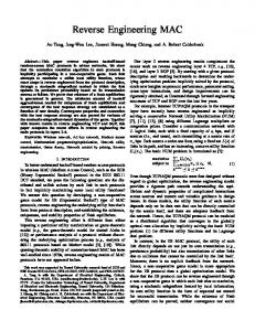
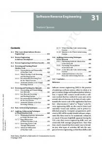
predicates of nondistinguished edges that are labeled by regular expressions. The generation of these additional rules is based on the structure of the regular expression. Figure 2 shows how the relation subclass can be defined using the relation superclass. A graph pattern in a filter query (which is enclosed in a showGraphLog box) may have several distinguished nodes and edges. The meaning of a filter query graph is: for each instance of the pattern found in the database, retain the database objects that match the distinguished objects in the query. Given a graph in a showGraphLog box, for each distinguished edge, we generate a set of define queries that match the distinguished object, that is, when they are evaluated they determine all instances of the edge that exist in the portions of the database that match the hygraph pattern. The query evaluator evaluates each of the define queries in turn. The results are combined, and the answer to the filter query is found. Figure 3 shows a very simple filter query. GraphLog can collect multisets of tuples and compute aggregate functions on them. The aggregate functions supported in GraphLog are the unary
Figure 2. Define query.
operators MAX, MIN, COUNT, SUM and AVG. They are allowed to appear in the arguments of the distinguished relation of a define query as well as in its incident nodes. As an example of the use of aggregation in GraphLog, consider the defineGraphLog box of Figure 4. It defines the relation coupled between two classes. The relation coupled (C1, C2, N)) is defined between C1 and C2 when class C1 has a total of N variables of type C2.
3 . Metrics Measures of the size and complexity of software systems are helpful for estimating costs and schedules, improving software quality, and anticipating and reducing future maintenance requirements [1]. Software managers desire software metrics for project planning and evaluation and for use in enforcing quality assurance. In the reverse engineering process, extracting measures from an existing software system can help in finding candidates for:
Figure 3. Filter query.
Mendelzon, Sametinger: Reverse Engineering by Visualizing and Querying
173
Figure 4. Aggregate function in a query.
•
•
•
components with low reusability Classes with a large number of methods are more likely to be application-specific and thus less reusable than others. If this is not the case, they might be candidates for redesign. components that require extensive testing Errors in leaf classes are more local than in classes with many children (subclasses). The greater the number of code lines in a method, the greater is the probability of an error in that method. components that are hard to understand Encapsulation is important for hiding details and prohibiting unallowed access to the details of certain components. Inter-object coupling should be kept to a minimum. Understanding and testing highly coupled classes tends to be more difficult.
Metrics oriented towards object-oriented systems can also aid in evaluating the degree of object-orientation. This becomes important in light of the need for many conventional programmers to switch to object-oriented thinking. Environments for the evaluation of metrics do exist. For example, ATHENA allows easy implementation of design and code metrics with a specially designed specification language [19]. We did not try to support the measure of well-known metrics like McCabe or Halstead. Their benefit in object-oriented systems is less important than in conventional ones because the complexity of these systems shifts from statements and functions to components and their interactions. With GraphLog’s ability to specify arithmetic expressions in queries, it is a rather straightforward process to evaluate various metrics. We will
demonstrate on a simple example how easy it is to extract measures from (both object-oriented and conventional) software systems. In object-oriented systems, dynamic binding complicates the comprehension process because sending a message can cause the invocation of many methods. Suppose we want to know all methods (and their corresponding classes) where a call can result in more than, say, 20 different method calls; i.e., we want to know whether a certain method is overridden in more than 20 subclasses, because tracing the control flow in that case is understandably difficult. Let us see how we could find such methods using Hy+ and GraphLog. To find methods that are overridden in more than 20 subclasses, suppose first that our database contains an edge labeled ovCount that connects each method M to a node labeled with the number of methods that override M. Then all we need to do is filter out from the graph those methods connected by an ovCount edge to an integer greater than 20. Figure 5 shows a filter query that does this.
Figure 5. Filtering methods with ovCount>20.
174
Mendelzon, Sametinger: Reverse Engineering by Visualizing and Querying
Figure 6. Result of the ovCount query.
Recall that a filter query is interpreted as a graph pattern; for each instance of the pattern found in the database, the distinguished (bold) objects are retained and displayed as part of the answer. In this example, the pattern requires methods M that are overridden by a number NR of methods, where NR>20; the distinguished object is just the ovCount edge. The answer, shown in Figure 6, will be a set of edges connecting all methods of interest to the count of methods that override them. Instead of just showing how many times each method is overridden, we would probably be interested in knowing in which classes the overrides occur. To see this, we simply add to the filter query another method node M2 and a distinguished overrides edge from M2 to M. To avoid a too complex answer for this paper, we additionally specify the method name Draw of class VObject instead of M in Figure 7, thus restricting the answer to overriding methods of this particular method. The answer, shown in Figure 8, will then show all the classes where each of the methods of interest is defined or redefined. In this case, we can see that method Draw of class VObject is overridden 32 times (ovCount). On the left side all the overriding methods are listed. We could add even more information by adding a separate showGraphLog box requesting that the subclass hierarchy also be displayed, as shown in the
left box of Figure 9. C1 is a direct or indirect subclass of class CompositeVObject; this relationship is indicated by the use of transitive closure in the regular expression subclass+. The transitive closure is drawn dashed to indicate that it may match a path of arbitrary length in the database, not just an edge. For the resulting nodes the subclass relationship is shown in the answer (indicated by the distinguished subclass relation to C2). And again we restrict the query to a certain subclass hierarchy (class CompositeVObject) in order to obtain an answer that is not too complex to be clearly shown in this paper. The answer is in Figure 10.
Figure 7. Extended filter query.
Mendelzon, Sametinger: Reverse Engineering by Visualizing and Querying
175
Figure 8. Result of filter query in Figure 7.
Unfortunately, the relations overrides and ovCount do not exist in our database. But with GraphLog we can easily define new relations based on existing ones. (This provides the flexibility to define arbitrary metrics.) Thus, in Figure 11 we define ovCount as being the number of methods M1 that override M2. Note that this is a define query. The distinguished object, i.e., the one being defined, is the ovCount relationship. This query also shows the use of aggregation, in this case to count, for each method M2, how many methods M1 override it. Finally, we define the relation overrides. A method in class C1 overrides another method in class C2 if both have the same name (without taking parameters
into account), and if C1 is a superclass of C2. This fact is expressed by drawing two classes (see Figure 12), each with a method named M. C2 is a direct or indirect superclass of C1, which is indicated by the use of transitive closure in the regular expression superclass+. And, of course, C1 and C2 have to be different. This is ensured by drawing a non-equals edge between them. The crossing-out of an edge is GraphLog’s general mechanism to indicate negation. As a result of the query described above, we obtain the graph shown in Figure 7. The methods are specified by method name and class name. Thus the methods PrintOn of class EvtHandler and ReadFrom of class VObject are overridden by 28 methods, and so on.
Figure 9. Filter query for additionally displaying the subclass hierarchy.
176
Mendelzon, Sametinger: Reverse Engineering by Visualizing and Querying
Figure 10. Result of the query specified in Figure 9.
Examples of metrics that can be specified in a very similar way include: • • • • • • • • •
methods per class depth of inheritance number of children (subclasses) coupling between objects response for a class lines of code (for classes, methods, functions, files) number of methods (for clients, heirs, friends) number of (instance) variables number of strongly coupled classes
These metrics are targeted at the source code only. It is often argued that monitoring metrics after coding is far too late in a software project. Hy+ enables shifting the
Figure 11. Definition of the relation ovCount.
focus to other software artifacts, e.g., requirement specification. However, it has not been our goal to provide a general software metrics tool with Hy+, but rather to use its flexibility for program comprehension and reverse engineering purposes. We have used Hy+ to extract measures from a large C++ class library in order to easily find out things listed above. The library (application framework) ET++ [20] was constructed by experienced programmers. Therefore it was not our goal to detect flaws but rather to support the comprehension process by visualizing the system structure and to give prominence to classes and methods with certain characteristics. On the other hand, querying student projects helped in locating sources of trouble, which were then discussed in order to improve the design and/or eliminate existing flaws.
Figure 12. Definition of the relation overrides.
Mendelzon, Sametinger: Reverse Engineering by Visualizing and Querying
4 . Constraints Most programming languages do not allow expression of many important constraints about our software systems. Such constraints contain design, implementation and stylistic conventions and are necessary to achieve improvement in software quality attributes like reliability, maintainability and readability. Automatic detection of violations can help to ensure style consistency across project or company and thus to eliminate a variety of sources of troubles. This is important as well in software maintenance and reverse engineering [3]. There are different ways to detect constraint violations. Assertions or annotations are available for various languages like Ada, Eiffel and C++. CCEL, the C++ Constraint Expression Language, is a very powerful language that allows users to specify and automatically detect violations of C++ constraints [15]. The following constraints are taken from [3, 14, 15], where they are explained in more detail. We list some examples for design, implementation, and stylistic constraints.
Design Constraints Design constraints are not specific to a certain programming language. They can, however, be specific to certain libraries and/or applications. Typical examples are: • • • •
Subclasses must not redefine inherited nonvirtual methods. A method in a certain class must be overridden in all subclasses of that class. A class should not have any public data members (encapsulation). Structures in C++ should not be used like classes; i.e., they should have only public members, no methods and no base class.
•
177
If there exist multiple public inheritance paths from a derived class to one of its base classes, then all these paths should be declared as virtual.
Stylistic Constraints Some set of naming conventions are adopted in almost all software projects. They are intended to increase the readability of software systems. Typical examples are: • • • •
Class and method names must begin with an upper case letter. Constants and global variables must begin with the lower case letters ‘c’ and ‘g’, respectively. Public, protected and private members of a class must be specified in this order. Variable (or any other) names may not contain any underscore characters (“_”) or two consecutive underscore characters (“__”).
The power of Hy+ and GraphLog depends on the database being queried. Basically, we can check against all constraints that can be specified, e.g., with CCEL. However, we must admit that for efficiency reasons we do not store as much information as would be necessary to compete with CCEL. But in contrast to CCEL we graphically define queries in order to find violations against various constraints. Additionally, we do not need a special language and a separate, constraint specific tool. We are also currently working on investigating the dynamic behavour of object-oriented software systems. Whereas CCEL is limited to checking static information, we will be able to process dynamic information as well. Finding stylistic constraints is rather trivial because in GraphLog we can use regular expressions. Figure 13 shows how to simply find classes which start with a lower case letter and therefore violate one of the stylistic constraints mentioned above. A more complex, but still simple example is how to find classes that redefine nonvirtual methods (design constraint). For this purpose we need the relation
Implementation Constraints Implementation constraints are design-independent. Violations against them can lead to incorrect program behavior. Thus it makes sense to have a closer look at locations where implementation constraints are violated. Typical examples are: •
• •
An assignment operator and a copy constructor must be defined for classes that declare a pointer member. Every base class should declare a virtual destructor. Every class with a constructor should declare a destructor and vice-versa.
Figure 13. Definition of classes with lower case letters.
178
Mendelzon, Sametinger: Reverse Engineering by Visualizing and Querying
overrides defined in Figure 12. In C++ it is sufficient (and necessary) that the first method in the inheritance path be declared as virtual. We define the relation overridesVirtual between a method M3 and a method M2 if M3 overrides M2 and M2 overrides another method M1 which is virtual (see Figure 14). The attributes node contains information about a method; virtual(yes) indicates that the method has been defined as virtual. Next, we can simply define the relation overridesNonVirtual (see Figure 15). Method N overrides a nonvirtual method M when N overrides M and the relation overridesVirtual does not hold between M and N. We have been rather successful in checking student projects against constraint violations. This is not surprising. For example, our students liked to have public data members, hardly ever implemented a copy constructor or an assignment operator, and sometimes failed to clean up their systems with destructors. This has become better now, because we explicitly mention these points in the lectures. However, one of the amazing facts was that there were constraint violations in the framework ET++ that could lead to incorrect program behavior, although the framework had been in use by many programmers for years. We found two classes with nonvirtual methods that were overridden in subclasses. Additionally, in ET++ classes, assignment operators are not defined. However, this is not a problem as long as all objects are declared as pointers. Nevertheless, users of the framework could run into troubles.
i.e., classes, becomes obsolete. Thus we tried to go one step further by identifying design patterns in a subject system. With patterns, piecework is standardized to larger units. For example, a symphony consists of single notes, but various patterns (which are wellknown to composers and other musicians) express the design of a piece of music. Software design patterns capture the intent behind the design of a software system. For example, a special arrangement of classes and/or objects might recur frequently in order to avoid reuse errors. A subsystem is a set of classes with high internal cohesion and low coupling to classes outside the subsystem. Design patterns can correspond to subsystems, but often they have a finer level of granularity. Design patterns have been identified to avoid dependence on [10, 11]:
5 . Design Patterns Reverse engineering involves the identification of groups of building blocks like modules and subsystems. For example, the Rigi system provides support for subsystem structure identification [16]. In object-oriented systems the identification of modules,
Figure 14. Definition of the relation overridesVirtual.
• • • • •
classes when creating objects, particular operations, specific representation or implementation, particular algorithms, and subclassing as an extension mechanism.
Examples of such patterns are: •
Chains of responsibility create hierarchies of responsibilities, typically arranged from more specific to more general, among objects for handling a request.
•
Factory methods allow base classes to create instances of subclassdependent objects.
•
Flyweights provide stateless objects that can be shared.
•
Glue objects provide a higher level of encapsulation for subsystems by providing an interface for clients to access services of and objects in a subsystem.
•
Solitaires are classes that have only one instance (e.g., to access unique global services and variables).
Figure 15. Definition of methods that override nonvirtual methods.
Mendelzon, Sametinger: Reverse Engineering by Visualizing and Querying
For more patterns and more details, see [4, 10, 11, 17]. Research work on design patterns is still going on and it is not yet clear which patterns will become widely accepted. But they promise to be one further step in increasing the abstraction level in software development. They can help both in improving the development process and in recapturing design decisions behind the structure of certain parts of a system. Recapturing design decisions is the crucial point in reverse engineering. This can be done much more easily if existing design patterns can be identified in a given architecture. Design patterns could be made visible in software systems by special language constructs or special conventions for comments, i.e., annotations. But such constructs or conventions will not be available as long as the fundamentals of the patterns are not clear. Besides, this would help only for identifying patterns in future software systems. Many of the patterns published so far do not have a clear, identifiable structure. Most of them are defined by various inheritance and use relations. We tried to find some heuristics in order to find possible candidates for various patterns. Sometimes naming conventions are the only way for successful identification. The following heuristics can be used to identify the patterns presented above: •
•
•
•
Chains of responsibility Classes with Handler (e.g., EvtHandler) or Delegate in their name or classes that maintain a reference to objects of the same class might be candidates for responsibility chains. Factory methods Possible factory methods are virtual methods containing the words Make or Create, e.g., DoMakeWindow, MakeMenus, CreateScrollbar. Flyweights Any classes without state or only minimal state (