Reverse Engineering for Generation of 3D-Building-Information-Models Applying Random Variables in Computer Aided Design Christian CLEMEN, Frank GIELSDORF and Lothar GRÜNDIG, Germany
Key words: CAD, Building Information Model, Adjustment
SUMMARY For mapping the building geometry into Building Information Models (BIM) there are usually CAD systems used. While reverse engineering is a matter of “reconstruction”, CAD is designed from a “constructive” point of view. The geometry parameters in common CAD software are modeled as constant values and assumed to be totally consistent. The absolute geometry is there described by more parameters than actually required (“overparameterisation”). The situation for the reconstruction process is different. There, the geometrical parameters are not determined directly, but they are functions of measuring values and should themselves be expressed by random variables. This paper describes how observations can be mapped to BIM as random variables. It shows how to receive the geometrical building structure based on adjustment. The Integration of Least-SquareEstimation into Building Information Models leads to problems in data modeling because common data models need a large amount of parameters in order to describe the building structure. Standard data models like ACIS [2] or IFC (Industry Foundation Classes) [3] are not suitable for reverse engineering. Therefore, a new proposal will be derived.
TS 6 – 3D Cadastre 1/8 Christian Clemen, Frank Gielsdorf and Lothar Gründig TS6.5 Reverse Engineering for Generation of 3D-Building-Information-Models Applying Random Variables in Computer Aided Design From Pharaohs to Geoinformatics FIG Working Week 2005 and GSDI-8 Cairo, Egypt April 16-21, 2005
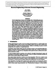
Reverse Engineering for Generation of 3D-Building-Information-Models Applying Random Variables in Computer Aided Design Christian CLEMEN, Frank GIELSDORF and Lothar GRÜNDIG, Germany 1. MOTIVATION There are common problems in reverse engineering for the generation of Building-Models from “original” measurements. It has to be distinguished between ”original” measurements with stochastic character, and ”measurement-function” in CAD-Systems, which is not more than a derived geometry parameter. Problems that occur are for instance: The reference dimension does not fit, different floors do not fit, parts do not adjoin or single measurements are simply forgotten.
Fig. 1 Common problems in reverse engineering for building-models
Those typical errors are not noticed until the building-model is constructed in CAD. Obviously it is essential to collect data and to check the consistency at the same time! Facility-Management-Projects do often fail because there is no geometrical data-base or dataacquisition is too expensive. Within an information-model the building-geometry and the building-topology are the overall basis (framework) of all other data, such as rent, heating costs or lodger. TS 6 – 3D Cadastre 2/8 Christian Clemen, Frank Gielsdorf and Lothar Gründig TS6.5 Reverse Engineering for Generation of 3D-Building-Information-Models Applying Random Variables in Computer Aided Design From Pharaohs to Geoinformatics FIG Working Week 2005 and GSDI-8 Cairo, Egypt April 16-21, 2005
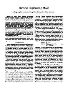
The usability of Building Information System (BIS) increases with the graphical representation of the building structure. Geometrical representation is suitable for human spatial cognition. The graphic representation is calculated from the geometric basic-data. Professional surveyors are too expensive to acquire these basic-data. There is a need for an intelligent software system which makes it possible for layman to acquire building geometry data. So data collection becomes affordable. Laymen are neither used to work with professional CAD-Software nor are they used to handle surveying instruments like total stations. Laymen rather want to sketch a plan than construct a drawing. From the software-developer view “to sketch a room” means to determine the room topology. The “Department of Geodesy and Geoinformation” (University of Technology Berlin) is developing an easy-to-use 3D data collection tool, which enables layman to sketch a roomtopology and to link measurements to this topology. The user is lead by a “traffic light” as shown in Fig. 2. First the user inserts the room topology by sketching the floor plane and upright projections. Secondly he inserts geometrical data, such as measurements and constraints, into the system. The software enables the user to know whether the threedimensional room geometry can be calculated (no data missing) or if it is even possible to verify the measurements (geometry is over-constraint, redundant dimensioning). If the system tells him, that everything is fine (checked) he can leave the room and a data file (XML) containing topology, geometry, constraints and measurements in an appropriate data model (XML Schema) - is stored to disk.
Fig. 2 A traffic light concept for an easy-to-use 3D data-collection tool
Beside the data-collection-tool an analysis-tool is designed and implemented as prototype. It handles data analysis and export-functionality to other CAD/FM Software. This software is designed for professional surveyors. This software “checks in” the above mentioned “room” TS 6 – 3D Cadastre 3/8 Christian Clemen, Frank Gielsdorf and Lothar Gründig TS6.5 Reverse Engineering for Generation of 3D-Building-Information-Models Applying Random Variables in Computer Aided Design From Pharaohs to Geoinformatics FIG Working Week 2005 and GSDI-8 Cairo, Egypt April 16-21, 2005
files, aggregates the single rooms to a building model (room puzzle) by merging the topology and the geometry (topological matching, geometrical transformation) and offers special tools (generalization, level of detail, calculation of areas/volumes, determination of escape routes). The major task for the “analysis tool” is the geodetic adjustment (least-squares-estimation). Furthermore it exports the drawing geometry in several standard files formats (DXF,DWG,VRML). However, geometry does not end in itself. We aim to integrate the possibility to attach application related data (construction physics, structural damage, preservation of ancient monuments, facility management). IFC (Industry Foundation Classes) might be the appropriate data model to export semantic and geometric data.
Fig. 3 Data collection and analysis tool
Why is CAD standard software not suitable for this challenge, neither for a data-collectiontool, nor for the analysis-tool? What is the difference between planning/constructing and reverse engineering? Why is least-square-estimation the appropriate kernel-method for this system? How do geodetic networks differ from building-structure? In the following sections we want to answer these questions by formulating six theses. Therefore we face the challenge of reverse engineering with CAD-Models and typical geodetic applications.
TS 6 – 3D Cadastre 4/8 Christian Clemen, Frank Gielsdorf and Lothar Gründig TS6.5 Reverse Engineering for Generation of 3D-Building-Information-Models Applying Random Variables in Computer Aided Design From Pharaohs to Geoinformatics FIG Working Week 2005 and GSDI-8 Cairo, Egypt April 16-21, 2005
2. CAD VS. SURVEYING CAD Systems are devised to support a planning and construction process. The user already “knows” the geometry of the building. While inserting new geometric entities (point, line, polygon) he continually checks if the drawing matches his brainchild. The system takes the geometric value “as it is”. In the process of reverse-engineering the surveyor does not “know” the real object (building). Measuring is the only access to the “real world” that the user wants to represent in a geometry model. In geodetic surveying measurement values are seen as random variables, due to the blur of human perception and technical deficiency. Thesis 1: In CAD geometry-input is deterministic while “real” measuring-input should be modeled as random variable. How does a surveyor handle the problem, that measurement values are blurred or maybe totally wrong? More measurement values than actually needed are used to compute the geometry. The geometry is over-constraint, redundant observations are used. Only with redundant observations the computed geometry can be distinguished as reliable. Common CAD systems do not handle over-constrained models with redundant observations. Thesis 2: CAD is not suitable for reliable measurement evaluation, due to the need for redundant measurement values. In cadastral-information-systems (land registration) maps are seen as the representation of the absolute geometry, which can be calculated out of measurements (relative geometry). In the German Cadastre the legally binding entity is the original measurement value, not the absolute geometry. Why should this concept be introduced to BIS? Because the measurement values are stochastically independent, whereas the absolute geometry-parameters are a function of the measurement values. The practical use of this approach is that one is able to improve or update the geometry model step by step without discard the original data. Furthermore error detection is much simpler if the original measurement values are handled as primary data. Thesis 3: CAD uses the absolute geometry as primary data, whereas surveyors use therefore the relative geometry (measurements) . The way to determine the absolute geometry from a given relative geometry is statistical adjustment. This least-squares-estimation algorithm succeeds if there are not too many unknowns to determine. The problem is, that “build-in” geometry-models of CAD-Systems (ex. ACIS in AutoCAD) describe the absolute geometry highly-redundant. This is because most models refer the building-topology to the building-geometry via the Vertex-Point reference. Sometimes (ex. DXF) even points at the same place are instantiated several times. As shown in [1] it is much better to link the geometry to the topology via a Face/MeshSurface reference in order to apply statistical adjustment to CAD. TS 6 – 3D Cadastre 5/8 Christian Clemen, Frank Gielsdorf and Lothar Gründig TS6.5 Reverse Engineering for Generation of 3D-Building-Information-Models Applying Random Variables in Computer Aided Design From Pharaohs to Geoinformatics FIG Working Week 2005 and GSDI-8 Cairo, Egypt April 16-21, 2005
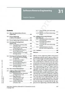
Thesis 4: Highly redundant absolute geometry-representation in CAD makes adjustment application impossible. 3. BUILDING INFORMATION MODELS VS. GEODETIC NETWORKS MODELS So far, we have shown the deficiency of CAD concerning to measurement evaluation. But why can’t we use geodetic standard software for data-collection and data-analysis in Building Information Systems? In both domains there are 3D-Models, so the difference is not the geometric dimension. However, geodesists are used to represent objects by significant points, which leads to a comparative simple “object-topology”. The observation-topology, implied by measurements or local coordinate systems might be complex, but the object-topology is significantly different to an object-topology as shown in fig Fig. 4 A topological space is a set X with a collection t of subsets such that t is a topology on X. In geodetic applications the topological space (XG,tG) is given by a set XG of (3D) points, and the topology tG is given by the observations. This is what we call “observation-topology”. In CAD there is no “observation-topology” but an “object-topology”. Object means in this case the building. The topological space (XCAD , tCAD) is given by a set XCAD of (3D) points, and the topology tCAD is given by the edges. This is the simplest case of a wire-frame model. Actually the building structure is expressed with a cell-complex, containing several topological subsets like nodes, edges, faces or rooms.
Fig. 4 Object Topology vs. Observation Topology
Thesis 5: Geodetic software is not suitable for reverse-engineering of buildings because it does not model the object topology.
TS 6 – 3D Cadastre 6/8 Christian Clemen, Frank Gielsdorf and Lothar Gründig TS6.5 Reverse Engineering for Generation of 3D-Building-Information-Models Applying Random Variables in Computer Aided Design From Pharaohs to Geoinformatics FIG Working Week 2005 and GSDI-8 Cairo, Egypt April 16-21, 2005
We introduced observation types like “point in plane”, “parallel distance of two meshes” or “angle edge-mesh” to the model. These observations (geometric constraints) refer the object topology. So object-topology is an essential part of the a 3D building data model. The geometry is not necessarily expressed with significant points but also with curves, planes or quadrics. In geodetic applications the geometry is mostly described with significant points. Thesis 6: Geodetic software is not suitable for reverse-engineering of buildings because it assumes a discrete point representation. 4. OUTLOOK: LEAST-SQUARES-ESTIMATION IN CAD-SYSTEMS By integrating Least-Squares-Estimation into a CAD-Environment the user benefits from both approaches. The CAD handles the object topology and the consistent geometry, while an adjustment module handles redundant observations and geometric constraints. The role of Least-Squares-Estimation is mapping relative redundant measurements to the most likely consistent geometry.
Fig. 5 UML-Sequence: Interaction GUI, Adjustment and 3D-Modeler
For instance AutoCAD could be used for the graphical user interface and ACIS [2] as 3DGeoemty-modeler. ACIS offers a powerful geometry/topology API. The ObjectARX library TS 6 – 3D Cadastre 7/8 Christian Clemen, Frank Gielsdorf and Lothar Gründig TS6.5 Reverse Engineering for Generation of 3D-Building-Information-Models Applying Random Variables in Computer Aided Design From Pharaohs to Geoinformatics FIG Working Week 2005 and GSDI-8 Cairo, Egypt April 16-21, 2005
(AutoDesk) could be used for the communication between the GUI, Adjustment tool and the 3D-Modeler. How theses modules interact is shown in Fig. 5 Furthermore our experiences had shown, that stochastically modeled observations are essentially needed for the measurement evaluation of redundant measurements. The IFC datamodel contains the capability to express geometric constraints (IfcContraint, IfcMetric). So far there is just a enum-type (IfcConstraintEnum) to express the quality of a constraint. For geodetic applications a standard deviation data type should be introduced to the ifc-datamodel. REFERENCES [1]
[2] [3]
Gründig, L., Gielsdorf, F.: "Geometrical Modeling for Facility Managment Systems Applying Surface Parameter", XXII FIG Federation Internationale des Geometres Congress, Washington D.C., USA www.spatial.com www.iai-international.org
BIOGRAPHICAL NOTES Christian Clemen, born 1976. Graduated in 2004 as Dipl.-Ing. in Surveying from Technical University of Berlin. Since 2004 Assistant at the Department of Geodesy and Geoinformation, Technical University of Berlin. Dr. Frank Gielsdorf, born 1960. Graduated in 1987 as Dipl.-Ing. in Surveying from Technical University of Dresden. Obtaining doctoral degree in 1997 from Technical University of Berlin. Since 1995 Assistant Professor at the Department of Geodesy and Geoinformation, Technical University of Berlin. Prof. Dr. Lothar Gründig, born in 1944. Graduated in 1970 as Dipl.-Ing. in Surveying and obtaining doctoral degree in 1975, both from University of Stuttgart. Since 1988 Professor of Geodesy and Adjustment Techniques at the Department of Geodesy and Geoinformation, Technical University of Berlin. CONTACTS Prof. Dr.-Ing. Lothar Gründig Technische Universität Berlin Fachgebiet für Geodäsie und Ausgleichungsrechnung Sekretariat H20 Straße des 17. Juni 135 D-10623 Berlin GERMANY Tel. +49 (0)30 314-22375 Fax +49 (0)30 314-21119 Email:
[email protected] Web site: www.survey.tu-berlin.de TS 6 – 3D Cadastre 8/8 Christian Clemen, Frank Gielsdorf and Lothar Gründig TS6.5 Reverse Engineering for Generation of 3D-Building-Information-Models Applying Random Variables in Computer Aided Design From Pharaohs to Geoinformatics FIG Working Week 2005 and GSDI-8 Cairo, Egypt April 16-21, 2005