Hindawi Publishing Corporation ISRN Electronics Volume 2013, Article ID 850267, 9 pages http://dx.doi.org/10.1155/2013/850267
Research Article Reversible Logic-Based Fault-Tolerant Nanocircuits in QCA Bibhash Sen,1 Siddhant Ganeriwal,1 and Biplab K. Sikdar2 1 2
Department of Computer Science and Engineering, National Institute of Technology, Durgapur 713209, India Department of Computer Science and Technology, Bengal Engineering and Science University, Shibpur 711103, India
Correspondence should be addressed to Bibhash Sen;
[email protected] Received 28 April 2013; Accepted 26 May 2013 Academic Editors: D. Rossi and P. Wachulak Copyright © 2013 Bibhash Sen et al. This is an open access article distributed under the Creative Commons Attribution License, which permits unrestricted use, distribution, and reproduction in any medium, provided the original work is properly cited. Parity-preserving reversible circuits are gaining importance for the development of fault-tolerant systems in nanotechnology. On the other hand, Quantum-dot Cellular Automata (QCA), a potential alternative to CMOS, promises efficient digital design at nanoscale. This work targets design of reversible ALU (arithmetic logic unit) in QCA (Quantum-dot Cellular Automata) framework. The design is based on the fault tolerant reversible adders (FTRA) introduced in this paper. The proposed fault tolerant adder is a parity-preserving gate, and QCA implementation of FTRA achieved 47.38% fault-free output in the presence of all possible single missing/additional cell defects. The proposed designs are verified and evaluated over the existing ALU designs and found to be more efficient in terms of design complexity and quantum cost.
1. Introduction Reversible logic has attractive perspective of constructing digital devices that can realize computing unit with almost zero power dissipation. Landauer [1] proved that for irreversible computations, each bit of information loss generates 𝑘𝐵 𝑇𝑙𝑛2 joules of heat energy. The energy 𝐸bit required for a binary transition is given by SNL (Shannon-Von NeumannLandauer) expression in [1] as follows: 𝐸bit ≥ 𝐸SNL = 𝑘𝐵 𝑇𝑙𝑛2 = 0.017 eV,
(1)
where 𝑘𝐵 is Boltzmann constant and 𝑇 = 300 K. This is the minimum energy to process a bit. Bennett [2] showed that a zero power dissipation in logic circuit is possible only if the circuit is composed of reversible logic gates. Since QCA circuits are clocked information preserving systems, the energy dissipation of QCA circuits can be significantly lower than 𝑘𝐵 𝑇𝑙𝑛2. This feature favours the introduction of QCA technology in reversible logic design. Though, reversibility recovers bit loss, but it is not able to detect bit error in circuit. Fault-tolerant reversible circuits are capable of preventing errors at outputs. If the system itself made of fault-tolerant components, then the detection and correction of faults become easier and simple. In communication and many other systems, fault tolerance is achieved by
parity. Therefore, parity-preserving reversible circuits will be the future design trends to the development of fault-tolerant reversible systems in nanotechnology. On the other hand, QCA (Quantum-dot Cellular Automata) is considered to be promising in the field of nanotechnology due to their extremely small sizes and ultralow-power consumption [3]. The QCA is based on encoding binary information in the charge configuration of quantum-dot cells. The interaction between cells is coulombic and provides the necessary computing power. The fundamental unit of QCAbased design is the 3-input majority gate [3]. Majority gate with inverter, called MI, is used to realize the QCA designs because of its functional incompleteness. Significant contributions have been made in the literature towards the design of arithmetic units in [4–6]. Also, faulttolerant full adder circuits are explored in [7–10]. However, there have only been a few efforts towards designing reversible fault-tolerant ALUs. This motivates us to design a fault-tolerant reversible ALU architecture considering QCA technology. A cost-effective realization of a fault-tolerant reversible adder (FTRA) is first introduced. It is then utilized to synthesize the desired faulttolerant reversible arithmetic logic unit which outperforms the efficiency of existing designs in terms of design complexity and quantum cost. The major contributions of this work
2
ISRN Electronics
around reversible QCA architecture can be summarized as follows: (i) realization of generic fault-tolerant reversible adder having parity-preserving logic with cost effective quantum cost; (ii) the presented fault-tolerant reversible adder block is used to realize different arithmetic circuit such as full adder, subtractor, ripple carry adder, and carry-skip logic; (iii) synthesis of a fault-tolerant reversible arithmetic logic unit (ALU) using proposed adder; (iv) application of the proposed adder in QCA nanotechnology with effective fault tolerance of 47.38% in the presence of all possible single missing/additional cell defects. Simulations using QCADesigner [11] supports all the results presented.
2. Preliminaries Reversible Logic. A logic gate is reversible if the mapping of its inputs to outputs is bijective; that is, every distinct input yields a distinct output, and the number of inputs is equal to the number of outputs [12]. An important cost metrics in reversible logic circuits is the quantum cost. The cost of every 2 × 2 gate is the same; that is, unity and the cost of 1 × 1 gate are zero [13]. Any reversible logic can be realized using primitive quantum gates, like 1 × 1 NOT gates and 2 × 2 reversible gates, such as Controlled-𝑉, Controlled-𝑉+ , and CNOT gate (Figure 1). The quantum cost of a reversible gate can be calculated by counting the numbers of primitive quantum gates used in implementing it. The fan-outs and feedback paths are not permitted in reversible logic. QCA Basics. A QCA cell consists of four quantum dots positioned at the corners of a square (Figure 2(a)) and contains two free electrons [3]. The electrons can quantum mechanically tunnel among the dots and settle either in polarization P = −1 (logic 0) or in P = +1 (logic 1) as shown in Figure 2(b). Timing in QCA is accomplished by the cascaded clocking of four distinct and periodic phases [3]. The basic structure realized with QCA is the 3-input majority gate, MV (A, B, C) = Maj (A, B, C) = AB + BC + CA (Figure 2(c)). It can also function as a 2-input AND (2-input OR) logic by fixing one of the three input cells to P = −1 (P = +1). Inverter is realized in two different orientations as shown in Figure 2(d). In QCA-based logic implementations, two kinds of wire crossover, termed coplanar crossover and multilayer crossover, are possible. Figure 2(e) describes the coplaner wire crossing considering a 90∘ (×-cell) and a 45∘ (+-cell) structures. Fault-Tolerant Logic. Fault tolerance enables a system to operate properly in the event of the failure of some its components. If the system itself is made up of fault-tolerant components, then the detection and correction of faults become easier and simple. A fault-tolerant (FT) reversible gate is also called
Table 1: Truth table of proposed fault-tolerant adder. A 0 0 0 0 0 0 0 0 0 0 0 0 0 0 0 0 1 1 1 1 1 1 1 1 1 1 1 1 1 1 1 1
B 0 0 0 0 0 0 0 0 1 1 1 1 1 1 1 1 0 0 0 0 0 0 0 0 1 1 1 1 1 1 1 1
C 0 0 0 0 1 1 1 1 0 0 0 0 1 1 1 1 0 0 0 0 1 1 1 1 0 0 0 0 1 1 1 1
D 0 0 1 1 0 0 1 1 0 0 1 1 0 0 1 1 0 0 1 1 0 0 1 1 0 0 1 1 0 0 1 1
E 0 1 0 1 0 1 0 1 0 1 0 1 0 1 0 1 0 1 0 1 0 1 0 1 0 1 0 1 0 1 0 1
P 0 0 0 0 0 0 0 0 0 0 0 0 0 0 0 0 1 1 1 1 1 1 1 1 1 1 1 1 1 1 1 1
Q 0 0 0 0 0 0 0 0 1 1 1 1 1 1 1 1 0 0 0 0 0 0 0 0 1 1 1 1 1 1 1 1
R 0 0 1 1 1 1 0 0 1 1 0 0 0 0 1 1 1 1 0 0 0 0 1 1 0 0 1 1 1 1 0 0
S 0 0 1 1 0 0 1 1 0 0 0 0 1 1 1 1 0 0 0 0 1 1 1 1 1 1 0 0 1 1 0 0
T 0 1 1 0 0 1 1 0 1 0 1 0 0 1 0 1 0 1 0 1 1 0 1 0 0 1 1 0 0 1 1 0
conservative gate [7]. The hamming weight of its inputs and outputs is equal. Let the input and output vectors of any faulttolerant gate be 𝐼V = 𝐼0 , 𝐼1 , . . . , 𝐼𝑛−1 and 𝑂V = 𝑂0 , 𝑂1 , . . . , 𝑂𝑛−1 , where (i) 𝐼V ⟨Bijective⟩𝑂V , (ii) 𝐼0 ⊕ 𝐼1 ⊕ ⋅ ⋅ ⋅ ⊕ 𝐼𝑛−1 = 𝑂0 ⊕ 𝑂1 ⊕ ⋅ ⋅ ⋅ ⊕ 𝑂𝑛−1 . Few fault-tolerant reversible 3 × 3 gate-like Feynman double gate (F2G), Fredkin (FRG), NFT, and so forth and 4 × 4 gate like MIG are already investigated.
3. Related Work In [14], the feasibility of the parity-preserving approach to design of reversible logic circuits was explored. Few new fault-tolerant reversible logic gates were proposed in [8]. Fault-tolerant full adder circuits are explored in [7–10]. In all these researches, no such single logic unit was identified to implement fault-tolerant full adder. Also, the fault tolerance
ISRN Electronics
3 A
A A A
⊕
A
A
A
A A⊕B
⊕
B
(a)
B
If (A) then V(B) else B
V
(b)
B
If ( A) then V+ (B) else B
V+
(c)
(d)
Figure 1: Elementary quantum logic gates: (a) NOT, (b) exclusive OR, (c) square root of NOT (SRN), and (d) Hermitian matrix of SRN. Localised electron Tunnelling potential
Quantum well
Junction tunnel
P = −1
P = +1
Binary “0” binary “1”
(a) Structure of a QCA Cell
(b) QCA cell with two different polarizations
A B “+” cell
B
F
A
A
Input
Output
A
A “×” cell
A
C (c) Majority voter
A
B
(d) Inverter
(e) Wire crossing
Figure 2: QCA basics.
capability of those logic gates was not explored quantitatively. Significant contributions have been made in the literature towards the design of arithmetic units in [4–6]. However, there have only been a few efforts towards designing reversible fault-tolerant ALUs. A new fault-tolerant method based on majority multiplexing (Maj-MUX) is proposed for QCA in [15]. But the application of reversible logic in QCA to achieve fault tolerance was not identified (which is of primary interest to us in this work).
4. Proposed Fault-Tolerant Adder In communication and many other systems, fault tolerance is achieved by parity. A parity-preserving reversible gate, when used with an arbitrary synthesis strategy for reversible logic circuits, allows any fault that affects no more than a single logic signal to be detectable at the circuit’s primary outputs [14]. In [10], a minimum number of garbage outputs and constant inputs for a fault-tolerant reversible full adder circuit are specified as 3 and 2. Keeping in mind to have minimum number of garbage outputs and constant inputs, a new fault-tolerant reversible adder (FTRA) is proposed here (Figure 3(a)) followed by design of different adder-based circuits. The input to output mapping of FTRA structure is P = A, Q = A⊕B, R = A⊕B⊕C⊕D, S = (A⊕B)(C⊕D)(AB⊕D),
and T = (A ⊕ B)(C ⊕ D)(AB ⊕ D) ⊕ E, where A, B, C, D, and E are inputs and P, Q, R, S, and T are outputs. It is a 5 × 5 reversible gate with a quantum cost of 8 (Figure 3(b)). The proposed reversible FTRA gate is parity preserving. The reversibility and parity preserve nature of the proposed FTRA gate can be verified from Table 1. A fault-tolerant reversible full adder and subtractor circuit using the newly proposed FTRA gate is shown in Figure 4(a). The design uses only one FTRA gate, has a quantum cost of 8, produces 3 garbage outputs, and uses 2 constant inputs only. No such single logic gate is found which can implement a fault-tolerant reversible full adder with such quantum cost and less complexity. Design capability of the proposed adder is further analyzed by implementing a 4bit fault-tolerant ripple carry adder (Figure 4(b)) and carry skip adder (Figure 4(c)). A comparative performance analysis of the proposed design with existing designs is reported in Table 2 with enviable gate count besides other parameters. The results shows that the proposed design is much more effective than the existing designs. The advantage of our method is in the implementation of this logic at gate level. Thus, once the required gates have been designed and an appropriate synthesis framework has been established, fault-tolerant implementation requires no extra expenditure in design or verification effort.
4
ISRN Electronics
A
P=A
B
Q= A⊕B
C
R= A⊕B⊕C⊕D
FTRA
D
S = (A ⊕ B)(C ⊕ D) ⊕ (AB ⊕ D)
E
T = (A ⊕ B)(C ⊕ D) ⊕ (A B ⊕ D) ⊕ E
(a) Block diagram fault-tolerant adder
P=A
A
C
Q= A⊕B
⊕
B
R= A⊕B⊕C⊕D
⊕
⊕ V
D
V
+
S = (A ⊕ B)(C ⊕ D) ⊕ (AB ⊕ D)
V
V
⊕
⊕
E
T = (A ⊕ B)(C ⊕ D) ⊕ (A B ⊕ D) ⊕ E
(b) Quantum implementation of fault-tolerant adder
Figure 3: Proposed fault-tolerant reversible adder.
A
G
C
G
B
G Sum
B
G
C 0 0
FTRA
Cout
G
A 0 0
Full adder
Diff
FTRA
Bout G
Full subtractor
(a) Fault-tolerant full adder and subtractor A0 B0 Cin 0 0
FTRA
G A1 G B1
FTRA
0
G A2 G B2 0
G A3 G B3
FTRA
0
S1
S0
G G FTRA
Cout G
S2
S3
(b) Fault-tolerant ripple carry adder A0 B0
0 0
G A2 B2
G A1 B1 FTRA
0 S0
FTRA
0
G A3 B3 FTRA
0
S1
G FTRA G
S2
S3
Cin 0 0
0
0
F2G
FRG
FRG
G
GG
GG 0 FRG
GG
FRG
G G Cout
(c) Fault-tolerant carry-skip adder
Figure 4: Implementation of different logic circuit with proposed FTRA.
ISRN Electronics
5 G G
Cin
0
B 0 0
FTRA
Cout / Bout
C0
F2G
G
C2
F2G
C0 A
F2G
0
C1
FRG
F2G
FRG
C2 G Output
C1 G
Figure 5: Fault-tolerant ALU with proposed FTRA.
Bn 0 0
0
F2G
An
B1 0 0
F2G
0
0
F2G
A1
F2G
0
G G Cout / Bout
FTRA
FRG
FTRA
F2G
0
F2G C0
A0
F2G
0
C0
G FRG
C2 G
FRG
G
FRG
G
C1 G
Outn
G G F2G
F2G
FRG
G Out1
G
G G
Cin
B0 0 0
F2G
FTRA
F2G G C2
FRG
C1
F2G
Out0
G
Figure 6: Implementation of n-bit fault-tolerant ALU. Table 2: Performance analysis of different fault-tolerant full adders. Parameter Gate count Quantum cost Garbage outputs Constant inputs Logical calculations
[7] 5 25 4 2 8𝛼 + 16𝛽 + 8𝛿
[8] 6 18 6 5 12𝛼 + 8𝛽 + 4𝛿
𝛼: “two-input EXOR calculation”; 𝛽: “two-input AND calculation”; 𝛿: “NOT calculation.”
[9] 2 14 3 2 8𝛼 + 6𝛽 + 2𝛿
[10] 4 11 3 2 9𝛼 + 4𝛽 + 3𝛿
Proposed 1 8 3 2 13𝛼 + 4𝛽 + 𝛿
6
ISRN Electronics A
P
B
Q
−1
−1 −1
−1 −1
−1
−1
R −1
−1 −1
−1 −1 −1
−1
−1
S −1
−1 −1 −1 −1 −1
−1 −1
−1
T −1
−1 −1
E
C D 0123 Clocking zone
Figure 7: QCA implementation of fault-tolerant adder.
5. FTRA Gates in QCA Computing
Table 3: Different function of ALU. C0 0 0 0 0 1 1
C1 0 0 1 1 X X
C2 0 1 0 1 0 1
Output AB A+B AB A+B A⊕B⊕C A⊕B⊕C
Function AND NOR NAND OR ADD SUB
4.1. Design of Fault-Tolerant Arithmetic Logic Unit (ALU). The reversible fault-tolerant 1-bit ALU is designed with one FTRA gate, two Fredkin gates, and four Double-Feynman gates. Thus the design uses a total of 7 gates and has a quantum cost of 26 (Figure 5). It produces 5 garbage outputs and uses 4 constant inputs. The various operations performed by the proposed FTRA-ALU is shown in Table 3. The total logical operations performed is 21𝛼 + 10𝛽 + 5𝛿. The main advantage of the proposed ALU logic is its programmable feature; that is, just programming the constants C1, C2, and C3, different ALU functions are implemented. Besides its fault tolerance, this programmable feature adds more flexibility in reversible ALU. Figure 6 shows the design of an n-bit fault-tolerant ALU which is synthesized by cascading the 1-bit ALU module explored in Figure 5.
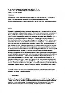
To demonstrate the application of the proposed fault-tolerant design approach to reversible adder in emerging nano-technologies, Quantum-dot cellular automata (QCA) technology is considered because reversible logic has potential applications in QCA computing. The QCA implementation of the proposed FTRA gate is shown in Figure 7. The design requires 27 MVs and has a delay of 12 clock zones. In the following section, the fault tolerance capability is established quantitatively. FTRA simulation shown in Figure 8 is performed by fixing D and E to 0. In this simulation result, R generates sum, and S propagates carry.
6. Fault Tolerance of Proposed Logic Gate In QCA manufacturing, defects can occur during the synthesis and deposition phases, although defects are most likely to take place during the deposition phase [16]. Researchers have shown that QCA cells are more susceptible to missing and additional QCA cell defects [17]. In additional cell defect, an additional cell is deposited on the substrate. The missing cell defect occurs due to the missing of a particular cell. Researchers have been addressing the design and test of QCA circuits assuming the single missing/additional cell defect model.
ISRN Electronics
7 Max: 1.00e + 000 A Min: −1.00e + 000 Max: 1.00e + 000 B Min: −1.00e + 000 Max: 1.00e + 000 C Min: −1.00e + 000
1
0
1
0
Max: 9.54e + 000 1 P Min: −9.54e + 000
1
0
1
1
0
1
0
1
0
1 1
Max: 9.54e + 000 R Min: −9.54e + 000
0
0
0
0
1
0
0
0
0
1
1
0
0
1
Max: 9.54e + 000 Q Min: −9.54e + 000
Max: 9.54e + 000 S Min: −9.54e + 000
0
1
0
1
1
0
1
0
0
1
0
Max: 9.54e + 000 T Min: −9.54e + 000
Figure 8: Simulation result of fault-tolerant QCA adder.
A FO1
P Q
B INV1
FO5 −1 FO2
FO3
INV4
CW1
LS14
INV2
INV3
MAJ1
LS20
LS19
FO8 MAJ2
−1 −1 MAJ15 INV15 INV16 FO16
MAJ3
FO14
CW2
LS1
FO6
LS2
LS4
INV7
−1
MAJ4
CW4
INV5
CW3
LS3
FO15
1
−1
MAJ5
FO9
MAJ6
LS5 INV6
MAJ6
CW8
INV18
−1
MAJ16
FO17 −1
MAJ7
LS15
1
LS16
LS21
INV17 INV19
MAJ17
−1
LS22
−1 LS23
LS24
CW9
LS25
FO18
INV20
CW12
INV21
INV22 MAJ20
−1
−1
MAJ19
MAJ21
S
FO19
R
CW11
MAJ18
LS16 1
FO7 −1 FO4
FO10
INV9
MAJ8
CW5
INV10 INV11 MAJ10
−1
MAJ11
LS17
LS8
INV8
−1 FO11
LS11
LS9
LS7
MAJ9 LS10
INV12 CW6 FO12 −1
FO13
CW7
C
D
1
LS18
FO20 CW10 CW13 −1
LS12 INV13 INV14 MAJ13 MAJ12 LS13
MAJ14
−1
LS28 LS27
INV23
LS30
INV24 INV25 MAJ23 MAJ22
−1
MAJ24
LS31
INV26
CW14
INV27
−1
MAJ25
LS29 1
1
FO21 LS34
E
Figure 9: HDLQ modelling of QCA-based fault-tolerant adder.
LS33
LS32 INV28
MAJ26
−1
MAJ27
T
1
8
ISRN Electronics Table 4: Fault pattern of proposed fault-tolerant adder.
Input 𝑎0 𝑎1 𝑎2 𝑎3 𝑎4 𝑎5 𝑎6 .. . 𝑎30 𝑎31
Output 𝑎0 𝑎1 𝑎7 𝑎6 𝑎4 𝑎5 𝑎3 .. . 𝑎17 𝑎16
1 𝑎16 𝑎17 𝑎23 𝑎22 𝑎20 𝑎21 𝑎19 .. . 𝑎13 𝑎12
2 𝑎12 𝑎13 𝑎8 𝑎8 𝑎11 𝑎10 𝑎15 .. . 𝑎17 𝑎16
3 𝑎0 𝑎1 𝑎7 𝑎7 𝑎4 𝑎5 𝑎3 .. . 𝑎19 𝑎18
Fault pattern ⋅⋅⋅ 43 44 45 ⋅⋅⋅ 𝑎2 𝑎1 𝑎0 ⋅⋅⋅ 𝑎3 𝑎0 𝑎1 ⋅⋅⋅ 𝑎5 𝑎6 𝑎7 ⋅⋅⋅ 𝑎4 𝑎7 𝑎6 ⋅⋅⋅ 𝑎6 𝑎5 𝑎4 ⋅⋅⋅ 𝑎7 𝑎4 𝑎5 ⋅⋅⋅ 𝑎1 𝑎2 𝑎3 .. .. .. .. . . . . ⋅⋅⋅ 𝑎19 𝑎16 𝑎17 ⋅⋅⋅ 𝑎18 𝑎17 𝑎16 Average FT = fault tolerance
In the proposed work, the QCA layout of the FTRA gate is converted into the corresponding hardware description language notations using the HDLQ Verilog library [18]. The HDLQ design tool, Verilog equivalent for QCA, consists of a Verilog HDL library of QCA devices, that is, MV, INV, FO, Crosswire (CW), and L-shape wire with fault injection capability. The HDLQ-modeled design of the FTRA gate is shown in Figure 9, and an exhaustive testing of the HDLQ model of the FTRA gate is conducted with 32 input patterns in the presence of all possible single missing/additional cell defects. The design is simulated using the Verilog HDL simulator in the presence of faults to determine the corresponding outputs. Testing of the FTRA gate generated 78 unique fault patterns at the output, as shown in Table 4. Due to huge volume of data, the fault pattern table is partially shown. In the fault patterns study shown in the Table 4, 𝑎𝑖 is the five-bit pattern with an equivalent decimal value of 𝑖. For example, 𝑎0 represents 00000 (decimal 0), and 𝑎31 represents 11111 (decimal 31). In Table 4, first two columns present the correct behaviour of FTRA gate, that is, for a particular input vector corresponding expected output vector. Each row of the Table 4 represents the output generated after the fault injection of different 78 modules of the HDLQ model (Figure 9), for example, for given input 𝑎0 , after the fault injection of different modules, the generated fault pattern is 𝑎0 , 𝑎16 , 𝑎12 , . . . , 𝑎1 , 𝑎0 . From those fault patterns, we observed that there are average 47.38% successful patterns that produce the correct output, even when there is a fault.
7. Conclusions This work presents a novel architecture of fault-tolerant reversible adder (FTRA) gate. Experimental results establish the fact that the proposed FTRA achieved significant improvements in reversible circuits over the existing ones. A reversible arithmetic logic unit is synthesized based on the FTRA proposed. This is first attempt to synthesize a fault-tolerant full adder/subtractor using only single reversible logic block (FTRA) with optimal quantum cost to avoid wire-crossing bottleneck. Also, the application of this
⋅⋅⋅ ⋅⋅⋅ ⋅⋅⋅ ⋅⋅⋅ ⋅⋅⋅ ⋅⋅⋅ ⋅⋅⋅ ⋅⋅⋅ .. . ⋅⋅⋅ ⋅⋅⋅
76 𝑎12 𝑎1 𝑎7 𝑎6 𝑎5 𝑎5 𝑎3 .. . 𝑎17 𝑎16
77 𝑎1 𝑎0 𝑎6 𝑎6 𝑎4 𝑎5 𝑎2 .. . 𝑎16 𝑎16
78 𝑎0 𝑎0 𝑎7 𝑎6 𝑎4 𝑎5 𝑎3 .. . 𝑎17 𝑎16
Success rate
FT%
32/78 34/78 38/78 38/78 37/78 39/78 40/78 .. . 41/78 42/78
41.02 43.59 48.72 48.72 47.43 50.00 51.28 .. . 52.56 53.78 47.38
fault-tolerant logic in QCA nanotechnology gets an extra advantage in fault-tolerant computing with effective 47.38% fault-free output in the presence of all possible single missing/additional cell defects. Though, the clocking structure beneath the QCA cell layer is also very important and nontrivial research issue.
Acknowledgment The authors would like to thank Mr. Samik Some, UG student of CSE department, NIT Durgapur, for his valuable help in testing the design using HDLQ tool.
References [1] R. Landauer, “Irreversibility and heat generation in the computing process,” IBM Journal of Research and Development, vol. 5, no. 3, pp. 183–191, 1961. [2] C. H. Bennett, “Logical reversibility of computation,” IBM Journal of Research and Development, vol. 17, no. 6, pp. 525–532, 1973. [3] C. S. Lent, P. D. Tougaw, W. Porod, and G. H. Bernstein, “Quantum cellular automata,” Nanotechnology, vol. 4, no. 1, pp. 49–57, 1993. [4] Z. Guan, W. Li, W. Ding, Y. Hang, and L. Ni, “An arithmetic logic unit design based on reversible logic gates,” in Proceedings of the 13th IEEE Pacific Rim Conference on Communications, Computers and Signal Processing (PacRim ’11), pp. 925–931, August 2011. [5] M. Morrison and N. Ranganathan, “Design of a reversible ALU based on novel programmable reversible logic gate structures,” in Proceedings of IEEE Computer Society Annual Symposium on VLSI (ISVLSI ’11), pp. 126–131, Washington, DC, USA, July 2011. [6] Y. Syamala and A. V. N. Tilak, “Reversible arithmetic logic unit,” in Proceedings of the 3rd International Conference on Electronics Computer Technology (ICECT ’11), pp. 207–211, April 2011. [7] J. W. Bruce, M. A. Thornton, L. Shivakumaraiah, P. S. Kokate, and X. Li, “Efficient adder circuits based on a conservative reversible logic gate,” in Proceedings of IEEE Symposium on VLSI, pp. 83–88, Washington, DC, USA, 2002. [8] M. Haghparast and K. Navi, “A novel fault tolerant reversible gate for nanotechnology based systems,” American Journal of Applied Sciences, vol. 5, no. 5, pp. 519–523, 2008.
ISRN Electronics [9] Md. S. Islam, M. M. Rahman, Z. Begum, and M. Z. Hafiz, “Efficient approaches for designing fault tolerant reversible carry look-ahead and carry-skip adders,” MASAUM Journal of Basic and Applied Sciences, vol. 1, no. 3, pp. 354–360, 2009. [10] S. K. Mitra and A. R. Chowdhury, “Minimum cost fault tolerant adder circuits in reversible logic synthesis,” in Proceedings of the 25th International Conference on VLSI Design (VLSID ’12), pp. 334–339, January 2012. [11] K. Walus, T. J. Dysart, G. A. Jullien, and R. A. Budiman, “QCADesigner: a rapid design and simulation tool for quantum-dot cellular automata,” IEEE Transactions on Nanotechnology, vol. 3, no. 1, pp. 26–31, 2004. [12] T. Toffoli, “Reversible computing,” in Proceedings of the 7th Colloquium on Automata, Languages and Programming, pp. 632–644, Springer, London, UK, 1980. [13] M. Perkowski, M. Lukac, P. Kerntopf et al., “A hierarchical approach to computer-aided design of quantum circuits,” in Proceedings of the 6th International Symposium on Representations and Methodology of Future Computing Technology, pp. 201– 209, 2003. [14] B. Parhami, “Fault-tolerant reversible circuits,” in Proceedings of the 40th Asilomar Conference on Signals, Systems, and Computers (ACSSC ’06), pp. 1726–1729, November 2006. [15] X. Ma and F. Lombardi, “Fault tolerant schemes for QCA systems,” in Proceedings of the 23rd IEEE International Symposium on Defect and Fault Tolerance in VLSI Systems (DFT ’08), pp. 236–244, October 2008. [16] M. B. Tahoori, J. Huang, M. Momenzadeh, and F. Lombardi, “Testing of quantum cellular automata,” IEEE Transactions on Nanotechnology, vol. 3, no. 4, pp. 432–442, 2004. [17] M. Momenzadeh, M. Ottavi, and F. Lombardi, “Modeling QCA defects at molecular-level in combinational circuits,” in Proceedings of the 20th IEEE International Symposium on Defect and Fault Tolerance in VLSI Systems (DFT ’05), pp. 208–216, October 2005. [18] M. Ottavi, L. Schiano, F. Lombardi, and D. Tougaw, “HDLQ: a HDL environment for QCA design,” Journal on Emerging Technologies in Computing Systems, vol. 2, no. 4, pp. 243–261, 2006.
9
International Journal of
Rotating Machinery
The Scientific World Journal Hindawi Publishing Corporation http://www.hindawi.com
Volume 2014
Engineering Journal of
Hindawi Publishing Corporation http://www.hindawi.com
Volume 2014
Hindawi Publishing Corporation http://www.hindawi.com
Volume 2014
Advances in
Mechanical Engineering
Journal of
Sensors Hindawi Publishing Corporation http://www.hindawi.com
Volume 2014
International Journal of
Distributed Sensor Networks Hindawi Publishing Corporation http://www.hindawi.com
Hindawi Publishing Corporation http://www.hindawi.com
Volume 2014
Advances in
Civil Engineering Hindawi Publishing Corporation http://www.hindawi.com
Volume 2014
Volume 2014
Submit your manuscripts at http://www.hindawi.com
Advances in OptoElectronics
Journal of
Robotics Hindawi Publishing Corporation http://www.hindawi.com
Hindawi Publishing Corporation http://www.hindawi.com
Volume 2014
Volume 2014
VLSI Design
Modelling & Simulation in Engineering
International Journal of
Navigation and Observation
International Journal of
Chemical Engineering Hindawi Publishing Corporation http://www.hindawi.com
Volume 2014
Hindawi Publishing Corporation http://www.hindawi.com
Hindawi Publishing Corporation http://www.hindawi.com
Volume 2014
Hindawi Publishing Corporation http://www.hindawi.com
Advances in
Acoustics and Vibration Volume 2014
Hindawi Publishing Corporation http://www.hindawi.com
Volume 2014
Volume 2014
Journal of
Control Science and Engineering
Active and Passive Electronic Components Hindawi Publishing Corporation http://www.hindawi.com
Volume 2014
International Journal of
Journal of
Antennas and Propagation Hindawi Publishing Corporation http://www.hindawi.com
Shock and Vibration Volume 2014
Hindawi Publishing Corporation http://www.hindawi.com
Volume 2014
Hindawi Publishing Corporation http://www.hindawi.com
Volume 2014
Electrical and Computer Engineering Hindawi Publishing Corporation http://www.hindawi.com
Volume 2014