[3] Altium limited, Altium designer tutorial – getting started with PCB design, ...
add to existing project PCB ... then use finction – „Design/Update PCB document.
RF circuits design Grzegorz Beziuk
Examples of CAE software
References [1] Ansys Incorporation, Ansoft High Frequency Structure Simulator - tutorials, Ansys, (www.ansoft.com) [2] Kraus G., Ansoft designer SV 2.0 – tutorial fo begginers. Open source document, 2005, (http://www.elektronikschule.de/~krausg/) [3] Altium limited, Altium designer tutorial – getting started with PCB design, Altium limited, (http://wiki.altium.com/display/ADOH/Getting+Started+with+Altium+Designer) [4] Altium limited, Denining and running simulation analises, Altium limited, (http://wiki.altium.com/display/ADOH/Getting+Started+with+Altium+Designer)
Introduction Circuit parametrs
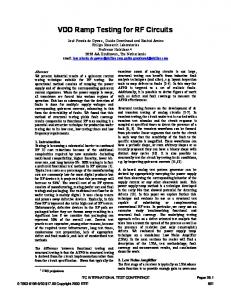
The steps of circuit designing process
Calculations
CAD symulation, PCB designing
Circuit assembly Circuit measurments satisfy parameters?
Circuit optimization no
yes
Circuit fabrication
Introduction Circuits symulation software: Pspice, Orcad, Multisim (free AD), Altium Designer, Tina (free TI), SmartSpice, Hspice, T-Spice, Spectre (RF), Eldo (RF), UltraSim, LT Spice (free LT), NanoSim, Nspice, Hsim, B2Spice, ICAD/4, EDSpice,WINecad, TopSpice, Spice Opus, SiMetrix, Micro-cap Circuits and EM simulation (RF and microwave): Microwave Office (RF), Ansoft Designer (RF), Sonnet Lite (RF, EMC), Agilent ADS
Introduction PCB designing software: Altium Designer (Easytrax, Autotrax, Protel), Eagle,Spectra i Allegro (autorouting), CadStar, Orcad, Tina, Circuit Maker, PCad, PCB Elegance, EDWin, VisualPC, BPECS32, Expert PCB, CirCAD, Layout, McCAD, EPD (RF, hybrid), gEDA (free – linux), ZenitPCB (free), PCB (free), KiCAD (free) Some software contains circuit simulation module and PCB designing modulem, for instance Altium Designer.
Altium designer – circuits symulation Create on your PC folder „....”
Altium designer – circuits symulation
Altium designer – circuits symulation
Altium designer – circuits symulation
Altium designer – circuits symulation
Altium designer – circuits symulation
Altium designer – circuits symulation
Altium designer – circuits symulation
Altium designer – circuits symulation
Altium designer – circuits symulation
Altium designer – circuits symulation
Altium designer – circuits symulation - add power sources VSRC, set up volatge values required for +Ucc, -Uee - add ports (from menu – Vcc power ports) : GND, +Ucc, Uee - add load resistance (R3) - wiring up the circuits - annotate parts - compiling the project
Altium designer – circuits symulation
Altium designer – circuits symulation
Altium designer – circuits symulation
Altium designer – PCB designing - add to existing project PCB - save PCB as „......” - replace in the circuit all sources by appropriate ports, - once again annotate schematic (function – update changings list) - check whether all parts have defined footprints - then use finction – „Design/Update PCB document ***.PcbDoc” - define outline of Pcb (by means of Keep out layer) and set origin
Altium designer – PCB designing
Altium designer – PCB designing
Altium designer – PCB designing
Altium designer – PCB designing
Altium designer – PCB designing
Altium designer – PCB designing - set up all rules - place all components - define new size of Pcb outline - define Pcb clamping points - connect components (one layer board – bottom/top layer, two layers board top and bottom layer)
Altium designer – PCB designing
Altium designer – PCB designing
Altium designer – PCB designing
Altium designer – PCB designing
Ansoft Designer – filter project
Ansoft Designer – filter project
Ansoft Designer – filter project
Ansoft Designer – filter project
Ansoft Designer – filter project
Ansoft Designer – Impedance Matching using a 1 / 4 –Microstrip-Line (on a FR4-Board)
Ansoft Designer – Impedance Matching using a 1 / 4 –Microstrip-Line (on a FR4-Board)
Ansoft Designer – Impedance Matching using a 1 / 4 –Microstrip-Line (on a FR4-Board)
Ansoft Designer – Impedance Matching using a 1 / 4 –Microstrip-Line (on a FR4-Board)
Ansoft Designer – Impedance Matching using a 1 / 4 –Microstrip-Line (on a FR4-Board)
Ansoft Designer – Impedance Matching using a 1 / 4 –Microstrip-Line (on a FR4-Board)
Z 0 = 50 ⋅120 = 77.46Ω
Ansoft Designer – Impedance Matching using a 1 / 4 –Microstrip-Line (on a FR4-Board)
Ansoft Designer – Impedance Matching using a 1 / 4 –Microstrip-Line (on a FR4-Board)
Ansoft Designer – Impedance Matching using a 1 / 4 –Microstrip-Line (on a FR4-Board)
Ansoft Designer – Impedance Matching using a 1 / 4 –Microstrip-Line (on a FR4-Board)
Ansoft Designer – Impedance Matching using a 1 / 4 –Microstrip-Line (on a FR4-Board)
Ansoft Designer – Impedance Matching using a 1 / 4 –Microstrip-Line (on a FR4-Board)