RF Output-Power Enhancement by Optical-Pulse Compression in PhotonicBased RF Generation Takashi Yamaguchi, Hiroki Morimoto, and Hiroyuki Toda Graduate School of Science and Engineering Doshisha University Kyotanabe, Japan E-mail:
[email protected] [email protected] [email protected]
Abstract In photonic-based RF generation, the RF output power is limited by the average optical power to the photodetector (PD). It is known that the RF output power is enhanced by use of a narrow optical pulse at the photodetector, whereas the average power to the photodetector is the same. In this paper, we propose to use optical-pulse compression in a standard optical fiber in order to enhance the RF output power. We use an optical two tone, or optical pulses generated with a Mach-Zehnder modulator (MZM), as an optical-pulse source. In numerical simulation of the MachZehnder modulator pulse, a maximum RF gain due to opticalpulse compression of 8.0 dB is obtained. In a 20-GHz RF generation experiment with a standard single-mode fiber and a Mach-Zehnder modulator pulse, an RF gain of 6.6 dB was obtained with a fiber length of 7.5 km and a launched average power to the fiber of 20.0 dBm. Furthermore, we found that 50 GHz, 75 GHz, and 100 GHz generation with RF gain is possible with realistic optical power if non-zero dispersion-shifted fiber is used as the transmission fiber, whereas highly nonlinear fiber is necessary for 300-GHz RF generation.
1. Introduction Microwave and millimeter-wave generation based on photonic technology [1-3] is promising for many applications, such as an opto-electronic oscillator [4], W-band radar [5], THz-wave generation [6], and so on. In this method, the RF output power is limited by the maximum average optical power delivered to the photodetector (PD). Photodiodes with high optical-power handling [7-10] are therefore necessary if high RF output power is required. Hirata et al. reported that if the optical pulse width delivered to the photodetector was narrower whereas the average power to the photodetector was the same, the RF output power was enhanced since the fundamental frequency
26
component included in the photodetector’s input was increased [11]. Kuo et al. theoretically analyzed this phenomenon with a phase-locked optical-frequency comb [12] and showed that the theoretical limit of the power enhancement was 6 dB when the number of comb lines was increased from two (optical two tone) to infinite. So far, generating of 100 GHz [12] and 160 GHz [13] signals were reported by using short optical pulses delivered to the photodetector. The use of an optical-frequency comb and a spectral pulse shaper enables us to shorten the optical pulse width. However, the setup becomes complicated. Recently, we proposed a new simple approach that utilizes opticalpulse compression in a standard optical fiber [14]. The optical-pulse width can be shortened by properly adjusting the fiber’s length and the power launched into the fiber in accordance with the fiber’s dispersion and the pulse repetition frequency. A Mach-Zehnder modulator (MZM) is used to generate the optical pulse in order to enhance the RF power more efficiently by increasing the duty ratio of the optical pulse. In this paper, we numerically and experimentally demonstrate RF output-power enhancement by optical-pulse compression in a standard optical fiber, with optical two tone and optical pulses generated with a Mach-Zehnder modulator. In Section 2, we describe a numerical simulation of optical-pulse propagation in an optical fiber using the generalized nonlinear Schrödinger equation (GNLSE), and calculate the gain of the RF output power due to the optical-pulse compression. In Section 3, we describe experiments on the RF output-power enhancement with narrower optical pulses and optical-pulse compression. Furthermore, we investigate the possibility of highfrequency RF generation using the scaling law of the generalized nonlinear Schrödinger equation in Section 4. Finally, we conclude our discussion in Section 5.
The
Radio Science Bulletin No 361 (June 2017)
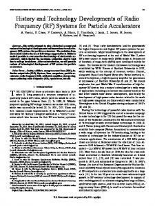
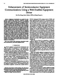
Figure 1a. The simulation model of the photonic-based RF generation with optical-pulse compression in an optical fiber. An optical two tone was used as the optical pulse source.
2. Simulation In this section, we describe a numerical simulation for the RF output-power enhancement by optical-pulse compression. Figure 1 shows the simulation model of the photonic-based RF generation. In Figure 1a, an optical two tone with a repetition frequency of f RF was used as the optical-pulse source. In Figure 1b, a Mach-Zehnder modulator generated optical pulses with a repetition frequency of f RF . The Mach-Zehnder modulator pulses were generated as follows. Single-frequency continuouswave (CW) laser light, generated by a CW laser (CWL), was intensity modulated with a Mach-Zehnder modulator. The operating point of the Mach-Zehnder modulator was set to minimum transmission with a dc bias voltage. The MachZehnder modulator was then driven by an RF sine wave with a repetition frequency of f RF 2 and the amplitude of the half-wave voltage of the Mach-Zehnder modulator. The resultant Mach-Zehnder modulator’s output was carriersuppressed return-to-zero with a frequency of f RF , where the optical phase was reversed from one pulse to the next. The optical pulse was transmitted in an optical fiber in order to perform optical-pulse compression, and detected with a photodetector. A variable optical attenuator (VOA) was used to keep the average power to the photodetector constant. Finally, the RF power with the f RF component was measured. We set f RF 20 GHz in order to simulate the experiment that will be described later.
Figure 1b. The simulation model of the photonic-based RF generation with optical-pulse compression in an optical fiber. A Mach-Zehnder modulator generated the optical pulses. The electric field of the optical pulse during the fiber transmission was obtained by solving the generalized nonlinear Schrödinger equation (GNLSE),
A i 2 z 2
2
A
t
2
3
6
3
A
t3
2
2
A i A A,
(1)
where A , z , t , â2 , â3 , á , and were the electric field, transmission distance, time, second-order dispersion, third-order dispersion, loss, and nonlinear coefficient, respectively [15]. Here, we ignored higher-order effects, such as forth-order dispersion and the Raman effect. In this simulation, we supposed the use of standard single-mode fiber (SSMF) as the optical fiber so that the dispersion parameter was D 17 ps/nm/km, the dispersion slope was Ds 0.06 ps/nm 2 /km , the loss coefficient was 0.2 dB/km, the Kerr coefficient was n2 2.2 10 20 m 2 /W , and the effective area was Aeff 80 μm 2 , respectively. After the electric field of the transmitted optical pulse was obtained, the generated RF output power PRF was obtained from the following equation:
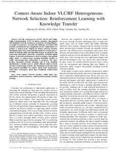
Figure 2. The calculated optical pulse in the case of an optical two tone, where the peak optical power at z 0 km was 200 mW. (a) The plot shows the optical pulse’s propagation, and (b) and (c) show optical-pulse waveforms at z 0 km and z 7.0 km, respectively.
The
Radio Science Bulletin No 361 (June 2017)
27
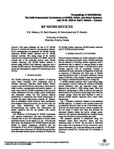
Figure 3. The calculated optical pulse for the case of a Mach-Zehnder modulator pulse where the peak optical power at z 0 km was 150 mW. (a) The plot shows the optical pulse’s propagation, and (b) and (c) show opticalpulse waveforms at z 0 km and z 7.4 km, respectively.
PRF
ZR
2
P (t )
2 f
f RF
,
(2)
where Z , R , P(t ) are the impedance of the RF circuit, the responsivity of the photodetector, and the optical intensity waveform at the photodetector, respectively, and denotes complex Fourier transformation. Using Equation (2), we calculated the RF gain due to optical-pulse compression, which is defined as the ratio of the RF power obtained from the transmitted optical pulse to the RF power without fiber transmission. Figure 2 shows the calculated optical pulse for the case of an optical two tone where the peak optical power at z 0 km was 200 mW. Figure 2a shows the optical-pulse propagation. The optical pulse was compressed after the fiber propagation, and the pulse width was minimized at fiber length of 7.0 km. Figures 2b and 2c show the opticalpulse waveforms at z 0 km and z 7.0 km, respectively. The 25.0 ps optical-pulse width was compressed to 11.7 ps after the fiber transmission. Figure 3 shows the calculated optical pulse for the case of the Mach-Zehnder modulator pulse. The peak optical power at z 0 was 150 mW, where the average optical power was the same as that of the optical two tone. Figure 3a
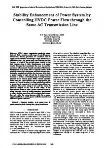
shows the optical-pulse propagation. The optical pulse was compressed after the fiber propagation, and the pulse width was minimized at a fiber length of 7.4 km. Figures 3b and 3c show the optical-pulse waveforms at z 0 km and z 7.4 km, respectively. The 33.4 ps optical-pulse width at the Mach-Zehnder modulator output was compressed to be 11.5 ps after the fiber transmission. We next calculated the optical-pulse width and the RF gain due to optical-pulse compression as a function of initial peak power to the fiber, P0 , and the transmission distance. Figure 4 shows the results for the case of an optical two tone. Figures 4a and 4b show the optical-pulse width and the RF gain, respectively. By increasing P0 , a narrower optical pulse could be obtained, and maximum RF gain at the optimized transmission distance was increased. RF gain was not obtained when P0 was low, i.e., without optical-fiber nonlinearity. Figure 4c shows the maximum RF gain and the transmission distance where the RF gain was maximized as functions of P0 . The RF gain was maximized at a transmission distance of between 3.2 km and 8.9 km, where P0 was 30 dBm. The maximum RF gain increased up to 5.1 dB when P0 was 26.3 dBm at a transmission distance of 5.9 km. Figure 5 shows the results for the case of a MachZehnder modulator pulse. Figures 5a and 5b show the
Figure 4. The calculated optical-pulse width and RF gain due to optical-pulse compression as functions of the initial peak power to the fiber, P0 , and the transmission distance, with an optical two tone. (a) and (b) show the optical pulse width and the RF gain, respectively. (c) shows the maximum RF gain and the transmission distance where the RF gain is maximized as functions of P0 .
28
The
Radio Science Bulletin No 361 (June 2017)
Figure 5. The calculated optical pulse width and RF gain due to optical-pulse compression as functions of the initial peak power to the fiber, P0 , and the transmission distance, with a Mach-Zehnder modulator pulse. (a) and (b) show the optical-pulse width and the RF gain, respectively. (c) shows the maximum RF gain and the transmission distance where the RF gain is maximized as functions of P0 .
optical-pulse width and the RF gain, respectively. By increasing P0 , a narrower optical-pulse could be obtained, and the maximum RF gain at the optimized transmission distance was increased, as in the case of the optical two tone. Figure 5c shows the maximum RF gain and the transmission distance where the RF gain was maximized as functions of P0 . The RF gain was maximized at a transmission distance of between 3.8 km and 9.2 km, where P0 was 30 dBm. The maximum RF gain increased up to 8.0 dB when P0 was 29.5 dBm at a transmission distance of 4.0 km. As will be described in Section 3.1, the PRF obtained by the Mach-Zehnder modulator pulse without fiber transmission was 2.6 dB lower than that of the optical two tone. The RF power obtained at this point was therefore 5.4 dB higher than that obtained by an optical two tone with the same average optical power, while the theoretical limit was 6 dB. It should be noted that when P0 decreased 5 dB, the RF gain decreased only 0.4 dB. It should also be noted that a fair amount of RF gain was obtained even though P0 was low. For example, when P0 was 10 dBm, the maximum RF gain of 4.5 dB was obtained with a transmission distance of 9.2 km.
Figure 6. The measurement principle for confirming the RF output-power enhancement with a narrower optical pulse.
The
Radio Science Bulletin No 361 (June 2017)
3. Experiment 3.1 RF Output-Power Enhancement with Narrower Optical Pulse We performed an experiment in order to confirm the RF-power enhancement due to the use of a narrower optical pulse. The measurement principle is shown in Figure 6. First, we illuminated a photodetector with an optical two tone with an average power of Pave , and measured the generated RF power, PRF 0 , with an RF spectrum analyzer (RFSA). PRF 0 was used as a reference power. We then illuminated the photodetector with several kinds of optical pulses with the same average power, Pave , and measured the generated RF power, PRF . The amplification factor, FA , defined by PRF PRF 0 , was then obtained. In this experiment, we set the repetition frequency of the optical
Figure 7. The measured and calculated amplification factors of a 10-GHz RF output as functions of the normalized pulse width.
29
Figure 8. The experimental setup for the photonic-based RF generation with outputpower enhancement due to the optical-pulse compression. pulse to be 10 GHz. The bandwidth of the photodetector used in the experiment was 8 GHz. Figure 7 shows the measured and the calculated FA values of the 10 GHz RF output as functions of the pulse width, normalized by the repetition period. For an optical two tone, the normalized pulse width was 0.5, and FA was 0 dB. The 3 ps and 13 ps points show the results when 3 ps and 13 ps optical pulses, generated from an actively mode-locked fiber ring laser, were illuminated onto the photodetector. The MZM point shows the result when the optical pulse was generated with a Mach-Zehnder modulator with the same operating conditions described in the previous session, except for f RF 10 GHz. The normalized pulse width was 0.33, and FA was 2.6 dB. The Gaussian and sech2 curves show the calculated values when the optical pulse was a Gaussian pulse and a hyperbolic-secant pulse, respectively. The measured results were well consistent with the calculated results. It was clearly seen that when the pulse width was narrower, the amplification factor, FA – i.e., the RF output power – was increased [11].
3.2 RF Output Power Enhancement by Optical Pulse Compression We next performed an experiment in order to confirm the RF power enhancement due to optical-pulse compression. Figure 8 shows the experimental setup. A CW laser output with a wavelength of 1550 nm was phase modulated with a phase modulator (PM) in order to reduce the influence of stimulated Brillouin scattering (SBS) [16]. The modulation frequency, f PM , was 300 MHz. The phase modulator’s output was intensity modulated with a MachZehnder modulator. A dc bias voltage was set to the minimum transmission point of the Mach-Zehnder modulator. The driving RF voltage to the Mach-Zehnder modulator was adjusted in such a way that the first-order sideband power to the third-order sideband power was 18.7 dB, using the optical spectrum analyzer (OSA). The driving condition of the Mach-Zehnder modulator then became the same as that used in the simulation. We set f RF 2 10 GHz. In the
Figure 9. The measured and calculated results in the case of an optical two tone. (a) and (b) show the observed and simulated optical waveforms at fiber lengths of 0 km and 7.5 km, respectively. (c) shows the measured and calculated RF gains and pulse widths as functions of the fiber length.
30
The
Radio Science Bulletin No 361 (June 2017)
Figure 10. The measured and calculated results in the case of a Mach-Zehnder modulator pulse. (a) and (b) show the observed and simulated optical waveforms at fiber lengths of 0 km and 7.5 km, respectively. (c) shows the measured and calculated RF gains and pulse widths as functions of the fiber length. case of the optical two tone, the Mach-Zehnder modulator output was filtered by a fiber Bragg grating (FBG) with a bandwidth of 0.15 nm in order to suppress higher-order sidebands. The output was amplified with an erbium-doped fiber amplifier (EDFA) to an average power of 20.0 dBm, corresponding to a peak power for the Mach-Zehnder modulator pulse and the optical two tone of 21.8 dBm and 23.0 dBm, respectively. The amplified optical pulses were transmitted in a standard single-mode fiber, and were attenuated with a variable optical attenuator for setting the average optical power, Pave , to the photodetector to be 1.0 dBm. In a practical case, the variable optical attenuator is useful in order to prevent damage to the photodetector. The bandwidth of the photodetector used in the experiment was 20 GHz. The photodetector output RF power, PRF , was measured by an RF spectrum analyzer (RFSA). The optical intensity waveform to the photodetector was also observed with an optical sampling oscilloscope (OSO). We changed the fiber length to values of 0 km, 2.5 km, 5.0 km, 7.5 km, 10.0 km, and 12.5 km.
From the results described above, we confirmed the RF output-power enhancement due to optical-pulse compression with a standard single-mode fiber.
Figure 9 shows the measured and calculated results for the case of an optical two tone. Figures 9a and 9b show the observed and simulated optical waveforms at fiber lengths of 0 km and 7.5 km, respectively. Figure 9c shows the measured and calculated RF gains and pulse widths as functions of the fiber’s length. The measured results showed good agreement with the calculated results. When the fiber length was 7.5 km, the measured and calculated pulse widths were 12.5 ps and 11.7 ps, respectively, and the measured and calculated RF gains were 4.2 dB and 4.1 dB, respectively. Figure 10 shows the measured and calculated results for the case of a Mach-Zehnder modulator pulse. Figures 10a and 10b show the observed and simulated optical waveforms at fiber lengths of 0 km and 7.5 km, respectively. Figure 10c shows the measured and calculated RF gains and pulse widths as functions of the fiber’s length. The measured results showed good agreement with the calculated results. When the fiber length was 7.5 km, the measured and calculated pulse widths were 11.4 ps and 11.5 ps, respectively, and the RF gains were 6.6 dB and 6.4 dB, respectively.
Let us suppose that the optical pulse is the MachZehnder modulator pulse, f RF is 50 GHz ( 1 0.4 ) and nonzero dispersion-shifted fiber (NZ-DSF) is used as the transmission fiber, where D 2 ps/nm/km ( 2 0.12 ) and Aeff 50 μm 2 ( 3 1.6 ). In this case, the same RF gain of 8.0 dB is expected when the initial peak power, P0 is 26.1 dBm and the transmission distance is 5.5 km. In this argument, we neglected the loss and the third-order dispersion terms, since those parameters are difficult to control and the transmission distance is not so long. If f RF becomes very high and low-dispersion fiber, such as DSF, is used – in other words, higher-order dispersion lengths become comparable to the second-order dispersion length – the higher-order dispersions need to be considered. In order to check the validity of the expected RF gain, we calculated the RF gain by solving the generalized nonlinear Schrödinger equation with loss and third-order dispersion (0.2 dB/km and 0.6 ps/nm 2 /km ). The RF gain obtained was 8.0 dB, which was the same as that obtained by the scaling law. When f RF was 75 GHz ( 1 0.27 ) and the same nonzero dispersion-shifted fiber was used, an RF gain
The
Radio Science Bulletin No 361 (June 2017)
4. Toward High-Frequency Generation According to the scaling law of the generalized nonlinear Schrödinger equation [17], it turns out that when the variables t , â2 , , z , â3 , á , and A are 2 converted to T 1t , B2 2 2, 3 , Z 1 2 z 2 2 B3 , , and U Al 1 2 3 2 1 3 A , the 2 1 differential equation of U with respect to Z and T exactly takes the same form as Equation (1). This means that if parameters such as the RF frequency ( t 1 ), fiber length, and dispersion, and optical power are changed in accordance with the above relationships, the RF gain exactly becomes the same. This gives us a design guideline towards high-frequency RF generation.
31
Table 1. The design parameters for high-frequency RF generation. z and P0 were obtained from the scaling law, and the RF gain was obtained by solving the generalized nonlinear Schrödinger equation. See the text for details of the fiber’s specifications. z f RF Fiber Type P0 RF Gain [km] [GHz] [dBm] [dB] 20 SSMF 4.0 29.5 8.0 MMZ 50 NZ-DSF 5.5 26.1 8.0 75 NZ-DSF 2.4 29.6 8.0 20 SSMF 5.9 26.4 5.1 50 NZ-DSF 8.0 23.0 5.1 75 NZ-DSF 3.6 26.5 5.2 Optical 2 tone NZ-DSF 2.0 29.0 5.2 100 HNLF 4.0 18.1 4.8 300 HNLF 0.4 27.6 5.1 Pulse Source
of 8.0 dB was expected when P0 was 29.6 dBm and the transmission distance was 2.4 km. The RF gain obtained by solving the generalized nonlinear Schrödinger equation was also 8.0 dB. As described in Sections 2 and 3.1, the RF gain due to optical-pulse compression of the Mach-Zehnder modulator pulse corresponded to an FA of 5.4 dB. We next made the same calculation for the optical two tone. When f RF was 50 GHz and the same nonzero dispersion-shifted fiber was used as the transmission fiber, the same RF gain of 5.1 dB was expected by the scaling law when P0 was 23.0 dBm and the transmission distance was 8.0 km. The same RF gain was obtained by solving the generalized nonlinear Schrödinger equation with loss and third-order dispersion. When f RF was 75 GHz and the nonzero dispersion-shifted fiber was used, the same RF gain was expected when P0 was 26.5 dBm and the transmission distance was 3.6 km. An RF gain of 5.2 dB was obtained by solving the generalized nonlinear Schrödinger equation. When f RF was 100 GHz ( 1 0.2 ), the same RF gain was expected when P0 was 29.0 dBm and the transmission distance was 2.0 km. An RF gain of 5.2 dB was obtained by solving the generalized nonlinear Schrödinger equation. These results are summarized in Table 1. As could be seen in the scaling law, P0 is proportional 2 to f RF and inversely proportional to D . The use of nonzero dispersion-shifted fiber is effective in reducing P0 for high-frequency generation as described above. However, P0 exceeded 30 dBm when f RF 100 GHz. In that case, highly nonlinear fiber (HNLF) is necessary as the transmission fiber. When f RF was 100 GHz and a highly nonlinear fiber where D 1 ps/nm/km ( 2 0.06 ) and 12W 1 /km ( 3 10.7 ) is used, an RF gain of 5.1 dB was expected when P0 was 18.1 dBm and the transmission distance was 4.0 km. The RF gain from solving the generalized nonlinear Schrödinger equation with loss and third-order dispersion (1 dB/km and 0.02 ps/nm2 /km ) was 4.8 dB. The small discrepancy in the RF gain came from the attenuation due to the loss of the highly nonlinear
32
FA [dB] 5.4 5.4 5.4
fiber. When f RF was 300 GHz, the same RF gain was expected when P0 was 27.6 dBm and the transmission distance was 0.4 km. The same RF gain of 5.1 dB was obtained by solving the generalized nonlinear Schrödinger equation, since the attenuation was negligible.
5. Conclusion We proposed to use optical-pulse compression in a standard optical fiber in order to enhance the output power in photonic-based RF generation with a Mach-Zehnder modulator and an optical two tone. We numerically analyzed optical-pulse propagation using the generalized nonlinear Schrödinger equation, and obtained the RF gain due to optical-pulse compression. We experimentally confirmed that the RF output power was enhanced by the use of a narrower optical pulse and optical-pulse compression. In the 20-GHz RF generation experiment using a standard single-mode fiber and a Mach-Zehnder modulator pulse, an RF gain of 6.6 dB due to optical-pulse compression was obtained at a fiber length of 7.5 km and a launched average power to the fiber of 20.0 dBm. With an optical two tone, an RF gain of 4.2 dB was obtained with the same fiber length and launched average power to the fiber. Using the scaling law of the generalized nonlinear Schrödinger equation, we found that 50-GHz, 75-GHz, and 100-GHz generation with RF gain was possible with realistic optical power if nonzero dispersion-shifted fiber was used as the transmission fiber, whereas highly nonlinear fiber was necessary for 300-GHz RF generation.
6. Acknowledgement This research was supported by “Radio technologies for 5G using Advanced Photonic Infrastructure for Dense user environments (RAPID),” the Commissioned Research of NICT, Japan, and SCOPE #165003010, The Ministry of Internal Affairs and Communications, Japan, to which the authors would like to express their gratitude. The
Radio Science Bulletin No 361 (June 2017)
7. Reference 1. J. Yao, “Microwave Photonics,” Journal of Lightwave Technology, 27, 3, February 2009, pp. 314-335. 2. J. A. Nanzer, P. T. Callahan, M. L. Dennis, and T. R. Clark, Jr., “Photonic Signal Generation for MillimeterWave Communications,” Johns Hopkins APL Technical Digest, 30, 4, January 2012, pp. 299-308. 3. K. Jung and J. Kim, “All-Fibre Photonic Signal Generator for Attosecond Timing and Ultralow-Noise Microwave,” Scientific Reports, 5, 16250, November 2015, pp. 1-7. 4. X. S. Yao and L. Maleki, “Optoelectronic Microwave Oscillator,” Journal of the Optical Society of America B, 13, 8, August 1996, pp. 1725-1735. 5. Y. Li, A. Rashidinejad, J. -M. Wun, D. E. Leaird, J.-W. Shi, and A. M. Weiner, “Photonic Generation of WBand Arbitrary Waveforms with High Time-Bandwidth Products Enabling 3.9 mm Range Resolution,” Optica, 1, 6, December 2014, pp. 446-454. 6. T. Nagatsuma, S. Horiguchi, Y. Minamikata, Y. Yoshimizu, S. Hisatake, S. Kuwano, N. Yoshimoto, J. Terada, and H. Takahashi, “Terahertz Wireless Communications Based on Photonics Technologies,” Optics Express, 21, 20, October 2013, pp. 23736-23747. 7. D. A. Tulchinsky, J. B. Boos, D. Park, P. G. Goetz, W. S. Rabinovich, K. J. Williams, “High-Current Photodetectors as Efficient, Linear, and High-Power RF Output Stages,” Journal of Lightwave Technology, 26, 4, February 2008, pp. 408-416. 8. X. Xie, Q. Zhou, K. Li, Y. Shen, Q. Li, Z. Yang, A. Beling, J. C. Campbell, “Improved Power Conversion Efficiency in High-Performance Photodiodes by Flip-Chip Bonding on Diamond,” Optica, 1, 6, 2014, pp. 429-435.
10. M. N. Hutchinson, V. J. Urick, and N. J. Frigo, “Power Photodiodes for High Dynamic Range Photonic Links,” Applied Optics, 54, 31, November 2015, pp. F17-F24. 11. A. Hirata, M. Harada, and T. Nagatsuma, “120-GHz Wireless Link Using Photonic Techniques for Generation, Modulation, and Emission of Millimeter-Wave Signals,” Journal of Lightwave Technology, 20, 10, October 2003, pp. 2145-2153. 12. F.-M. Kuo, J.-W. Shi, H.-C. Chiang, H.-P. Chuang, H.-K. Chiou, C.-L. Pan, N.-W. Chen, H.-J. Tsai, and C.-B. Huang, “Spectral Power Enhancement in a 100 GHz Photonic Millimeter-Wave Generator Enabled by Spectral Line-by-Line Pulse Shaping,” IEEE Photonics Journal, 2, 5, 2010, pp. 719-727. 13. J. -M. Wun, H. -Y. Liu, C. -H. Lai, Y. -S. Chen, S. -D. Yang, C. -L. Pan, J. E. Bowers, C. -B. Huang, and J. -W. Shi, “Photonic High-Power 160-GHz Signal Generation by Using Ultrafast Photodiode and a High-RepetitionRate Femtosecond Optical Pulse Train Generator,” IEEE Journal of Selected Topics in Quantum Electronics, 20, 6, November 2014, p. 3803507. 14. T. Yamaguchi, H. Morimoto, H. Toda, “Output Power Enhancement by Optical Pulse Compression in Photonic-Based RF Generation,” in Proceedings of URSI AP-RASC, August 2016, pp. 1528-1530. 15. G. P. Agrawal, Nonlinear Fiber Optics, Fifth Edition, New York, Academic Press, 2013, Chapter 2. 16. A. Kobyakov, M. Sauer, and D. Chowdhury, “Stimulated Brillouin Scattering in Optical Fibers,” Advances in Optics and Photonics, 2, 1, March 2010, pp. 1-59. 17. D. Marcuse and C. R. Menyuk, “Simulation of SingleChannel Optical Systems at 100 Gb/s,” Journal of Lightwave Technology, 17, 4, April 1999, pp. 564-569.
9. E. Rouvalis, F. N. Baynes, X. Xie, K. Li, Q. Zhou, F. Quinlan, T. M. Fortier, S. A. Diddams, A. G. Steffan, A. Beling, and J. C. Campbell, “High-Power and HighLinearity Photodetector Modules for Microwave Photonic Applications,” Journal of Lightwave Technology, 32, 20, 2014, pp. 3810-3816.
The
Radio Science Bulletin No 361 (June 2017)
33