Aug 15, 2003 - We present an approach, rigorous automated network security man- .... labor among devices at different points in a network ensures policy ...... leave the company in an IPsec tunnel; a financial policy about what traffic.
Rigorous Automated Network Security Management∗ Joshua D. Guttman
Amy L. Herzog
The MITRE Corporation {guttman, aherzog}@mitre.org August 15, 2003
Abstract Achieving a security goal in a networked system requires the cooperation of a variety of devices, each device potentially requiring a different configuration. Many information security problems may be solved with appropriate models of these devices and their interactions, and giving a systematic way to handle the complexity of real situations. We present an approach, rigorous automated network security management, which front-loads formal modeling and analysis before problemsolving, thereby providing easy-to-run tools with rigorously justified results. With this approach, we model the network and a class of practically important security goals. The models derived suggest algorithms which, given system configuration information, determine the security goals satisfied by the system. The modeling provides rigorous justification for the algorithms, which may then be implemented as ordinary computer programs requiring no formal methods training to operate. We have applied this approach to several problems. In this paper we describe two: distributed packet filtering and the use of IP security (IPsec) gateways. We also describe how to piece together the two separate solutions to these problems, jointly enforcing packet filtering as well as IPsec authentication and confidentiality on a single network.
∗ Supported by the National Security Agency under contract DAAB07-99-C-C201, and the United States Air Force under contract F19628-99-C-0001. Preliminary versions of parts of this material appeared in Proceedings, 1997 IEEE Symposium on Security and Privacy; Proceedings, ESORICS 2000 ; and Proceedings, VERIFY 2002.
1
Contents 1 Introduction
3
2 Packet-Filtering Devices 2.1 Modeling . . . . . . . . . . . . . . . . . . . 2.1.1 Modeling Networks . . . . . . . . . . 2.1.2 Modeling Packets . . . . . . . . . . . 2.1.3 Devices and Filtering Postures . . . 2.1.4 Paths and Trajectories . . . . . . . . 2.2 Expressing Security Goals . . . . . . . . . . 2.2.1 Policy Statements and Policies . . . 2.3 Deriving Algorithms . . . . . . . . . . . . . 2.3.1 Checking a Posture . . . . . . . . . . 2.3.2 Generating a Posture . . . . . . . . 2.4 Implementing: Network Policy Enforcement 2.4.1 NPT and the Atomizer . . . . . . . 2.4.2 Interpreting Access Lists . . . . . . . 2.4.3 The NPE Tools . . . . . . . . . . . . 3 The 3.1 3.2 3.3
3.4
3.5
. . . . . . . . . . . . . .
. . . . . . . . . . . . . .
. . . . . . . . . . . . . .
. . . . . . . . . . . . . .
. . . . . . . . . . . . . .
. . . . . . . . . . . . . .
. . . . . . . . . . . . . .
. . . . . . . . . . . . . .
. . . . . . . . . . . . . .
. . . . . . . . . . . . . .
. . . . . . . . . . . . . .
. . . . . . . . . . . . . .
4 5 5 6 7 7 8 9 10 10 11 12 12 13 14
IP Security Protocols (IPsec) 15 IP Security . . . . . . . . . . . . . . . . . . . . . . . . . . . . . . 17 Modeling . . . . . . . . . . . . . . . . . . . . . . . . . . . . . . . 19 Expressing Security Goals . . . . . . . . . . . . . . . . . . . . . . 23 3.3.1 Authentication Goals . . . . . . . . . . . . . . . . . . . . 23 3.3.2 Confidentiality Goals . . . . . . . . . . . . . . . . . . . . . 23 3.3.3 Example Goals . . . . . . . . . . . . . . . . . . . . . . . . 24 3.3.4 Trust Sets . . . . . . . . . . . . . . . . . . . . . . . . . . . 24 Deriving Algorithms . . . . . . . . . . . . . . . . . . . . . . . . . 25 3.4.1 Authentication . . . . . . . . . . . . . . . . . . . . . . . . 27 3.4.2 Unwinding . . . . . . . . . . . . . . . . . . . . . . . . . . 28 3.4.3 Confidentiality . . . . . . . . . . . . . . . . . . . . . . . . 30 3.4.4 Manageability . . . . . . . . . . . . . . . . . . . . . . . . . 32 Implementation: The Confidentiality and Authentication IPsec Checker (CAIC) . . . . . . . . . . . . . . . . . . . . . . . . . . . 32 3.5.1 CAIC Input . . . . . . . . . . . . . . . . . . . . . . . . . . 33 3.5.2 Goal Enforcement Checking and Output . . . . . . . . . . 34
4 Combined Packet Filtering and IPsec 35 4.1 Expressing Security Goals . . . . . . . . . . . . . . . . . . . . . . 35 4.2 Deriving Algorithms . . . . . . . . . . . . . . . . . . . . . . . . . 37 5 Conclusion
38
2
1
Introduction
Controlling complexity is a core problem in information security. In a networked system many devices, such as routers, firewalls, virtual private network gateways, and individual host operating systems must cooperate to achieve security goals. These devices may require different configurations, depending on their purposes and network locations. To solve many information security problems, one needs models of these devices and their interactions. We have focused for several years on these problems, using rigorous automated network security management as our approach. Rigorous automated security management front-loads the mathematical work needed for problem-solving. Rigorous analysis is needed to solve many information security problems, but unfortunately specialists in modeling are in short supply. We focus the modeling work on representing behavior as a function of configurations, and predicting the consequences of interactions among differently configured devices. A useful model must also allow one to express a class of practically important security goals. The models suggest algorithms that take as input information about system configuration, and tell us the security goals satisfied in that system. Sometimes we can also derive algorithms to generate configurations to satisfy given security goals. The soundness of the algorithms follows from the models. However, the algorithms are implemented as computer programs requiring no logical expertise to use. Resolving individual practical problems then requires little time and no formal methods specialists, while offering a good level of the higher assurance of security. Our purpose in this paper is to illustrate the rigorous security management approach. We describe a group of problems and the modeling frameworks that lead to their solutions. One problem concerns distributed packet filtering, in which packet-filtering routers are located at various points in a network. The problem is to constrain the flow of different types of packets through the network. Another problem concerns gateways running the IP security protocols (IPsec); the problem is to ensure that authentication and confidentiality goals are achieved for specific types of packets traversing the network. We have implemented solutions to these problems [7, 8, 10]. The goal of the present paper is to provide an integrated description of our methods, and also to unify the two solutions, so that packet filtering goals and IPsec goals are jointly enforced on a network. Steps in Rigorous Automated Security Management The method requires four steps. Modeling: Construct a simple formal model of the problem domain. For instance, the packet filtering system model contains a bipartite graph, in which nodes are either routers or network areas. Edges represent interfaces, and each interface may have packet filters representing the set of packets permitted to traverse that edge in each direction. 3
Expressing Security Goals: Selecting a model constrains which security goals are expressible, so that model simplicity must be balanced against the ability to represent core security problems. Within each model, identify one or a few security goal forms that define security-critical aspects of the system. In our treatment of IPsec, one goal form characterizes assertions about authenticity; confidentiality is expressed using a different goal form. People managing a particular system will choose a number of goals of these general forms as expressing the properties they need for their system. Thus, it is crucial that these goal forms express at least some of the most important security considerations that the system managers need to achieve. Deriving Algorithms: The system model and security goal forms must be chosen so that algorithms can determine if goals are enforced in a particular system. Each specific system configuration (abstracting from characteristics not reflected in the model) is a problem instance, for which the analysis algorithms must determine whether given goals are achieved. In some cases, another algorithm may, given some information about a system and some desired goal statements, fill in the details to determine a way for the system to satisfy the goals. The rigor in our method lies in the mathematical character of the model and the opportunity to give convincing proofs of correctness for these algorithms. Implementing: Having defined and verified one or several goal enforcement algorithms in the previous step, one writes a program to check goal enforcement. The inputs to this program consist of goal statements that should be enforced, and system configuration information. For instance, in our packet filtering example, the system configuration information consists of network topology information, and the router configuration files. The program then enumerates which goals are met, and gives counterexamples for unmet goals. The program may also generate new and better configuration files.
2
Packet-Filtering Devices
Packet filtering devices such as routers, firewall systems, and IPsec gateways are an important component of network layer access control. Since packets passing from one area in a network to another often traverse many intermediate points, and may travel via alternate routes, filtering devices in several locations may need to cooperate. It is difficult to determine manually what division of labor among devices at different points in a network ensures policy enforcement, particularly given multiple routes. This is a problem of localization. We will describe this problem from the rigorous automated security management vantage point, stressing the four steps: modeling (Section 2.1), defining
4
� �
External � � � � �
Periphery
Allied
� @ � � @ @
Engineering
�
�
�
�
� � @ @
Finance
� �
�
�
Figure 1: Corporate Protection Example
security goals (Section 2.2), developing algorithms to enforce these goals (Section 2.3), and implementing the algorithms (Section 2.4).
2.1
Modeling
Our model has two parts, namely a model of networks as undirected bipartite graphs (Section 2.1.1), and a model of packets as having certain distinguishable characteristics (Section 2.1.2). 2.1.1
Modeling Networks
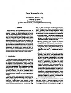
We regard a network as a bipartite graph. The nodes of the graph are areas, collections of hosts and networks which are similar in terms of security policy; and devices, which are dual-homed hosts or packet filtering routers connecting the areas and moving packets between them. There is an (undirected) edge between a filtering device and an area if the device has at least one interface on that area. Thus, areas and devices are the two sorts of node in our network graph, and we use variables such as a and d to range over them (respectively). In Figure 1, Engineering, External, Allied, etc. are areas, and the black squares indicate filtering devices. This diagram represents a corporation that owns the three networks marked Engineering, Finance, and Periphery. The Internet, indicated as External, is connected to the corporation via a filtering device at Periphery. However, the engineering staff have long term collaborative relations with another organization called Allied, and must exchange different network services with their collaborators than would be acceptable with other organizations. Hence, there is also a dedicated network connection (and filtering point) between them. Such situations where different trust relations attach to different portions of a network are common. Our problem is to reliably enforce a security policy sensitive to these differences. Trust relations must be translated to filtering decisions in a way sensitive to the topology of the network. Formalizing a real-world network takes some care. We can express access control policies on the network only if they involve the flow of packets from one 5
area to a different area. We cannot express requirements on packets traveling within a single area, nor could we enforce them. Thus, security goals for a particular network must determine the granularity of its model. In addition, we must ensure that all of the real-world connectivity between distinct areas in our networks is represented. We cannot enforce access controls on the traffic between areas if we do not know what filtering devices (or dualhomed hosts) may move packets from one area to another. On the other hand, the areas may represent large collections of physical networks that have many routers within them. Those internal devices are of no interest for our analysis. This point is highly relevant to the usability of our method. Large networks, administered by a single authority, typically use relatively few routers as filtering devices. Thus, substantial practical problems arise with networks not much more complicated than the one shown in Figure 1. Indeed, often there are different layers of administrative control. For example, enterprise-level network administration may be concerned with policy among large corporate units, the Internet, and strategic business partners. By contrast, a corporate laboratory may have more specific requirements concerning communication among its distributed portions, located within different large corporate units. Their point of view distinguishes smaller components within them, and may lump the remainder together as a single area providing transport among these smaller units. Enforcement for their policy may depend on an entirely separate collection of filtering devices, typically also of modest size. 2.1.2
Modeling Packets
In our modeling, we need only consider an aspect of packets if a device that filters and routes packets may be sensitive to it. Generally speaking, these are the source and destination addresses, the protocol (such as tcp, icmp, and so forth), and certain protocol-specific fields. Protocol-specific fields include the source and destination ports in the case of tcp or udp; message type in the case of icmp and igmp, and for icmp additionally a message code; and an additional bit in the case of tcp indicating whether the packet belongs to an already established connection. We ignore many other characteristics such as the payload, the source-routing history, time-to-live, and checksum. These are the only packet properties that are available to configure a Cisco router for packet filtering [5]. Other filtering methods such as ip Chains and ip Filters give loosely similar expressiveness for properties of packets [21, 20]. We refer to a possible value of these fields as an abstract packet. We regard an abstract packet as a single item in our model, even though it represents many concrete ip packets. These ip packets are indiscernible, as far as we are concerned, so our theory identifies them into a single abstract packet. The boolean algebra of sets of abstract packets allows us to represent filter behavior and to express what dangers a security policy seeks to prevent. Our model consists of essentially only these two ingredients, namely a bipartite graph representing the network and this notion of abstract packet (together with the boolean algebra of sets of them). The remainder of the notions we 6
need are defined in terms of these ingredients, notably paths, trajectories, and security postures, which we will explain in Sections 2.1.3 and 2.1.4. 2.1.3
Devices and Filtering Postures
A filtering device in our model is a node with interfaces on one or more network areas. Thus, we regard an interface as an edge between that node and the node representing the network area. Packets flow in both directions across this edge. Most filtering devices can be configured to discard packets passing in either direction across any interface, and they typically pass different packets depending on the direction of flow. Thus, from our point of view, an edge between an area a and a device d is characterized by two sets of abstract packets: inb(a, d) defines the packets permitted to traverse the edge inbound into the device from the area, while outb(a, d) defines the packets permitted to traverse the edge outbound from the device to the area. A filtering posture for a particular network (i.e. a bipartite graph) consists of an assignment of sets inb(a, d) and outb(a, d) to each pair a, d such that d is a device having an interface onto the area a. We have no interest in distinguishing different interfaces that the filtering device may have on the same area. They cannot control the flow of packets in any additional useful ways. 2.1.4
Paths and Trajectories
A path through the network is a sequence of immediately connected nodes on the associated bipartite graph. We ignore issues of routing in our current presentation, so that our conclusions will hold even on the conservative assumption that routing tables may change unpredictably. Thus, a packet may potentially traverse any path through the network. Routing information may be easily incorporated into the model if desired, and the tool we describe in Section 2.4 has an option to determine whether to consider routing. A trajectory is a path π taken by a packet p, which we regard as simply the pair (π, p) consisting of the path and the packet (i.e. an abstract packet). The trajectory is a crucial notion. The purpose of filtering devices is to ensure that some trajectories cannot occur. These are trajectories in which packets exercising vulnerable services are transmitted from untrusted hosts, and allowed to reach endpoints we would like to protect. Thus, security goals will be certain sets of trajectories, interpreted as the trajectories acceptable according to that policy. A configuration enforces a goal if it filters and discards a packet before it traverses a trajectory not in the set, interpreted as a trajectory contrary to the policy. Our definition of trajectory, as just given, effectively assumes that the state of the packet does not change as the packet traverses the network. A trajectory as defined here does not associate different packets (or distinguishable states of the traveling packet) with successive locations. (In Section 3 we consider an
7
elaborated notion of trajectory that does, as is necessary because the protocols we consider there depend on transforming the packet as it travels.)
2.2
Expressing Security Goals
Security goals rely upon two sorts of ingredient: 1. Which areas has the packet traversed ? For instance, was it once in the External area, and has it now reached the Engineering area? 2. What does the packet say? The contents of the packet are simply its properties as an abstract packet. For instance, if the destination port of the packet is port 53, then given the vulnerabilities in many dns implementations, we may wish to discard it unless the destination address is a carefully administered host we make available for external dns queries. Ingredient 1 concerns the actual path of the packet as it traverses the network, regardless of what it claims. Ingredient 2 concerns only what the packet claims, not where it has really passed. These two kinds of information diverge when filtering devices send packets through unexpected paths, or packets are spoofed, or packets are intercepted before reaching their nominal destinations. A useful notion of security policy must consider both kinds of information. As an example, suppose that in the network shown in Figure 1 we wish to have a dns server located in the Engineering area accessible only by company hosts. Then we may have a policy that no packet with destination port 53 that was ever in the External area should be delivered to the Engineering area. Here, the source field address of the packet is irrelevant. Even if the source address claims to be in the Periphery network, the packet should not be delivered. The attack may be contained in incoming packets without any reply packets actually needing to be returned to the original source host. In this case, the attacker may even prefer to adorn his attack packets with a source address within the organization. If the dns server is required to be accessible from the Periphery area, it is a derived security requirement that dns-directed packets with spoofed source addresses not be permitted to enter the Periphery from External. Once they have done so, it will no longer be possible to distinguish these suspicious ones from packets originating locally there, so that the bad packets can be filtered between Periphery and Engineering. We have thus illustrated that certain goals can be met only if filtering occurs at specific locations, where the decisions depend on the topology of the network and the goals to be achieved. Moreover, the goal that concerns us in this example concerns properties not only of the packet itself (its destination address and port being the dns server and port 53), but also of the path itself, since the packet is more apt to exercise a vulnerability if it has come into the organization from outside. A security policy should be a property of trajectories—a set of permissible packet-path pairs—so we can express goals like the one we have just described.
8
2.2.1
Policy Statements and Policies
We adopt a simple notion of network access control policy for the remainder of Section 2 that balances actual trajectory and header contents. A policy statement concerns two distinct areas occurring in the actual path of the packet, one earlier network area and one later network area. If φ is some predicate of packets, and p ranges over packets, then If p was previously in a1 and later reaches a2 , then φ(p) is a policy statement when a1 6= a2 . It requires that a2 be protected against non-φ packets if they have ever been in a1 . For instance, If p was ever in the External area and later reaches the Engineering area, then p should be an smtp packet with its destination an approved mail host would be a policy statement relevant to the corporate example pictured in Figure 1. In this policy statement, we aim to protect hosts in the Engineering area from attacks that might be transmitted from the External area; the only exception being that specific mail hosts are not protected against packets participating in the smtp protocol, i.e. tcp packets with destination port 25. It is also possible to interpret this form of statement as offering some confidentiality protection. In this interpretation, it states that a1 is protected against loss of data to a2 , if that data is carried only in packets p such that φ(p). For instance, a corporation may use outbound filtering to ensure that traffic with a database server cannot be misrouted outside its networks, since much sensitive business information is carried in these packets. It would also be possible to consider more complicated policy statements, involving e.g. three areas. As an example, we might require a packet that came from the External area via the Allied area and eventually reached the Engineering area to have: • an external address as its ip source field; • an internal address as its ip destination field; • a source or destination port of 25, indicating that it is an smtp packet. Other packets could not pass through the Allied area. However, realistic security goals appear to be expressible using two-area policy statements. In the case of our example, we could replace this three-area policy statement with a (slightly stronger) pair of two-area policy statements. The first would require that if a packet p that was in the External area reaches the Allied area, and if p has a destination address in the internal areas, then p’s source address should be in the External area and p’s service should be smtp. The second would require that if a packet p that was in the Allied area reaches the Engineering area, then p’s destination address should be in one of the internal areas. If this pair of two-area statements are satisfied, then the three-area 9
requirement will also be satisfied. The extra strength of these two-area statements was probably desired anyway: namely, that the corporation’s internal networks should not be used as a pass-through from the Allied organization. Therefore, for the remainder of Section 2, a policy statement will be a twoarea statement, asserting that any packet p that was in one area and later arrives in a different area meets some constraint φ(p). A policy will mean a set of policy statements, one for each pair of distinct areas a1 , a2 . The constraint may be vacuously true, allowing everything to pass between them; or else at the other extreme, unsatisfiable, requiring that nothing pass.
2.3
Deriving Algorithms
The ideas introduced in previous sections suggest two algorithms that exploit the boolean operations on constraints φ(p) in combination with the graph structure of the underlying network specification. These algorithms may be used to check a putative filtering posture, or to generate a filtering posture that will enforce a given policy. Both of these algorithms depend on the notion of the feasibility set of a path. Given a filtering posture hinb, outbi, the feasibility set of a path π is the set of all abstract packets that survive all of the filters traversed along the path. That is, if π traverses device d, entering it from area a1 , then an abstract packet p is in the feasibility set of π only if p ∈ inb(a1 , d). If π enters area a2 from d, then p is in the feasibility set of π only if p ∈ outb(a2 , d). We can compute the feasibility set of a path iteratively by starting with the set of all packets; as we traverse the inbound step from a1 to d, we take an intersection with inb(a1 , d); as we traverse the outbound step from d to a2 , we take an intersection with outb(a2 , d). Binary Decision Diagrams allow us to carry out such computations reasonably efficiently. We use this idea in both of the following sections. 2.3.1
Checking a Posture
To check that a posture enforces a policy P , we examine each path between areas to ensure that the feasibility set for that path is included in the policy statement for the areas it connects. If π is a path starting at area a0 and terminating at area ai , we must check that the feasibility set for π is included in P (a0 , ai ), i.e., the set of abstract packets that can actually traverse the path is a subset of the set of abstract packets permitted to travel from a0 to ai . Algorithmically, it is enough to check this property for noncyclic paths, as the feasibility set for a cyclic path π1 must be a subset of the feasibility set for any noncyclic sub-path π0 . The set of noncyclic paths is fairly small for reasonable examples; in the case of the corporate example, 40 noncyclic paths begin and end at areas (rather than at filtering devices).
10
2.3.2
Generating a Posture
Creating a posture is a more open-ended problem. There are essentially different solutions, different ways to assign filtering behavior, possibly to different devices or to different interfaces of a device, such that the net result enforces the global security policy. Outbound Filtering. Various posture generation algorithms can be based on the idea of “correcting” a preexisting filtering posture F = hinb, outbi. We say that F ′ tightens F if inb′ (a, d) ⊆ inb(a, d) and outb′ (a, d) ⊆ outb(a, d), for all a and d. Suppose that π is a path from area a0 to ai that enters ai from device d, and suppose that the feasibility set for π is φ. If φ is not a subset of the policy constraint P (a0 , ai ), then we can update F to a new filtering posture F ′ = hinb′ , outb′ i where F ′ differs from F only in that outb′ (ai , d) = outb(ai , d) \ (φ \ P (a0 , ai )) where φ \ ψ is the set difference of φ and ψ. F ′ tightens F to prevent any policy violations that would otherwise occur on the last step of π. This change cannot cause any new policy violations, because it cannot increase any feasibility set. It can only reduce the feasibility sets of other paths that also traverse this edge. Hence, if we start from an arbitrary filtering posture F0 and iterate this correction process for every cycle free path π, we will obtain a filtering posture that satisfies the policy P . We organize this process as a depth-first traversal of the graph starting from each area in turn. It performs the tightening by sideeffecting data structures that hold the filters for the individual filtering device interfaces. However, this recipe for generating a posture does not say how to use the inbound filters effectively. Inbound Filtering. We use the inbound filters for protection against spoofing, because they know which interface the packet has arrived through, which the outbound filter does not. Many human-constructed firewalls use inbound filters for this purpose. As a heuristic, we assume that packets from one area should not take a detour through another area to reach a directly connected filtering device. Our expectation is that there will normally be good connectivity within any one area, and that a packet originating anywhere in an area will easily be able to reach a device if the device has an interface anywhere in that area. Although this expectation may not always be met—for instance when an area, like External in Figure 1, consists of most of the Internet—a security policy may choose to require that packets arrive as expected, and act defensively otherwise. We may easily formalize this heuristic. Suppose a packet p reaches a device d through its interface to area a, but the source field of p asserts that it originates in area a′ where a′ 6= a. If d also has an interface on a′ , then we want to discard p. For, if p had really originated where it claims to have originated, then p
11
should have reached d through its interface on a′ . We will refer to the inbound filters that implement this idea as inb0 . We apply our correction technique starting with inb0 as inbound filters. In constructing inb0 we have used only the structure of the network specification, not the policy or any pre-existing filtering posture. These ingredients may be consulted to produce somewhat more finely tuned filtering postures.
2.4
Implementing: Network Policy Enforcement
In this section, we first describe earlier implementation efforts, and then summarize the functionality of a tool kit currently undergoing technical transition to operational use. 2.4.1
NPT and the Atomizer
This method for checking a filtering posture against a policy was implemented in 1996 in the Network Policy Tool (NPT) [7]. The following year it was reimplemented in Objective Caml [15]. NPT also implemented posture generation, recommending filtering behavior for each of the routers on which a network’s security depends. NPT did a symbolic analysis, working not with sets of concrete IP address for instance, but rather with symbolic names representing nonoverlapping sets of hosts. Similarly, a service was a symbolic name representing a set of ports within a particular protocol. An abstract packet was then essentially a triple, consisting of a symbolic name representing the source field, a symbolic name representing the destination field, and an oriented service. An oriented service consisted of a service together with a flag saying whether the well-known port was the destination port or the source port. Thus, it indicated whether the packet was traveling from client to server or vice-versa. Special data structures offered representations for sets of abstract packets. NPT was highly efficient, and executed the algorithms we described in Sections 2.3.1–2.3.2 in seconds, when run on examples of quite realistic size. These included a dozen and a half areas and a dozen filtering devices. Unfortunately, the abstract representation made it hard for a system administrator to construct input to NPT that would accurately represent the real world network and its policy. Likewise, output from NPT was hard to translate back into filtering router access lists for devices such as Cisco routers. Firmato and Fang [1, 19] were developed soon after NPT, and provide similar functionality with more emphasis on reading and reconstructing actual configurations, and more emphasis on management convenience, but with less attention to modeling and rigor. The first of our problems—constructing NPT models of real systems—was solved in the Atomizer, a tool that would read Cisco access lists and generate NPT specifications, by discovering which sets of hosts and ports were always treated the same way, and could therefore be fused into a single symbolic name [8]. Sets were represented via Binary Decision Diagrams, and the algorithm to fuse them (“atomize” them) exploited the bdd representation essentially. However, the automatically generated names were hard to interpret
12
! (comments start with !) ! ! keyword num action prot access-list 101 permit ip access-list 101 permit ip access-list 101 deny ip access-list 101 deny ip access-list 101 permit ip access-list 101 permit ip
source host 129.83.10.1 host 129.83.11.1 host 129.83.10.1 host 129.83.11.1 129.83.10.0 0.0.0.255 129.83.11.0 0.0.0.255
destination 129.83.114.0 129.83.114.0 any any 129.83.115.0 129.83.115.0
0.0.0.255 0.0.0.255
0.0.0.255 0.0.0.255
Figure 2: A Cisco-style Access List in the real networks, thus exacerbating the second problem, of translating recommendations back into concrete filtering rules. Nevertheless, the bdd-based methods of the Atomizer were found to be very appropriate for representing sets of packets. The sets relevant to filtering have just the characteristics that make bdds relatively compact and operations on them reasonably efficient [4, 3]. 2.4.2
Interpreting Access Lists
From our point of view, a configuration file such as for a Cisco router, contains interface declarations and access lists. An interface declaration may specify a particular access list to apply to packets arriving inbound over the interface or being transmitted outbound over the interface. An access list is a list of lines. Each line specifies that certain matching packets should be accepted (“permitted”) or discarded (“denied”). When a packet traverses the interface in the appropriate direction, the router examines each line in turn. If the first line that matches is a “deny” line, then the packet is discarded. If the first line that matches is a “permit” line, then the packet is permitted to pass. If no line matches, then the default action (with Cisco routers) is to discard the packet. For instance, the lines in Figure 2 permit two hosts (at ip addresses 129.83.10.1 and 11.1) to talk to the network 129.83.114.∗. They also permit the other hosts on the networks 129.83.10.∗ and 129.83.11.∗ to talk to the network 129.83.115.∗. The asterisks are expressed using a netmask 0.0.0.255, meaning that the last octet is a wildcard. For simplicity, in this particular example there is no filtering on tcp or udp ports, which can also be mentioned in access list lines. Each line of an access list defines a set of sources ϕs , destinations ϕd , and service characteristics ϕv , and stipulates whether matching packets should be discarded or passed. A datagram δ matches a line if δ.src ∈ ϕs ∧ δ.dst ∈ ϕd ∧ δ.svc ∈ ϕv . At any stage in processing, a packet that has not yet been accepted or rejected is tested against the first remaining line of the list. If the line is a “permit” line, the packet has two chances to be permitted: it may match the specification for the first line, or it may be permitted somehow later in the list. If the line is a “deny” line, the packet has to meet two tests to be permitted: 13
it must not match the specification for the first line, and it must be permitted somehow later in the list. Since the default is to deny packets, the empty list corresponds to the null set of permissible packets. Thus, we have a recursive function η of the access list: η([ ]) η((permit, ϕs , ϕd , ϕv ) :: r) η((deny, ϕs , ϕd , ϕv ) :: r)
= = =
∅ (ϕs ∩ ϕd ∩ ϕv ) ∪ η(r) η(r) \ (ϕs ∩ ϕd ∩ ϕv )
The function η allows us to transform a parser for the individual configuration file lines (emitting sets describing the matching conditions) into a parser that emits a set describing the meaning of the whole access list. Filtering devices other than Cisco routers use different languages to express which packets are permitted to traverse each interface, but their semantic content is similar. 2.4.3
The NPE Tools
Recently, NPT has been updated and packaged with a suite of complementary tools to form the Network Policy Enforcement (NPE) software. NPE supports a cycle of policy discovery, analysis, and enforcement. Its primary input is a file listing the routers to be queried, with some annotations. The annotations include an IP address and a password for the router, which is required to connect to it and retrieve the full configuration. The router probing component uses telnet or ssh to connect with each of the routers, retrieving its currently effective configuration. The probe tool records: 1. the IP address and network mask for each interface, 2. the access list for filtering across each interface in each direction, and 3. the routing table. The information in item (1) determines a network map. Items (2) and optionally (3) determine what packets can traverse each interface in each direction. When routing information from item (3) is used, we take account of the fact that a packet cannot traverse an interface outbound unless the routing table routes it that way. Since this information is, however, dynamic, and changes as a consequence of routing protocols, some sites do not want to rely on it to ensure their security, which is the reason why our tools may be configured not to consider it. A second input to NPE is an optional file describing an desired policy for the network under analysis. This file defines sets of addresses, and states policies. A policy concerns two sets of addresses, s1 and s2 and a set φ of packets. The semantics is that if any two areas a1 and a2 are such that any address in s1 resides in a1 and any address in s2 resides in a2 , and any packet p can pass from a1 to a2 , then p ∈ φ. NPE constructs bdds representing the sets of packets that may traverse each interface in each direction. It calculates from these bdds an “effective 14
policy” containing the most permissive policy enforced by the given collection of configuration files. This is done using a relatively straightforward depth-first search through the network graph derived from item (1). It also identifies violations of the desired policy. For each violation, the system administrator is given a path through the network and a set of packets that are capable of traversing this path, all of which are incompatible with the desired policy. Given a set of violations, NPE can also recommend a number of routers, which if reconfigured suffice to eliminate all of these violations. It determines the set of packets that should be permitted to cross each interface of these routers. The choice of routers can be made according to several different strategies. For instance, packets that cannot be delivered may be stopped as late as possible, or alternatively as early as possible. The latter strategy avoids wasting network bandwidth, but may also prohibit packets unnecessarily, on the grounds that they may later be misrouted. Another strategy is to choose a cut set of routers that lie on the paths of all of the violations reported, selecting the set to have minimal cardinality. This strategy is based on the idea that frequently the cost of reconfiguring and retesting a router dwarfs the cost of some lost bandwidth, or the fine points of whether a few services are deliverable. As of the current writing, the description of what packets to allow over an interface are given in a vendor-independent language, rather than in the configuration language for specific routers. An alternative, vendor-specific back-end is under development. NPE has been tested with large router files containing a total of 1,300 access list lines in a single run. The resulting process requires 175 MB and runs for two minutes on a 550 MHz Pentium III Linux machine, hardly an unreasonable burden. However, it has not been tested with large numbers of routers or highly interconnected networks. It is relatively difficult to find installations that depend on more than a few routers for filtering. Moreover, most networks are interconnected in a very sparse, highly structured way, as is required in order to manage them in a reasonable way. Thus, despite the fact that our algorithms would become unfeasible in highly interconnected networks relying on large numbers of filtering routers, they are quite usable in practice.
3
The IP Security Protocols (IPsec)
The IP security protocols (see [14, 12, 13], and also [18, 11]), collectively termed IPsec, are an important set of security protocols that include ensuring confidentiality, integrity, and authentication of data communications in an IP network. A major advantage of IPsec is that the security protection occurs at the IP layer. This renders application modifications unnecessary, and one security infrastructure is capable of protecting all traffic. In addition, because of the way IPsec is usually deployed, it requires no changes to individual computers; IPsec enabled routers are generally put in place at strategic points in the network. This flexibility has led to great interest from the commercial market; many IPsec products are now available.
15
�
EngA
�
dbA -
�
FinA
�
�
��� � � PP � �
6 PP �� SG65 EngB SG 6 � � SG 4� SG 1� SG 2� SG 3� � � � @ ? ? Internet ? PerimB ? @ PerimA �host3 @� � � � � � �� � @ PrivNet
FinB
�
�
COMPANY A
COMPANY B
�
Figure 3: Example Network using IPsec
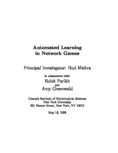
However, to provide such flexibility, the IPsec protocol set is fairly complex, and the chances that a product will be misconfigured—or that several devices will be configured in inconsistent ways—are high. Even with good products, the way they are used can compromise the security it is capable of providing. Many organizations will set up their IPsec infrastructure too quickly, getting it wrong, an anxiety also expressed by Ferguson and Schneier [6], who detail several ways in which misconfigurations could compromise security. The IPsec protocols specify headers and processing that can be used to ensure that packet payloads are encrypted during some portion of their trajectories. They also allow packets to be accompanied by a message authentication code (mac) for part of the trajectory, enabling a recipient to determine the point in the network at which this mac was applied, and making any subsequent alterations detectable. We abstract from the actual state of the packet payload or mac, and simply regard associated IPsec headers as representing the securityrelevant state of the packet. IPsec operations may be applied repeatedly at different points on the network. All decisions are made locally about when to add encryption or macs. Likewise, payload decryption and verifying macs when removing them are local operations. This presents us with another problem of localization: to determine what meaningful global security properties are achieved by some set of local IPsec operations. An example of the difficulty of localization can be seen in Figure 3. Assume that companies A and B each have their own connection to the Internet, with IPsec gateways at the perimeters. Further assume that the two engineering divisions, EngA and EngB have a direct connection to a collaborative testing network, PrivNet. There are likely several different granularities of security policy being implemented: a company-wide policy dictating what traffic should leave the company in an IPsec tunnel; a financial policy about what traffic should leave SG1 unencrypted; an engineering policy about what sorts of traffic should be allowed in the PrivNet area and with what protection; and so on. It is clear that these localized policies can affect one another, and we desire a way 16
to determine in what ways they actually do. In [10], we formalized the types of security goal that IPsec is capable of achieving. We then provided criteria that entail that a particular network achieves its IPsec security goals. We present this work here as an example of rigorous automated security management. Before presenting our network model (Section 3.2) and defining the security properties of interest to us here (Section 3.3), we present a brief introduction to the IPsec protocols (Section 3.1). In Section 3.4, we develop algorithms for checking whether security goals are met, and we prove that the algorithms are correct. The problem is more demanding than the algorithms of Section 2.3, so we have given the correctness proofs in much more detail. In Section 3.5, we describe the configuration-checking software we developed to automate this procedure.
3.1
IP Security
IPsec is a set of Internet standards-track protocols designed to provide high quality, IP layer security services for IPV4 and IPV6. These services include connectionless integrity and data origin authentication (hereafter referred to jointly as authentication), rejection of replayed packets, confidentiality, and limited traffic flow confidentiality, and can be used by any higher level protocol [14, 12, 13]. IPsec processing can be done either within a host or else at a security gateway. In an entirely host-based environment, each individual machine would handle its own IPsec processing, applying cryptographic transforms (and the IPsec headers describing them) before emitting packets onto the network. For incoming packets, IPsec processing requires undoing cryptographic operations, checking the results, and deleting the corresponding IPsec headers on packets received off the network. IPsec processing can also dictate that certain packets without cryptographic processing be passed or dropped. In a host-based implementation, this typically requires changes to the IP stack executing in each host’s kernel. Alternately, one can deploy a smaller number of IPsec enabled gateways, each of which performs IPsec processing on behalf of the machines “behind” it. This end-to-end, network level protection makes IPsec a good protocol for Virtual Private Networks (VPNs), and many current VPNs conform to the IPsec standards. Keys may be manually placed, or alternatively key exchange may be handled by the Internet Key Exchange, a protocol designed for use with IPsec [11]. In this case, there are supplementary needs, including a certain amount of public key infrastructure. In our discussion in this paper, we will not discuss key management further, but will assume that it is handled by some secure means. IPsec processing for outbound packets consists of the following elements. First, a Security Association (SA) is selected based on properties of the existing IP and transport layer headers of the packet. The SA specifies the type of protection, including what cryptographic operations are to be performed, together with parameters including the key. Encryption and cryptographic hashes are 17
used to produce a new payload or a test for integrity (respectively) to achieve confidentiality or authenticated integrity. SAs can be combined into bundles for composite protection. Second, the processsing specified in the SA (or sequence of SAs making up the bundle) is applied. Third, IPsec header information is added to the resulting ciphertext or the hash. The IPsec standard defines two security protocols for traffic protection: Authenticated Header, or AH, and the Encapsulating Security Payload, or ESP. AH provides, as one would expect, authentication services, and some protection against replay attacks. ESP provides confidentiality and limited traffic flow confidentiality; it may be configured to provide authentication with data integrity as well. There are some fine points: AH ensures the integrity of certain header fields that ESP does not cover, even when ESP is used with authentication. Also ESP may be used to provide authentication without encryption. We will assume that when encryption is used, authentication services are also used, because this is advisable [2], and because it is hard to see the real meaning of providing confidentiality for data that may change without notice. What’s the secret then? The security protocols can be used in one of two modes: tunnel and transport. In transport mode, the IPsec header fields are combined with the original IP headers of the packet. This mode can therefore be used only if the entities performing IPsec processing at both endpoints of the communication are the same as the entities communicating. If either end is a security gateway, tunnel mode must be used instead. In tunnel mode, the entire IP packet is protected; a new IP header is created with a new source field and a new destination field. These fields give the addresses of the entry point and the exit point of the tunnel. We focus on IPsec in networks where at least some of the IPsec processing occurs at security gateways. The reasons for this are as follows: • Most networks relying on IPsec do involve security gateways. • Firewalls typically already exist at strategic locations for IP security gateways, and in fact many products provide both firewall functionality and IPsec processing. • Gateways have the advantage that an organization can define an organizationwide security policy; the lion’s share of the enforcement of this policy may be carried out using a limited amount of equipment directly under the management of the organization. Sub-organizations (or individual users on particular hosts) may be completely unaware of this policy, assuming that they do not use IPsec on their own. If they desire to use IPsec, then there are constraints that they must follow to ensure that their processing is compatible with the organization-wide policy; these constraints are described in Section 3.4. Thus, while our model allows for indvidual hosts to be IPsec-enabled, our primary interest lies in the case where this is not the exclusive form of IPsec. In this situation, there are things that can certainly go wrong. For instance, suppose that we want packets from a particular peer s to be authenticated 18
when they arrive at a destination d, and in fact there is a pair of gateways offering IPsec processing between them. There are still ways that packets not originating at s can reach d. For instance, suppose that a spoofer can route packets to d without traversing the gateways. Or suppose the spoofer can route a packet to s’s gateway that arrives on the same interface that traffic from s traverses. To achieve this, the spoofer may even be able to send IPsec-protected traffic to a security gateway near s, where the protected packets claim to be from s but are not. When s wants to ensure confidentiality for packets to d, there are dual concerns. Possibly the packet may be misrouted onto a public network without traversing a gateway. Or possibly a gateway will provide ESP protection, but transmit it to a gateway distant from d, so its contents will be disclosed before it reaches d. We seek a systematic way to express these sorts of problems, and to ensure that they do not occur.
3.2
Modeling
We view systems as composed of areas and devices capable of IPsec operations or packet filtering. A device has interfaces on one or more areas. Any machine (such as a switch or host) that performs no IPsec operations or filtering we may simply ignore. In the example shown in Figure 3, areas appear as ovals and devices appear as black squares. An edge represents the interfaces between a device and the area to which it is connected. We will never connect two areas directly via an edge; this would not give a security enforcement point to control the flow of packets between them. Instead, we coagulate any areas that are connected by a device that provides no security enforcement, representing them by the same oval. While this simple, bipartite graph representation is useful heuristically, it is inconvenient for rigorous modeling of IPsec processing. Several steps of processing may need to occur while the packet is associated with a particular interface, and they may depend as well on the direction in which the packet is traversing that interface. Therefore we prefer a system model in which there are two nodes corresponding to each interface. They represent the conceptual location of a packet when IPsec processing is occurring, either as it traverses the interface inbound into the device or as it traverses the interface outbound from the device. We call these conceptual locations directed interfaces. To incorporate this notion, we will now introduce an enriched system model consisting of a directed graph containing three kinds of nodes. These represent areas, devices, and directed interfaces. To construct a model from a system representation in the style of Figure 3, for each edge between a device d and an area a we insert two directed interface nodes, which we will call id [a] and od [a]. These represent inbound processing for a packet traveling from a to d and outbound processing for a packet traveling from d to a respectively. We add four directed arcs:
19
� � A1 � � @ @ @ @ � � A1 � �
� � I � �
� � B1 � � @ @ @� � @ B2 � �
Figure 4: Unenriched System Representation � � A1 � @ � Rt I @ @ @t J t -� kJ Q ^ � * � Q I Y H t� � * H � t�
� � t � � A2 � �
� � B1 � � t �
t � -t
3 �� H j � H � H t � � � � JYH t J ^t I @ @ � @ � R @ B2 � �
Figure 5: Enriched System Representation
1. a → id [a] and id [a] → d, the inbound arcs, and 2. d → od [a] and od [a] → a, the outbound arcs. For instance, the result of applying this process to the system representation shown in Figure 4 produces the enriched model shown in Figure 5. We will assume an enriched system representation G = (V, E) throughout the remainder of this section. A location ℓ is a member of V ; that is, an area, a device, or an interface. Let P be a set of values we call protocol data. We may think of its values as the elements of IP headers other than source and destination. For instance, an IP header may specify that the protocol is TCP, and the embedded TCP header may specify a particular source port and destination port; this combination of protocol and port information may be taken as a typical member of P . Let A ⊂ P be a set we call authenticated protocol data; it represents those headers that provide IPsec authentication services. Let C ⊂ A be a set we call confidentiality protocol data; it represents those headers that provide IPsec confidentiality services. The assumption C ⊂ A codifies our decision not to consider ESP headers that provide only confidentiality (cf. Sections 3.1; we 20
amplify the point in 3.3.2). A header is a member of the set H = V × V × P , consisting of a source location, a destination location, and a protocol data value. Packet states are members of H ∗ , that is, possibly empty sequences hh1 , . . . , hn i. We use · as prefixing operator: h · hh1 , . . . , hn i = hh, h1 , . . . , hn i. Let K be a set of “processing states,” with a distinguished element ready ∈ K. Intuitively, when an interface has taken all of the processing steps in the Security Association (SA, see 3.1) for a packet p, then it enters the processing state ready, indicating that the packet is now ready to move across the arc from that interface. If this is an outbound interface, it means that the packet may now go out onto the attached area; if it is an inbound interface it means that the packet may now enter the device, whether to be routed to some outbound interface or for local delivery. Other members of K are used to keep track of multistep IPsec processing, when several header layers must be added or removed before processing is complete at a particular interface. These clusters of behavior represent IPsec Security Association bundles. We regard the travels of a packet through a system as the evolution of a state machine. The packet may not yet have started to travel; this is the start state. The packet may no longer be traveling; this is the finished state. Every other state is a triple of a node ℓ ∈ V , indicating where the packet currently is situated; a processing state κ ∈ K, indicating whether the packet is ready to move, or how much additional processing remains; and a packet state θ ∈ H ∗ , indicating the sequence of headers nested around the payload of the packet. Definition 1 Ω(G, K, P, A, C) is the set of network states over the graph G = (V, E), the processing states K, and the protocol data P with C ⊂ A ⊂ P . Let H = V × V × P . Ω(G, K, P, A, C) is the disjoint union of 1. start, 2. stop, and 3. the triples (ℓ, κ, θ), for ℓ ∈ V , κ ∈ K, and θ ∈ H ∗ . The transition relation of a network state machine is a union of the following parameterized partial functions. We define what the resulting state is, assuming that the function is defined for the state given. We also constrain when some of these functions may be defined. Different IPsec security postures are determined by different choices of domain for each of these partial functions (subject to the constraints given). The sets of authenticated headers A and confidentiality headers C play no role in determining the evolution of network states, but they play a central role in expressing and verifying the security goals for IPsec, as formulated in Section 3.3. Definition 2 A network operation is any partial function of one of the following forms:
21
1. Packet creation operators createℓ,h (start) = (ℓ, ready, hhi), when defined, for (ℓ, h) ∈ V × H. createℓ,h is not defined unless its argument is the state start. 2. The packet discard operator discard(ℓ, κ, θ) = stop, when defined. discard is undefined for start. 3. Packet movement operators movee,κ (ℓ, ready, θ) = (ℓ′ , κ, θ), when e ∈ E, e ℓ → ℓ′ and κ 6= ready. movee,κ is undefined for all other network states. 4. Header prefixing operators prefixh,κ (ℓ, κ′ , θ) = (ℓ, κ, h · θ) when defined. The function prefixh,κ is nowhere defined when h 6∈ A. 5. Header pop operators popκ (ℓ, κ′ , h · θ) = (ℓ, κ, θ) when defined. 6. Null operators nullκ (ℓ, κ′ , θ) = (ℓ, κ, θ) when defined. A transition relation → ⊂ (Ω(G, K, P, A, C) × Ω(G, K, P, A, C)) is a union of operators create, discard, move, prefix, pop, and null. When → is a transition relation for Ω(G, K, P, A, C), we regard each history of the associated state machine as representing a possible trajectory for a packet through the network. The assumption that prefixh,κ is nowhere defined when h 6∈ A means that the only nested headers we consider are IPsec headers. The discard operator allows us to subsume packet filtering, as in Section 2, as part of IPsec functionality, which matches the intent of the IPsec RFC [14]. We call the assumption that movee,κ′ (ℓ, κ, θ) = (ℓ′ , κ′ , θ) is not defined when κ 6= ready the motion restriction. We call the assumption that it is not defined when κ′ = ready the inbound motion restriction. The motion restriction codifies the assumption that a device will not move a packet until it is ready. The inbound motion restriction codifies the assumption that there will always be a chance to process a packet when it arrives at a location, if needed, before it is declared ready to move to the next location. Given a packet p, we call the address in the source header field of its topmost header src(p). We call the address in the destination header field of the topmost header dst(p). We also call a packet p an IPsec packet if its outermost header h is in A. We say that a header h provides confidentiality if h ∈ C, and that it provides only authentication if h ∈ A \ C. Our treatment need not distinguish between ESP used only for authentication and AH; however, these headers may be different members of A, and individual systems may have security goals requiring one rather than the other. Cryptographic Assumptions We will make two assumptions about the IPsec cryptographic headers. First, we assume that cryptographic headers cannot be spoofed; in other words, that if we receive a message with an authenticating header from a source “known to us,”1 then the entity named in the 1 Presumably as certified by some public key infrastructure, and certainly assumed to include those devices which are shown as nodes in the system model.
22
source field of the header is the entity that applied the header, and the payload cannot have been changed without detection. Second, confidentiality headers have the property that packets protected with them can be decrypted only by the intended recipient, i.e. the device named in the ESP header destination field. More formally, using a dash for fields that may take any value, we stipulate that for any transition: (ℓ, κ, h[s′ , d′ , −], . . .i) −→ (ℓ, κ′ , h[s, d, α], [s′ , d′ , −], . . .i) α ∈ A and s ∈ S implies ℓ = s. Moreover, for any transition: (ℓ, κ′ , h[s, d, γ], [s′ , d′ , −], . . .i) −→ (ℓ, κ, h[s′ , d′ , −], . . .i) γ ∈ C and s ∈ S implies ℓ = d. These properties axiomatize what is relevant to our analysis in the assumption that key material is secret. If keys are compromised then security goals dependent on them are unenforceable.
3.3
Expressing Security Goals
We focus on authentication and confidentiality as security goals in our analysis. Concrete security goals select certain packets that should receive protection [14]; selection criteria may use source or destination addresses, protocol, and other header components such as the ports, in case the protocol is TCP or UDP. 3.3.1
Authentication Goals
The essence of authentication is that it allows the recipient to—so to speak— take a packet at face value. Thus, for a packet p selected for protection by an authentication goal, If A is the value in the source header field of p as received by B, then p actually originated at A in the past, and the payload has not been altered since. We do not regard a packet as being (properly) received unless the cryptographic hash it contains matches the value computed from a secret shared between the two IPsec processing devices and the packet contents. It will not be delivered up the stack otherwise, nor forwarded to another system after IPsec processing. 3.3.2
Confidentiality Goals
We assume that confidentiality headers (as in ESP 3.1) provide authentication, and add encryption. We have two reasons for doing so. First, the IPsec specification allows both authentication and confidentiality to be used with the ESP header; it is inadvisable to request only confidentiality when authentication can also be had at the same time, and at modest additional processing cost. Second, it seems hard to state precisely what data is kept confidential, if that data might 23
change as the packet traverses the network [2, 6]. When using confidentiality headers, we are therefore attempting to achieve an authentication goal as well as a confidentiality goal. A confidentiality goal for a packet with source field A, requiring protection from disclosure in some network location C, stipulates: If a packet originates at A, and later reaches the location C, then while it is at C it has a header providing confidentiality. The cryptographic protection may refer to the ESP header more specifically, stipulating certain parameters (key length, algorithm, etc). The proviso that the packet was once at A is necessary, because in most cases we cannot prevent someone at C from creating a spoofed packet with given header fields. However, a spoofed packet cannot compromise the confidentiality of A’s data if it has no causal connection to A. 3.3.3
Example Goals
Consider the network in Figure 3. Given this example network, a potential authentication goal could be that packets traveling from EngA to EngB should be authenticated, meaning that any packet with source field claiming to be from EngA that reaches EngB should in fact have originated in EngA. An example confidentiality goal is that packets traveling from FinA to FinB should be encrypted whenever outside those areas. This means that if a packet has source field in FinA, and actually originated there, then if it reaches any other area R, it has an ESP header providing encryption while at R. One advantage to this form of expression is that it is semantically precise. Another is that policies expressed in this form appear to be intrinsically composable, in the sense that separate goals can always be satisfied together. Moreover, this form of expression often suggests placement of trust sets, in a sense we will now introduce. 3.3.4
Trust Sets
Once a packet enters an appropriate cryptographic tunnel, achieving a security goal does not depend on what happens until it exits. Thus, the set of locations in the network topology that are accessible to the packet from the source (before entering the tunnel) or accessible from the exit of the tunnel (before reaching the destination) are the only ones of real importance. We will call these locations a trust set for a particular security goal. A trust set is goal-specific; different goals may have different trust sets. For instance, an engineering group working on a sensitive project could easily have much more restrictive security goals than its parent corporation (in terms of trust). Typically, a trust set is not a connected portion of the network, but often instead consists of two large portions (each a connected subgraph), with a large, less trusted network between them, such as the public Internet. In some cases the trust set may consist of several islands, and the tunnels may not connect 24
all of them directly. In this case, a packet may need to traverse several tunnels successively in order to get from one island of the trust set to a distant one. The choice of trust set for a particular security goal is a matter of balance. Clearly, the source must belong to the same island of the trust set as the tunnel entrance, and the tunnel exit must belong to the same island as the destination (or the entrance to the next tunnel). This encourages creating trust sets as large as possible, since then a few tunnels may serve for many endpoints. However, the scope of a trust set must generally be limited to a set of areas on which it is possible to monitor traffic and check configurations. This encourages making the trust sets as small as possible. The art of using IPsec effectively consists partly in balancing these two contrasting tendencies. Boundaries Of special importance are those systems inside a trust set with a direct connection to systems outside the trust set. We term these systems the boundary of the trust set. We assume that every device on the boundary of a trust set is capable of filtering packets. This may be a portion of its IPsec functionality [14]. Alternatively, the device may not be IPsec-enabled, but instead be a filtering router or packet-filtering firewall. We regard such devices as a degenerate case of an IPsec-enabled device, one which happens never to be configured to apply any cryptographic operations. Definition 3 A trust set S for G = (V, E) consists of a set R ⊂ V of areas, together with all devices d adjacent to areas in R and all interfaces id [∗] and od [∗]. The inbound boundary of S, written ∂ in S is the set of all interfaces id [a] or id [d′ ] where d ∈ S and a, d′ 6∈ S. The outbound boundary of S, written ∂ out S is the set of all interfaces od [a] or od [d′ ] where d ∈ S and a, d′ 6∈ S. Suppose that, in Figure 5, a security goal states that packets traveling between Ai and Bj (i, j ∈ {1, 2}) must be protected with a confidentiality header whenever in the Internet area. A reasonable trust set S for this goal would include all areas except for the Internet, as well as their attached devices and interfaces. The trust set S is not a connected set. The outbound boundary of S is labeled in Figure 6, and the inbound boundary in Figure 7.
3.4
Deriving Algorithms
Given an environment in which one can rigorously reason about packet states, and precise specifications of security goals, how does one ensure the goals are enforced? This section focuses on answering that question, by detailing formal behavior requirements for systems and then proving they guarantee enforceability. In our reasoning, we will assume that security goals are stated in the form given in Sections 3.3.1 and 3.3.2.
25
� � A1 � @ � Rt I @ @ @t J d -� kJ Q ^ � * � Q I Y H t� � * H � t�
� � t � � A2 � �
� � B1 � � t � t
� -t
3 �� H j � H � H � d� � � JYH t J ^t I @ @ � @ � R @ B2 � �
Figure 6: Outbound boundary marked with hollow circles ◦
� � A1 � @ � Rt I @ @ @t J -� kJ Q ^ � *t � Q I Y H d� � * H � t�
� � t � � A2 � �
� � B1 � � t �
t � -d
3 �� H j � H � H � t � � � JYH t J ^t I @ @ � @ � R @ B2 � �
Figure 7: Inbound boundary marked with hollow circles ◦
26
3.4.1
Authentication
Our authentication problem can be stated in the following way. Suppose a and b are area nodes. What processing conditions can we impose such that an authentication goal holds? To make this precise, let us say an authenticated state is one having the form (a, κ, h[a, −, −]i) and an acceptor state is one of the form (b, ready, h[a, −, −]i). The symbol authentic denotes the set of authenticated states, accept denotes the set of acceptor states. We want to ensure that every acceptor state, in which a packet purportedly from a is delivered at b, is preceded by an authenticated state, in which it was sent from a. Our question can be stated thus: exhibit a set of processing restrictions which ensure the following: For any path start −→∗ ω where ω ∈ accept there is an intermediate state ω ′ such that start −→∗ ω ′ −→∗ ω where ω ′ ∈ authentic. Thus, whenever an acceptor state is reached, an authenticated state must have occurred earlier in the state history. In this sense, the prior occurrence of an authenticated state is guaranteed when an acceptor state is observed. This use of “authenticated” for the states ω ′ ∈ authentic follows Schneider [22]. Achieving authentication requires two types of behavior restrictions on trust set nodes, depending on whether or not the system in question is in a boundary. We list behavior restrictions for each. First we list a constraint that is required for the proofs, but is vacuous (trivially satisfied) in IPsec [14], where inbound processing can only remove packet headers, but never add them. Fix a trust set S. Prefix Ready Rule. (ℓ, κ, θ) −→ (ℓ, κ′ , h · θ) If ℓ ∈ ∂ in S then κ = ready. Authentication Tunnel Constraints In order to achieve authentication, there are two rules that must be observed by every IPsec-enabled device in the trust set. The first of these is that nodes in S must not spoof packets with sources in S. Creation Rule. For any transition start −→ (ℓ, κ, h[s, −, −]i) if ℓ ∈ S then ℓ = s. For the second rule, fix a trust set S. Whenever an IPsec-enabled device in S processes an IPsec packet p with src(p) 6∈ S, and removing this header leads to a packet p′ with src(p′ ) ∈ S, p′ must be discarded. It codifies the idea that only nodes in S should be trusted to certify a packet as coming from S. 27
Pop Rule. For any transition (ℓ, κ, h[s, d, A], [a, −, −]i) −→ (ℓ, κ′ , h[a, −, −]i) If ℓ ∈ S then s ∈ S. Authentication Boundary Constraints Given the authentication goal above, boundary systems must only abide by one extra processing constraint: they must not pass an inbound packet that did not present any authentication headers. Inbound Ready Rule. (ℓ, κ, θ) −→ (ℓ, ready, h[a, −, −]i) If κ 6= ready and ℓ ∈ ∂ in S, then θ = h[s, d, A], [a, −, −]i. 3.4.2
Unwinding
We prove that the processing restrictions formulated above are sufficient to ensure the authentication goal. To do so, we exhibit an unwinding set G. Definition 4 An unwinding set G is a set such that 1. start 6∈ G, 2. accept ⊆ G, 3. authentic ⊆ G, 4. For any transition x → y with x 6∈ G and y ∈ G then y ∈ authentic. Proposition 1 A sufficient condition for the authentication condition to hold is the existence of an unwinding set. Proof. Any path start −→∗ ω with ω ∈ accept, must have the form start −→∗ x → y −→∗ ω with x 6∈ G, y ∈ G. By the unwinding condition 4, y ∈ authentic.
�
A transition x → y is header non-augmenting iff it is of the form (ℓ, κ, θ⌢ θ′ ) → (ℓ, κ′ , θ′ ), where θ′ is a final segment of the concatenation θ⌢ θ′ . We now exhibit an unwinding set G. G = accept ∪ authentic ∪ continue where continue is defined: Definition 5 (Continuing States) A state is a continuing state if it belongs to one of the three disjoint classes below: 28
C1 (ℓ, ready, h[a, −, −]i) for ℓ ∈ ∂ in S; C2 (ℓ, κ, h[a, −, −]i) for ℓ ∈ S \ ∂ in S, i.e. for locations in the portion of S other than the inbound boundary; C3 (ℓ, κ, h· · · [s, d, A], [a, −, −]i) for s ∈ S and any ℓ. Proposition 2 G is an unwinding set. Proof. Suppose x → y with x 6∈ G, y ∈ G. The proof is a completely mechanical enumeration of cases. In each case, we show either that either it cannot really occur or that y ∈ authentic. Case I: y ∈ accept.
By definition of accept, y is of the form (b, ready, h[a, −, −]i).
1. b ∈ ∂ in S. (a) x → y is a motion. The inbound motion restriction excludes this case. (b) x → y is non-augmenting. By the inbound ready rule, x is of the form (b, κ, h. . . , [s, d, A], [a, −, −]i) with s ∈ S. This implies x ∈ C3 ⊆ continue ⊆ G. (c) x = start. In this case, by the creation rule b = a. Thus y ∈ authentic. 2. b ∈ S \ ∂ in S. (a) If x → y is a motion, then x must be of the form (ℓ, ready, h[a, −, −]i) By definition of network boundary of S, ℓ ∈ S. This implies x ∈ C1 ∪ C2 ⊆ G. This case is thus excluded. (b) Otherwise x must be of one the forms i. (b, κ, h[s, d, A], [a, −, −]i) with s ∈ S, so x ∈ C2 ⊆ G, which excludes this case also. ii. start. In this case, by the creation rule y is of the form (b, κ, h[s, −, −]i) with b = s = a. Thus y ∈ authentic. Case II: y ∈ C1. Thus y = (ℓ, ready, h[a, −, −]i) for ℓ ∈ ∂ in S. 1. x = (ℓ′ , κ, θ). The inbound motion rule excludes this case. 2. x = (ℓ, κ, θ). By the inbound ready rule, the transition x → y must be a pop. In this case, by the pop rule x must be of the form (ℓ, κ′ , h[s, d, A], [a, −, −]i) for s ∈ S, so x ∈ C3 ⊆ G, which excludes this case also. 3. x = start. In this case, the creation rule implies ℓ = a, so y ∈ authentic.
29
Case III: y ∈ C2.
In this case y is of the form (ℓ, κ, h[a, −, −]i) for ℓ ∈ S\∂ in S.
1. x = (ℓ′ , κ′ , θ) with ℓ′ 6= ℓ. In this case, the transition x → y must be a location change. By definition of border, ℓ′ ∈ S and by the motion ready restriction, κ′ = ready. In this case x ∈ C1 or x ∈ C2 depending on whether ℓ′ ∈ ∂ in S or ℓ′ ∈ S \ ∂ in S. Thus this case is excluded. 2. x = (ℓ, κ′ , θ). In this case, the transition x → y must be a pop. By the pop rule x must be of the form (ℓ, κ′ , h[s, d, A], [a, −, −]i) for s ∈ S, so x ∈ C3 ⊆ G, which excludes this case also. 3. x = start. In this case, the creation rule implies ℓ = a, so y ∈ authentic. Case IV: y ∈ C3. y is of the form (ℓ, κ, h· · · [s, d, A], [a, −, −]i) for s ∈ S. 1. If x → y is a motion, then x ∈ C3 2. If x → y is a non-augmenting header transition, then x must also be of the form C3. 3. If x → y is a push, then either x ∈ C3 or x is of the form (ℓ, κ′ , h[a, −, −]i). By cryptographic restriction, ℓ = s ∈ S. In this case x ∈ C1 or x ∈ C2 depending on wehether ℓ ∈ ∂ in S or ℓ ∈ S \ ∂ in S. Thus this case is excluded. � 3.4.3
Confidentiality
We will consider the following confidentiality problem: Suppose a and b are area nodes. What conditions can we impose on the enclave nodes’ processing to ensure that packets traveling from a to b are encrypted whenever they are not in the trust set S? More formally, given some set of processing restrictions, If we start with a packet of the form (a, ready, h[a, b, p]i), where a, b ∈ S, then it will never be the case that (ℓ, κ, h[a, b, p]i) if ℓ 6∈ S. Achieving confidentiality is more simple than authentication. There are two simple constraints, one on all devices in the trust set, and an additional constraint for boundary members. Confidentiality Tunnel Constraints Fix a trust set S. The constraint on all trust set members requires them not to “tunnel” packets requiring protection out to a dangerous area. Our constraint will ensure that whenever a system inside S adds a confidentiality header to a packet which would require protection, the source and destination of the added header are also in S. Push Rule. For any transition (ℓ, κ, h[s1 , d1 , p1 ] · · · [a, b, p]i) −→ (ℓ, κ′ , h[s2 , d2 , p2 ][s1 , d1 , p1 ] · · · [a, b, p]i) if ℓ ∈ S, s1 , d1 ∈ S, and p1 6∈ C, then s2 , d2 ∈ S. We include the case where h[s1 , d1 , p1 ] · · · [a, b, p]i = h[a, b, p]i. 30
Confidentiality Boundary Constraints As with authentication, we impose one constraint on boundary members. If a packet p is traversing an outbound interface on the boundary of S, and p could contain a packet p0 ∈ P with no confidentiality header, discard p. One way to safely implement this is to pass a packet p only if its topmost layer is a confidentiality header, or else it has no IPsec headers and p 6∈ P . Outbound Ready Rule. For any transition (ℓ, κ, θ) −→ (ℓ, ready, θ′ ) if ℓ ∈ ∂ out S, then either θ′ = h[s, d, C], . . . [a, b, p]i for s, d ∈ S, or else θ′ = h[s′ , d′ , −], . . .i where either s′ or d′ not in S. Invariant. We will prove that the processing restrictions formulated above are sufficient to ensure the confidentiality goal using an invariant of our state machine. We will first show that the invariant holds, then prove that given the invariant, our confidentiality goal holds as well. Proposition 3 Suppose that Σ is a state machine satisfying the outbound ready rule and the Push rule, and suppose that (ℓ, κ, θ) is the state resulting from a sequence of actions beginning with createa,[a,b,p] , where a, b ∈ S. 1. If ℓ ∈ S, then either (a) whenever [s1 , d1 , p1 ] is any layer of θ, then s1 , d1 ∈ S and p1 6∈ C, or (b) there is a final segment of θ of the form h[sk , dk , C] · · · [si , di , pi ] · · ·i where sk , dk ∈ S and for each i < k, si , di ∈ S and pi 6∈ C. 2. If ℓ 6∈ S, then there is a final segment of θ of the form h[sk , dk , C] · · · [si , di , pi ] · · ·i where sk , dk ∈ S and for each i < k, si , di ∈ S and pi 6∈ C. Proof. We will examine each of the possible state transitions in turn, showing for each that they cannot violate the invariant. Case 1: create and discard In the case of the create operator, we know that the first transition in our state machine is the following (which does not violate the invariant): start −→ (a, ready, h[a, b, p]i) The invariant imposes no constraints on the finish state, thus the discard transition is irrelevant. Case 2: pop Assume that we are at location ℓ. We are interested in the state transition popκ (ℓ, κ′ , h · θ) = (ℓ, κ, θ). Our cryptographic assumptions prevent any location from removing an encryption layer not destined for them. Thus, no location can remove the necessary confidentiality protection (provided it was applied), and the invariant is not violated. 31
Case 3: prefix Assume once again we are at location ℓ. The transition is prefixh,κ (ℓ, κ′ , θ) = (ℓ, κ, h · θ). The only case which has bearing on the invariant is that where ℓ ∈ S, and there is no encryption layer in θ. By the Push rule, src(h), dst(h) ∈ S as well. If h is a confidentiality header, the packet now satisfies the second invariant condition for locations in S. If h is not a confidentiality header, the packet satisfies the first invariant condition for locations in S. Case 4: null Case 5: move
The invariant imposes no constraints on κ. Again, assume we are at location ℓ. The transition is movee,κ (ℓ, ready, θ) = (ℓ′ , κ, θ)
Since this involves no change of state, the only case which could violate the invariant is that where ℓ ∈ ∂ o S and ℓ′ 6∈ S. The Outbound Ready rule ensures that the top layer of θ is either [s, d, C] with s, d ∈ S or [s′ , d′ , −] with s′ , d′ 6∈ S. The Push rule ensures that below the bottom-most confidentiality layer, all layers have source and destination in S. So, regardless of which portion of the Outbound Ready rule is appropriate, the invariant is not violated. Thus, the given invariant holds for our state machine. We now must show it implies enforcement of the confidentiality goal. The confidentiality goal is ensured if it is never the case that (ℓ, κ, h[a, b, p]i) if ℓ 6∈ S. Condition 2 of the invariant provides this: suppose that we’re at ℓ 6∈ S. Then there is at least one layer [s, d, C] with s, d ∈ S, and no layers with external sources ‘beneath’ that layer. � 3.4.4
Manageability
On of the advantages of our treatment of IPsec is that it is compatible with the layered structure of organizations. In particular, the two corporations A and B in Figure 3 may have security goals they want to achieve via IPsec, while the two engineering departments within them may have more tightly constrained goals that they need to achieve. In this case, they may manage their own IPsec capable equipment and configure them as needed. Typically such suborganizations do not have access to the topological boundary of the parent organizations. In this case, to be sure that their IPsec configurations do not interfere with the goals of their parents, they need only ensure that they obey two conditions, namely the Pop Rule and the Push Rule for trust sets S in which that the parent participates.
3.5
Implementation: The Confidentiality and Authentication IPsec Checker (CAIC)
Checks for these behavior restrictions were implemented in the “Confidentiality and Authentication IPsec Checker” (or CAIC, pronounced “cake”). When given Cisco IPsec configuration files and a network / policy specification, CAIC 32
will check trust sets and boundaries for the behavior restrictions described above. It returns to the user both a verdict (the goal is enforced or not) and a description of goal failure (if appropriate). It describes which behavior restriction was not met, and the specific sorts of packets upon which the goal fails. 3.5.1
CAIC Input
As mentioned above, CAIC checks security goal enforcement for a network topology that uses Cisco routers for IPsec processing. It requires information about router configuration, network topology (including trust set and boundary information), and security goal information as input. This information is expected in a single file, though router configuration files can be referenced in the following way (lines beginning with an exclamation point are comments): ! configurations begin routers SG1 SG2 SG5 ... end routers
of all IPSec-enabled devices in the trust set testconfigs1/CRCF.SG1.txt ios testconfigs1/CRCF.SG2.txt ios testconfigs1/CRCF.encr-SG5.txt ios
The first field in a router specification is a unique name given to the router (for example, SG1 in Figure 3). The second field identifies the router’s configuration information (this information can be gotten by running the command show running-config on a Cisco router). The third field indicates the type of router configuration; currently, the tool only supports Cisco routers running IOS. Expansion of the tool to support other types of router is ongoing, however. CAIC can be used in an iterative manner, to see how changing configurations affect goal achievement. This file format allows all router configuration files could be located in some central location, and referenced by path. After router specification, trust sets are defined. A particular trust set is delimited with begin trustset .... end trustset and trust set members are given via IP address ranges and masks. One can imagine that the areas EngA and PerimA in Figure 3 might have the following ranges: 199.94.88.0 199.94.89.0
0.0.0.255 trust 0.0.0.255 trust
!ENG A !PERIM A
Boundary information is also crucial; after trust sets are defined, certain hosts are called out to be boundary elements. An example boundary member specification is as follows: D1
Serial
0
! 199.94.55.254 D1 & internet
33
This line states that on IPsec device D1, the serial 0 interface is a boundary interface. (The location of the device, and its IP address, are given in the comment.) After trust sets and boundaries are specified, the input file contains goal statements. There are two kinds of goal statement, authentication and confidentiality. CAIC supports Cisco-style definition of packet sets which can later be referenced in goals. The following small access list defines packets between areas FinA and PayrollB for some company: !FIN A & Payroll B A B access-list 191 permit ip 199.94.87.0 0.0.0.255 199.94.92.0 0.0.0.255 access-list 191 permit ip 199.94.92.0 0.0.0.255 199.94.87.0 0.0.0.255 The packet set 191 can later be referenced in any security goal statements in the input file. A simple example desires confidentiality for the packets described by the above access list: ! ACHIEVEMENT 191 achieve confidentiality for 191 3.5.2
Goal Enforcement Checking and Output
Given the network information, trust set/boundary information, and security goals for a particular network, CAIC will perform each of the checks described in Section 3.4 for each individual goal. CAIC shares much of its implementation with NPE, and uses Binary Decision Diagrams to represent the packet sets relevant to each network configuration. When a particular security goal is achieved, a report such as the following is printed out: Achievement 2 for packets-of-interest ACL number 182 -- an authentication achievement. In the case that a particular goal is not enforced, additional information is printed after the identification lines above. First, a notification of the specific behavior check which failed is printed, as well as the offending location. An example where a confidentiality Push rule was not obeyed follows: Confidentiality Push Rule NONCOMPLIANCE involving crypto map B1>>cm-cryptomap__1 in interface Serial0 of device testconfigs4/CRCF.B1.txt. The peer IPSec device is not in the trust set or the tunnel has no confidentiality transform. Following the specific rule infraction and its location, a description of the packets of interest is given. CAIC has been tested with reasonably sized network specifications generated with Cisco’s “ConfigMaker” tool. This tool allows a user to graphically specify 34
their network topology, and then produces configuration files based on the input. Using this tool, CAIC was run on networks involving tens of areas and devices, and under ten security goals. On a Pentium II 450 desktop PC with 256MB of RAM, CAIC takes less than 10seconds to return results. CAIC can easily and quickly handle network topologies with hundreds of IPsec-enabled routers, each being analyzed in isolation, and many tens of security goals.
4
Combined Packet Filtering and IPsec
To protect its networks, organizations need to use a variety of different techniques in tandem. Most companies use both packet-filtering firewalls and IPsec, typically as part of a Virtual Private Network. We have presented techniques to use either of these mechanisms separately to ensure that meaningful security goals are achieved, but their use in combination complicates matters. The remaining question is how to ensure that dangerous packets that should have been filtered were not protected by IPsec headers (and possibly encrypted) as they traverse the filtering point where they should be discarded. Later, a security gateway may remove the IPsec headers and cryptographic transformation, unleashing packets that will damage the recipient. Thus, our core idea is that tunnel endpoints must impose all filtering constraints that might have been missed while the packet was encapsulated with IPsec. Following our method for rigorous automated security management, we need to take four steps to resolve this problem. The first, the modeling step, is unnecessary in this case, since the model of Section 3 is already sufficiently expressive. In particular, packet filtering is already expressed as an aspect of IPsec processing as codified in Definition 2. We can adopt the previous model unchanged.
4.1
Expressing Security Goals
The security properties we would like to achieve are essentially the same as in the preceding sections, namely filtering goals, authentication goals, and confidentiality goals. Since authentication and confidentiality goals were already formalized within the same modeling framework in Section 3.3, we leave them unchanged here. The same methods still suffice to ensure that they are met in a particular network configuration. In defining filtering goals, we have additional degrees of freedom. In Section 2.1.4, trajectories associate a single packet with all of the locations traversed. By contrast, in the trajectories formalized as histories of the state machines of Section 3.2, Definitions 1 and 2, the packet may have different sequences of headers while traversing different locations. If we retain the idea from Section 2.2.1 that a filtering policy statement will concern two locations and the packets that can travel from one to the other, then we have a choice how to characterize those packets. Should we consider the state of the packet
35
as they leave the earlier location, as they arrive at the later location, or allow both to vary independently? We choose in fact to consider only trajectories in which the packet has the same headers at the early and later position, which we can call “symmetric twolocation filtering statements.” This decision is motivated by two considerations: • Known attacks do not involve IPsec. That is, a packet with IPsec headers is not known to exercise serious vulnerabilities, for instance in the tcp/ip stack and its processing of IPsec messages. Such vulnerabilities, if discovered, must be corrected very quickly, since it is intolerable to have vulnerabilities within the infrastructure intended to provide security itself.2 Known attacks may be transmitted via packets that, for part of their trajectory, are IPsec-protected; however, they do their harm only when restored to their original form. Thus, we consider that symmetric two-location filtering statements express the practically important security objectives. • An adaptation of the algorithms of Section 2.3 provide good ways of reasoning about symmetric two-location filtering statements. One other decision is also needed, whether to interpret the first location of a two-area symmetric statement as concerning the location at which the packet originates, or simply some location traversed before the other location. We choose to interpret it as the point of origin of the message, a notion that makes sense in a model in which data origin authentication is one of the security services provided. We capture the notion of two-location filtering statements in the following definition. Definition 6 Let Ω(G, K, P, A, C) be a set of network states (Definition 1) and → be a transition relation for it (Definition 2). Let G = (V, E) and H = V × V × P . A symmetric two-location filtering statement is a triple (ℓ, ℓ′ , φ) where ℓ, ℓ′ ∈ V and φ ⊂ H ∗ . Let t be a trajectory, i.e. a history of (Ω, →), so t = hstart, (ℓ1 , κ1 , θ1 ), . . . , (ℓn , κn , θn ), . . .i. The trajectory t is a counterexample to a symmetric two-location filtering statement (ℓ, ℓ′ , φ) if, for any n, ℓ = ℓ1 , ℓ′ = ℓn , and θ1 = θn 6∈ φ. (Ω, →) satisfies ℓ, ℓ′ , φ if no trajectory is a counterexample to it. By the form of the create in Definition 2, we know that θ1 is a packet state of length 1 in the sense that θ1 = hhi for some header h. So we may also assume that φ concerns only packet states of length 1, i.e. θ ∈ φ implies θ = hhi for some header h. 2 Potential denial-of-service attacks using (e.g.) fragmented IPsec packets, requiring cryptographic processing to discover that they should be discarded, are a somewhat different matter, and indeed we have not considered denial-of-service attacks and availability goals in this paper.
36
4.2
Deriving Algorithms
We want now to develop algorithms which given M = (Ω, →) and a filtering statement ℓ, ℓ′ , φ, will definitely tell us in case M does not satisfy ℓ, ℓ′ , φ, and will rarely report failure unless there exists a counterexample to the filtering statement. To do so, we reduce the problem from the enriched graph G of Ω, to an ordinary undirected, bipartite graph G′ to which the NPE algorithms apply. In the process, we will also use the confidentiality and authentication properties known to hold of M to give additional information reducing false positives. That is, the additional information will help reduce the cases in which we report that there may be violations, when in fact there is no counterexample t. For the remainder of this section, fix a network configuration M = (Ω, →). We “reabsorb” the interfaces of a router into the router, and replace each pair of contrary directed edges by a single undirected edge, thus turning a graph having the form shown in Figure 5 into one taking the form shown in Figure 4. If an enriched graph G is reabsorbed in this way, we refer to the result as Gr . IPsec Tunnels More importantly, we create new fictional interfaces between two potentially distant routers to model the IPsec tunnels that may lie between them. In this way, we recognize IPsec as a service that transports packets via a safe medium. We regard these fictional interfaces as filtering points for each of the two routers. One permits outbound (from the router) all those packets that the endpoint pushes IPsec headers onto, and the other permits inbound (into that router) all packets that the router accepts, having popped IPsec headers off them. More precisely, let od [a] be the outgoing interface from device d onto an area a. We say that od [a] is a tunnel entrypoint for d′ if there are any packet states hhi and protocol data p such that od [a] pushes [d, d′ , p] onto hhi, eventually readying [d, d′ , p] · hhi, or the result of further pushes, to move from the interface. We say that an incoming interface id′ [a] is a tunnel exitpoint from d if there are any packets [d, d′ , p] · hhi off which id′ [a] pops [d, d′ , p], eventually readying hhi or the result of further pops to move from the interface. We say that there is a tunnel between od [a] and id′ [a] if the former is a tunnel entrypoint for the latter, and the latter is a tunnel exitpoint for the former. We say that the contents of a tunnel are the set of packet states hhi such that, if hhi reaches od [a], then it readies some · · · · [d, d′ , p] · hhi, and moreover there is some · · · · [d, d′ , p] · hhi which, if it reaches id′ [a], then hhi will be readied by id′ [a]. Given a graph Gr , constructed by reabsorbing an enriched network graph G, we add an interface between d and d′ whenever there is a tunnel between any pair of their interfaces. The device d is assumed to pass outbound over this interface the union of the contents of all tunnels to interfaces of d′ , and d′ is assumed to pass inbound the same set of packet states. In order to make the result formally a bipartite graph, we must also add a fictitious area to which only these two new interfaces are connected. We will refer to the resulting bipartite graph as Grt .
37
Exploiting Authentication and Confidentiality Goals In our original NPE work, we never had a guarantee that the source field of a packet could be trusted. Since IPsec gives us such guarantees, we propose to take advantage of them. Likewise, IPsec also gives us a confidentiality assertion that certain packets, having originated in one location, will always be in encrypted form when traversing another location. We extract, therefore, two families of sets of packet states. For each pair of locations ℓ, ℓ′ , we let αℓ,ℓ′ be the set of h[s, d, p]i such that address s belongs to the area or device ℓ, and M provides authentication services for h[s, d, p]i, as determined for instance by CAIC (Section 3.5). Let γℓ,ℓ′ be the set of packets h[s, d, p]i such that addresss belongs to the area or device ℓ and M provides confidentiality services for h[s, d, p]i, as determined likewise by CAIC. We may now use the same algorithms provided by NPE, though when calculating the packets that may flow from ℓ0 to ℓ1 , we may omit packets in αℓ,ℓ1 for ℓ 6= ℓ0 . These packets cannot reach ℓ1 unless they originate in ℓ, not ℓ0 . Likewise, we may omit packets in γℓ0 ,ℓ1 , as these packets will never be in their original state when they reach ℓ1 , but will necessarily have an IPsec confidentiality header. In this way, we may use the same methods as in NPE, but sharpened to reflect both the transport opportinities created by IPsec and also the authentication and confidentiality assertions that it offers. We have not yet incorporated these methods into a tool such as NPE or CAIC.
5
Conclusion
We have argued by example in favor of rigorous automated network security management. This method emphasizes modeling, which allows a class of systems to be represented in a uniform mathematical style. Configuration files may be parsed to generate a representation of those aspects of an actual system that are required by the modeling. The modeling ensures that a class of practically meaningful security goals may be expressed in terms that fit with the representation. As a consequence, algorithms for checking whether a system meets a security goal may be developed and verified. In some cases, an algorithm can also construct a related system that achieves a goal when the actual system does not. Finally, an implementation allows these algorithms to be applied to a problem instance without the need for any formal modeling expertise at runtime. Several advantages follow from this approach. It is efficient, allowing for the time-consuming task of formal verification to be done only once. Further, this verification can be separate from any property-checking tools, allowing those tools to be implemented quickly, and run efficiently. We illustrated this approach by summarizing previous work on packet-filtering and IPsec formal verification. We also introduced a new instance of this verification approach which ensures achievement of both packet-filtering goals and IPsec desires. Rigorous automated security management appears to be effective for a range
38
of information security problems. We have applied it to analyze policies [9] in an operating system offering Mandatory Access Control, namely Security Enhanced Linux [16, 17].
References [1] Yair Bartal, Alain Mayer, Kobbi Nissim, and Avishai Wool. Firmato: A novel firewall management toolkit. In Proceedings, IEEE Symposium on Security and Privacy. IEEE CS Press, May 1999. [2] Steven Bellovin. Problem areas for the IP security protocols. In Proceedings of the Sixth USENIX UNIX Security Symposium, July 1996. Also at ftp://ftp.research.att.com/dist/smb/badesp.ps. [3] Karl S. Brace, Richard L. Rudell, and Randal E. Bryant. Efficient implementation of a BDD package. In 27th ACM/IEEE Design Automation Conference, pages 40–45, 1990. [4] Randal E. Bryant. Graph-based algorithms for boolean function manipulation. IEEE Transactions on Computers, C-35(8):677–691, August 1986. [5] Cisco Systems, San Jose, CA. Router Products Command Reference, 10th edition, 1994. Chapters 10 to 17 (especially Chapter 16). For more recent information, see http://www.cisco.com/univercd/. [6] Niels Ferguson and Bruce Schneier. A cryptographic evaluation of ipsec. Counterpane Internet Security, Inc., available at http://www.counterpane.com/ipsec.html, 1999. [7] Joshua D. Guttman. Filtering postures: Local enforcement for global policies. In Proceedings, 1997 IEEE Symposium on Security and Privacy, pages 120–29. IEEE Computer Society Press, May 1997. [8] Joshua D. Guttman. Security goals: Packet trajectories and strand spaces. In Roberto Gorrieri and Riccardo Focardi, editors, Foundations of Security Analysis and Design, volume 2171 of LNCS. Springer Verlag, 2001. [9] Joshua D. Guttman, Amy L. Herzog, and John D. Ramsdell. Information flow in operating systems: Eager formal methods. Submitted for publication, January 2003. [10] Joshua D. Guttman, Amy L. Herzog, and F. Javier Thayer. Authentication and confidentiality via IPsec. In D. Gollman, editor, ESORICS 2000: European Symposium on Research in Computer Security, number 1895 in LNCS. Springer Verlag, 2000. [11] D. Harkins and D. Carrel. The Internet Key Exchange (IKE). IETF Network Working Group RFC 2409, November 1998.
39
[12] S. Kent and R. Atkinson. IP Authentication Header. IETF Network Working Group RFC 2402, November 1998. [13] S. Kent and R. Atkinson. IP Encapsulating Security Payload. IETF Network Working Group RFC 2406, November 1998. [14] S. Kent and R. Atkinson. Security Architecture for the Internet Protocol. IETF Network Working Group RFC 2401, November 1998. [15] Xavier Leroy, Damien Doligez, Jacques Garrigue, Didier R´emy, and J´erˆome Vouillon. The Objective Caml System. INRIA, http://caml.inria.fr/, 2000. Version 3.00. [16] P. Loscocco and S. Smalley. Integrating flexible support for security policies into the Linux operating system. In Proceedings of the FREENIX Track of the 2001 USENIX Annual Technical Conference, 2001. [17] P. Loscocco and S. Smalley. Meeting critical security objectives with security-enhanced Linux. In Proceedings of the 2001 Ottawa Linux Symposium, 2001. [18] D. Maughan, M. Schertler, M. Schneider, and J. Turner. Internet Security Association and Key Management Protocol (ISAKMP). IETF Network Working Group RFC 2408, November 1998. [19] Alain Mayer, Avishai Wool, and Elisha Ziskind. Fang: A firewall analysis engine. In Proceedings, IEEE Symposium on Security and Privacy, pages 177–187. IEEE CS Press, May 2000. [20] Darren Reed. Ip filter. Download Web Page, December 2002. URL http: //coombs.anu.edu.au/~avalon/. [21] Rusty Russell. Linux ip firewalling chains. Linux Howto, October 2000. URL http://www.netfilter.org/ipchains/. [22] Steve Schneider. Security properties and CSP. In Proceedings, 1996 IEEE Symposium on Security and Privacy, pages 174–87. IEEE Computer Society Press, May 1996.
40