RNS based Programmable Multi-mode Decimation. Filter for WCDMA and WiMAX. Shahana T. K., Babita R. Jose, Rekha K. James,. K. Poulose Jacob.
RNS based Programmable Multi-mode Decimation Filter for WCDMA and WiMAX Shahana T. K., Babita R. Jose, Rekha K. James, K. Poulose Jacob
Sreela Sasi Department of Computer & Information Science Gannon University Erie, Pennsylvania, USA
Cochin University of Science and Technology Kochi, Kerala, India Abstract—The recent trends envisage multi-standard architectures as a promising solution for the future wireless transceivers to attain higher system capacities and data rates. The computationally intensive decimation filter plays an important role in channel selection for multi-mode systems. An efficient reconfigurable implementation is a key to achieve low power consumption. To this end, this paper presents a dual-mode Residue Number System (RNS) based decimation filter which can be programmed for WCDMA and 802.16e standards. Decimation is done using multistage, multirate finite impulse response (FIR) filters. These FIR filters implemented in RNS domain offers high speed because of its carry free operation on smaller residues in parallel channels. Also, the FIR filters exhibit programmability to a selected standard by reconfiguring the hardware architecture. The total area is increased only by 24% to include WiMAX compared to a single mode WCDMA transceiver. In each mode, the unused parts of the overall architecture is powered down and bypassed to attain power saving. The performance of the proposed decimation filter in terms of critical path delay and area are tabulated. Keywords-multi-standard transceiver; decimation filter; residue number system; sigma-delta A/D converter
I. INTRODUCTION The demand for new telecommunication services requiring higher capacities, data rates and different operating modes have motivated the development of new generation multi-standard wireless transceivers. The adaptability to different communication standards is achieved by performing channel select filtering on chip at baseband [1]. The baseband channel select filtering is performed in digital domain. This allows programmability to adapt to the channel bandwidths, sampling rates, carrier to noise (C/N) ratio, and blocking and interference profiles needed for multiple communication standards [2]. The analog-to-digital conversion is performed by sigma-delta analog-to-digital converter (SD-ADC) because of its wide dynamic range and high in-band signal to noise ratio (SNR). The SD-ADC consists of a sigma-delta modulator followed by a decimation filter. Sigma-delta modulator is based on oversampling technique, and it shifts the noise into high frequency band providing high SNR in signal band. The decimation filter removes the out-of-band quantization noise produced by the modulator. Also, it reduces the sampling rate from oversampled frequency of modulator to the Nyquist rate of the channel [3]. A programmable decimation filter is required in
978-1-4244-1645-5/08/$25.00 ©2008 IEEE
1831
multi-mode transceiver as the channel bandwidth, sampling rates and interference profile are different for each standard. Several papers are available in literature that deals with the design and implementation of decimation filters for multi-mode wireless communication transceivers. A fifth order comb decimation filter with programmable decimation ratios and sampling rates for GSM (Global System for Mobile communications) and DECT (Digital Enhanced Cordless Telecommunication) standards is presented in [4]. In this work, the nonrecursive architecture for comb filter is employed for low power implementation. The design and implementation of digital filter processors that can be used as downsamplers in wireless transceivers is detailed in [5]. A low complexity decimation filter architecture is presented in [6] by using infinite impulse response (IIR) filters implemented by all-pass sum that avoids multiplications. A low-power high linearity variable gain amplifier (VGA) that can be embedded in a multi-standard receiver that meets standard requirements is reported in [7]. Decimation filter design for GSM, WCDMA (Wideband Code Division Multiple Access), 802.11a, 802.11b, 802.11g and WiMAX (Worldwide Interoperability for Microwave Access) standards are given in [8]. A decimation filter structure based on cascaded integrator comb (CIC) filters and polynomial interpolation filters to perform fractional sample rate conversion is presented in [9]. A digital IF downconverter with quadrature sampling based on polyphase filter, high rate CIC filter and interpolation filters, and compatible with WCDMA (Wideband Code Division Multiple Access) and EDGE (Enhanced Data rates for GSM Environment) is demonstrated in [10]. Multi-rate digital filters and fractional frequency conversion techniques are adopted to implement the front end of a dual-mode receiver for WCDMA/cdma2000 in [11]. A fast RNS field programmable logic (FPL) based communication receiver design and implementation is presented in [12]. The principle contribution of this paper is the design and implementation of a programmable RNS based decimation filter for dual-mode WCDMA and WiMAX receiver. This technique fundamentally differs from the implementation proposed by [12] in two critical issues. Firstly, this technique addresses the problem of multi-standard decimation filtering. Secondly, and more importantly, since the implementation is multi-rate, the subsequent filters operate at lower sampling rates. Thus it reduces power consumption compared to the
single stage implementation given in [12]. Furthermore, in the proposed architecture as the front end is a sigma-delta ADC, the forward converter which takes around 10% area of traditional RNS filter, is eliminated by suitably selecting the moduli set. The rest of the paper is organized as follows: Section II deals with the RNS basics and general RNS FIR filter architecture. Section III describes the receiver architecture and sigma-delta modulator suitable for multi-standard operation. Section IV presents the RNS based programmable multistage decimation filter structure with design specification for WCDMA/WiMAX standards. Section V demonstrates the simulation results obtained for dual-mode decimation filter. The area requirement and critical path delay are tabulated, and is compared with the traditional FIR filter implementation. Finally, Section VI gives the conclusion. II. BACKGROUND ON RNS FIR FILTERS RNS is a non-weighted number system defined by a set of ‘r’ relatively prime integers (m1, m2,…, mr) which are called the moduli. Any integer ‘X’ in the interval of [0, M) can be represented as a set of ‘r’ residues (x1, x2,…, xr), where xi = X mod mi and M =
In RNS a large integer is broken into smaller residues which are independent of each other, and each digit is processed in parallel channels without any carry propagation from one to another. This leads to significant speed up of multiply and accumulate (MAC) operations which in turn results in high data rate for RNS based FIR filters [15]. An FIR filter is described by (2), where X(n) is the input to the filter, H(k) represents the filter coefficients, N is the order of the filter and Y(n) is the output from the filter. N
Y (n) = ∑ H (k ) X (n − k )
(2)
k =0
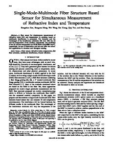
The general block diagram for RNS based FIR filter is shown Fig. 1. Let the moduli set be (m1, m2,…, mr). Then there will be ‘r’ parallel filter channels, which process the signals from the forward converter. The forward converter is shown in dotted lines as it is not used in the proposed design. Finally, the reverse converter combines the signals from all the channels and puts the output signal back in binary form.
r
∏ m . ‘M’ is defined as the dynamic range i
i =1
of the number system. Negative numbers can be represented by partitioning the dynamic range into two sets. A common assignment is that all numbers X, 0 ≤ X ≤ (M/2)-1 are considered positive and the rest are considered as negative. In RNS, arithmetic operations are computed by the formula:
(x1 , x2 ,..., xr ) ⊗ ( y1 , y2 ,..., yr ) = (z1, z2, ..., zr ) where zi = xi ⊗ yi
mi
(1)
Figure 1. RNS based FIR filter
and ⊗ denotes one of the operations of
addition, subtraction or multiplication. Thus arithmetic operations on residues can be performed in parallel without any carry propagation among the residue digits. The process of translating a binary integer X in the range 0 to M-1 to the residue representation (x1, x2,…, xr) with respect to a relatively prime moduli set (m1, m2,…, mr) is called forward conversion. Getting back to the weighted representation of ‘X’ from a given residue representation is referred to as reverse conversion. The reverse conversion can be done using Chinese Remainder Theorem (CRT). CRT computes the binary number directly from its residue and is based on the general formula:
X =
r
∑ a x Mˆ i i
i =1
,
i
ˆ = M and ai = 1 where M i
mi
M
Mˆ i
. The mi
CRT implementation presented in [13] uses ‘r’ ROMs to store
ˆ the precomputed values ai xi M i
M
each indexed by xi. This
reduces CRT implementation to a summation of ‘r’ values, followed by modulo correction with ‘M’ using carry save adder stages and a final carry propagate adder. The overall hardware including the size of ROM stage used in the design is further reduced in [14] by selecting one of the moduli of the form 2n, so that the least significant ‘n’ bits of the binary number are directly available.
1832
III.
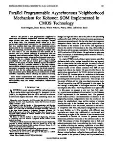
RECEIVER ARCHITECTURE FOR MULTI-STANDARD OPERATION This section deals with direct conversion homodyne receiver architecture as shown in Fig. 2 which is suitable for high integration and multi-standard capability [2]. Homodyne receivers are multi-standard capable because the channel filtering is done at baseband. A wideband high dynamic range sigma-delta (∑∆) modulator is used to digitize both the desired signal and potentially stronger adjacent channel interferers. In this receiver architecture, since the local oscillator (LO) is tuned to the same frequency as the incoming RF frequency to select different standards, it can be programmed to make it suitable for a multi-standard solution. However, the noise and DC offset created at the output of the mixer are to be reduced to achieve adequate dynamic range. SD-ADCs are widely used in wireless systems because of their superior linearity, robustness to circuit imperfections, inherent resolution-bandwidth trade-off and increased programmability in digital domain. A highly linear ∑∆ modulator for multi-standard operation that can achieve high resolution over a wide variety of bandwidth requirements remains challenging. A reconfigurable ADC [16] is a promising solution to keep the power dissipation as low as possible.
Figure 2. Direct conversion homodyne receiver architecture
Single loop and multistage noise shaping (MASH) topologies are two different approaches for implementing ∑∆ modulators. Single loop structures with a higher-order noise transfer function combined with multi-bit feedback can achieve higher dynamic range (DR) with low oversampling ratio (OSR). But the linearity and resolution of the overall ∑∆ modulator are limited by the precision of the multi-bit DAC. MASH topology is preferred over single loop structures since the coefficients are optimized for a specific OSR. It has flexibility to handle different OSRs with little modification. MASH structures can be adopted for multi-mode receivers considering the stability and reconfigurability. The theoretical dynamic range has been used in conjunction with the implementation attributes to choose the optimal topology for different RF standards. The dynamic range DR of a ∑∆ modulator is given by
DR =
3 2 L + 1 2 L +1 B M (2 − 1) 2 2 π 2L
(3)
where L is the order of the modulator, M is the oversampling ratio (OSR), and B is the number of bits of the quantizer. For WCDMA and WiMAX the dynamic range requirements are chosen as 79dB and 69dB respectively. In order to meet the DR requirements demanded by the WCDMA standard, a fourth order cascaded MASH topology is sufficient with a single bit quantizer and an OSR of 16. If WiMAX becomes the target standard, a fifth order topology is a good compromise to achieve the required DR with a 4-bit quantizer and an OSR of 8. The sigma-delta modulator can be made programmable, and all the blocks are switched to operation only in the WiMAX mode. This results in power saving when the receiver is operating in the other mode. Sigma-delta modulator is followed by a programmable decimation filter operating in the digital domain. The proposed work focuses on the design of programmable multistage decimation filter for WCDMA/WiMAX standards, which is highlighted in Fig. 2. PROGRAMMABLE RNS DECIMATION FILTER DESIGN The specifications for WCDMA and WiMAX standards and the corresponding decimation filter design parameters are given in Table I. The oversampling ratio (OSR) for each standard is selected so as to get the required dynamic range for the sigma-delta modulator of a particular order and number of quantizer bits. In order to set the parameters for decimation filter, the receiver specifications and the blocking and interference profiles are defined first. Blockers are large undesired signals within the same cell, while the adjacent channel interferers are large undesired signals from the
neighbouring cells. The interference signals are to be limited within a certain range for each standard for proper reception of the desired signals. The decimation filter is generally designed to minimize undesired signals in the desired band of operation. The output carrier to noise (C/N) ratio is calculated from the bit error rate (BER) of each standard and the modulation scheme used. The passband frequency edge is taken as 80% of the bandwidth. The passband ripples are chosen to minimize signal distortions in the signal band. The stopband attenuations are selected according to the interference profile and C/N ratio for each standard, and are shown in Table I. TABLE I.
STANDARD SPECIFICATIONS AND DECIMATION FILTER DESIGN PARAMETERS
Specification Frequency range(GHz) Channel Spacing Data rate OSR Input sampling frequency, Fs Passband edge Stopband edge Offset frequency (MHz) : Interference magnitude(dBm) C/N ratio Passband ripple Stopband attenuation
WCDMA DL:2.11-2.17 UL:1.92-1.98 5 MHz 3.84 Mchips/s 16 61.44 MHz 2 MHz 2.5 MHz 5 : -63 10 : -56 12.5:-44 7.2 dB 0.5 dB 55 dB
WiMAX 10 - 66 20 MHz 16.704 Msymbols/s 8 133.632 MHz 8 MHz 10 MHz 20 : -68 40 : -49 21 dB 0.5 dB 39 dB
The purpose of a decimation filter is to remove all the outof-band signals and noise, and to reduce the sampling rate from oversampled frequency of the ∑∆ modulator to Nyquist rate of the channel. The decimation filter consists of a lowpass filter and a downsampler. Implementing decimation filter in several stages reduces the total number of filter coefficients. Subsequently, the hardware complexity and computational effort are reduced. This will lead to low power consumption. A multistage sampling rate conversion (SRC) system consists of a cascade of single stage SRC systems as shown in Fig. 3. The ‘ith’ stage performs decimation by a factor of ‘Di’ such that the overall decimation factor ‘D’ is given by D =
P
∏ D , where i
i =1
‘P’ is the total number of stages. The individual filter of each stage is designed within the frequency band of interest in order to prevent aliasing in the overall decimation process.
IV.
1833
Figure 3. Multistage decimation filter
The passband frequency remains the same for all stages. The cut off frequency for the first stage can be less constraining than the overall filter specification. The final-stage filter is responsible for attaining the overall filter requirements, while operating at the lower sampling rate. For stage ‘i’, the passband
The decimation factor is 16 for WCDMA and 8 for WiMAX. Decimation is done in 3 stages with decimation factors of 4, 2 and 2 for WCDMA, and in 2 stages with decimation factors of 4 and 2 for WiMAX. Remez ParksMcClellan optimal equiripple FIR filter is chosen for implementation. The filter orders obtained for WCDMA are 14, 11 and 37 for first, second and third stages respectively. For WiMAX filter orders are 15 and 31 respectively. The block diagram for the programmable decimation filter is shown in Fig. 4, where N1, N2 and N3 denote the filter orders of each stage in each mode. The third filter will be operating only in WCDMA mode and will be bypassed in WiMAX mode using switch S. The switch can be a transmission gate. The first 14 MAC units of first stage filter and first 11 MAC units of the second stage are shared for both modes. The unused hardware in each mode are bypassed to get power saving.
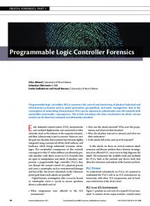
V. SIMULATION RESULTS AND PERFORMANCE ANALYSIS The input sampling frequency is 61.44 MHz for WCDMA and is down-sampled to the data rate of 3.84 Mchips/s in three stages. The cascaded two stage filter structure down-samples the input sampling frequency of 133.632 MHz for WiMAX to the data rate of 16.704 Msymbols/s. The decimation filter responses obtained for WCDMA and WiMAX, satisfying the standard specifications, are shown in Fig. 6 and Fig. 7 respectively. Filter responses of each stage and the cascaded overall responses are shown. Decimation filter response for WCDMA (dB) 0 FIR 1 FIR 2 FIR 3 Overall
-20 Magnitude (dB)
is from 0 ≤ F ≤ Fpc, where Fpc is the passband edge. If Fi -1 and Fi are the input and output sampling frequencies for stage ‘i’, and Fsc is the stopband edge, the transition band for stage ‘i’ is from Fpc ≤ F ≤ Fi –Fsc and the stopband is from (Fi –Fsc) ≤ F ≤ (F i -1 / 2).
-40 -60 -80 -100 -120 0
5
10 15 20 Frequency (MHz)
25
30
Figure 6. Decimation filter responses for WCDMA Decimation filter response for WiMAX (dB)
All the FIR filters are implemented in RNS domain. The moduli set selected for implementation of all the three filters is (25, 29, 31, 37, 43, 47, 59, 64), which provides 43-bit dynamic range. The filter coefficients are taken with 14-bit accuracy. As input to the filter has maximum of 4-bits and the moduli set consists of 5-bit and 6-bit numbers, no forward converter is required in the proposed filter. The reverse converter at the last stage converts filtered outputs from parallel channels to binary form. A filter channel corresponding to modulus ‘mi’ of the first stage is shown in Fig. 5, where ⊗ and ⊕ represent modulo multiplication and addition respectively. Modulo multiplication is implemented with look up table (LUT). The LUT contents can be easily reprogrammed as the mode changes, by implementing the LUTs in FPGA RAM blocks. The modulo adder receives the residue digits and performs usual binary addition, followed by modulo correction if a carry out is produced.
-20
Figure 5. ith filter channel of stage 1
1834
Magnitude (dB)
Figure 4. Dual-mode programmable decimation filter for WCDMA/WiMAX
0 FIR 1 FIR 2 overall
-40
-60
-80
0
10
20
30 40 Frequency (MHz)
50
60
Figure 7. Decimation filter responses for WiMAX
The RNS moduli set (25, 29, 31, 37, 43, 47, 59, 64), consisting of 8 relatively prime integers of 5-bits and 6-bits lengths implements the filters without overflow. It permits filter coefficients of 14-bit accuracy and input word length of 4-bits from ∑∆ modulator. The hardware synthesis is done with Leonardo Spectrum logic synthesis tool from Mentor Graphics. In order to operate first stage filter at 133.632 MHz, pipelining is done after every two modulo adders to meet the critical path delay. Three stage pipelining is done to meet the critical path delay for second filter which operates at maximum frequency of 33.408 MHz. The third stage is used only for WCDMA mode at a frequency of 7.68 MHz and no pipelining is required. The total area requirement and critical path delay of each block of the decimation filter is shown in Table II. The critical path delay and area for each block of the filter is normalized with respect to a full adder critical path delay of 0.45 ns and area of 38µm2. The area requirement of the decimation filter in single
mode WCDMA receiver and the additional area required for making it adaptable for dual-mode operation are given in Table III. It is observed that programmability is achieved at the expense of 24% of additional area compared to single mode WCDMA receiver. TABLE II.
AREA AND CRITICAL PATH DELAY FOR RNS DECIMATION FILTER
Block Filter 1 Filter 2 Filter 3 Multiplexers Reverse converter Total area
Percentage area of each block (%)
Area 2407.29 4925.37 5840.18 29.47 852.82
17.13 35.1 41.6 0.002 6.07
14055.13
100
TABLE III.
Critical path delay 15.39 61.17 244.29 0.69 79.12
REFERENCES [1]
[2]
[3]
AREA REQUIREMENT FOR PROGRAMMABILITY
Type of transceiver
Area
Filter 1 Filter 2 Single Filter 3 mode Reverse WCDMA converter Total Dual-mode Transceiver Additional area for programmability
2220.44 1748.3 5840.18
Percentage area (%)
[4]
75.8
[5]
852.82 10661.74 14055.13
100
3393.39
24.2
[6]
[7]
Table IV reports the characteristics of decimation filter implemented in traditional number system performing signed multiplication and addition. RNS filter implementation offers about 60% saving of area. Pipelining done as in the RNS filter will not meet the critical path delay for traditional case. Here pipelining is to be done in the multipliers as well as in the adder chain. TABLE IV.
hardware in each mode of operation leads to further power saving. As all the filter stages are implemented in RNS and are operating with the same moduli set, a reverse converter is needed only at the last stage output. The performance comparison shows that 60% of area saving is achieved with the proposed RNS implementation compared to a traditional FIR filter implementation. The programmability for dual-mode architecture which could handle both WCDMA and WiMAX, is achieved with an increase in total area only by 24%, compared to that for single mode WCDMA transceiver using RNS implementation.
[8]
[9]
[10]
AREA REQUIREMENT: TRADITIONAL VS RNS Block
Traditional
[11]
Area Filter 1 Filter 2 Filter 3 Total
RNS
VI.
1379.83 12945.88 24536.54 38862.25 14055.13
[12]
[13]
CONCLUSION
[14]
A dual-mode RNS based decimation filter that meets the performance requirements of WCDMA and WiMAX standards, is presented in this paper. The forward converter is eliminated in the proposed filter by suitably selecting the moduli set. Multistage implementation for sampling rate conversion results in reduced hardware complexity and power consumption. Powering down or bypassing of the unused
1835
[15]
[16]
P. Gray and R. Meyer, “Future directions in silicon ICs for RF personal communications,” Proceedings of Custom Integrated Circuits Conference, pp. 83-90, May 1995. C. J. Barrett, “Low-power decimation filter design for multi-standard transceiver applications”, Master of Science in Electrical Engineering, University of California, Berkeley. S. R. Norsworthy, R. Schreier and G. C. Temes, Delta-Sigma Data Converters, Theory, Design, and Simulation, Piscataway, NJ: IEEE Press, 1997. Y. Gao, L. Jia and H. Tenhunen, “A fifth-order comb decimation filter for multi-standard transceiver applications”, IEEE Int. Symp. on Circuits and Systems, Switzerland, May 28-31, 2000. A. Ghazel, L. Naviner and K. Grati. “Design of down-sampling processors for radio communications”, Analog Integrated Circuits and Signal Processing, 36, Kluwer academic publishers, pp. 31-38, 2003. J. L. Tecpanecatl-Xihuitl, A. Kumar and M. A. Bayoumi, “Low complexity decimation filter for multistandard digital receivers”, IEEE Int. Symp. on Circuits and Systems, Vol. 1, pp. 552- 555, May 2005. S. D’ Amico, M. De Matteis and A. Baschirotto, “A 6.4mW, 4.9nV/√Hz, 24dBm IIP3 VGA for a multi-standard (WLAN, UMTS, GSM and Bluetooth) receiver”, 32nd European Solid-State Circuits Conference, pp. 82-85, September 2006. Ze Tao and S. Signell, “Multi-standard delta-sigma decimation filter design”, IEEE Asia Pacific Conference on Circuits and Systems (APCCAS 2006), Singapore, pp. 1212-1215, Dec. 2006. F. Sheikh and S. Masud, “Efficient sample rate conversion for multistandard software defined radios”, IEEE Int. Conf. on Acoustics, Speech and Signal Processing, HI, pp. II-329 – II-332, Apr. 2007. W. Li, J. Liu, J. Wang, C. Zhang and W. Guo, “An efficient digital IF down-converter for dual-mode WCDMA/EDGE receiver based on software radio”, IEEE 6th CAS Symp. on Emerging Technologies: Mobile and Wireless Comm., China, pp. 713-716, May 31-June2, 2004. M. Kim and S. Lee, “Design of dual-mode digital down converter for WCDMA and cdma2000”, ETRI Journal, Vol.26, No.6, Dec. 2004, pp.555-559. J. Ramírez, A. García, U. M-Baese and A. Lloris, “Fast RNS FPL-based communications receiver design and implementation”, FPL 2002, LNCS 2438, pp. 472-481, Sept. 2002. B. Parhami and C.Y. Huang, “Optimal look up schemes for VLSI implementation of input/output conversions and other residue number operations,” in VLSI Signal Processing VII, J. Rabaey, P. M. Chau and Eldon, eds., IEEE Press, New York, 1994. D. Radhakrishnan, T. Srikanthan and J. Mathew, “Using the 2n Property to Implement an Efficient General Purpose Residue-to-Binary Converter”, proceedings SCS '99, Iasi, Romania, July 1999, pp. 183-186. G. L. Bernocchi, G.C. Cardarilli, A. D. Re, A. Nannarelli and M. Re, “Low-power adaptive filter based on RNS components”, IEEE Int. Symp. on Circuits and Systems, pp. 3211-3214, May 2007 Andrea Xotta, Andrea Gerosa and Andrea Neviani, “A multi-mode ∑∆ analog-to-digital converter for GSM, UMTS and WLAN,” IEEE Int. Symp. on Circuits and Systems, vol.3, pp. 2551-2554, May 2005.