offshore environments such as ocean-floor exploration is presented. ..... The authors would like to thank Research & Development. Corporation of Newfoundland and Labrador for sponsoring .... http://robot.kaist.ac.kr/paper/article.php?n=53.
Robot Arm Manipulation Using Depth-Sensing Cameras and Inverse Kinematics Akhilesh Kumar Mishra
Oscar Meruvia-Pastor
Department of Computer Science
Department of Computer Science
Memorial University of Newfoundland
Memorial University of Newfoundland
Akm565-at-mun-dot-ca
Oscar-at-mun-dot-ca
ABSTRACT: In this work we propose a new technique to manipulate a robotic arm which uses a depth camera to capture the user input and inverse kinematics to define the motion of the robotic arm. The presented technique is inexpensive to implement and easier to learn as compared to the current methods. Along with the easier manipulation of the robotic arm, the presented approach also adds some simple speech and gesture commands to control the end-effector which makes the interaction more intuitive.
pick, drop and rotate the objects more intuitively and easily. The presented approach requires less training and hence is less expensive as compared to the conventional manipulation and training techniques.
KEYWORDS: inverse kinematics, gesture control, speech recognition, robot control, manipulation, interaction. I.
INTRODUCTION
A technique for remotely operating a robotic arm in offshore environments such as ocean-floor exploration is presented. With this approach the user can remotely manipulate the arm which is placed at the seabed either from an offshore platform or from the ship. Existing manipulators for robotic arms such as Titan IV are operated via cabled controllers. Operators of these controllers require a lot of training and experience before they apply their skills in the field. As the operated arm is deployed under the ocean training a user to control the arm is expensive and risky. There are, however, computer simulators which are used to train users on particular manipulator arms. For example, GRI Simulations Inc.’s Manipulator trainer (see Figure 1) [4] does this job for a variety of manipulators for underwater devices and vehicles. Figure 1 shows the simulation of a robotic arm placed under water, the user can use the commercial controller for training and controlling the arm. Existing manipulators for robotic arms such as Titan IV work on forward kinematics where the user needs to control each joint of the robotic arm manually. Also, commercial simulators work using forward kinematics and require a high degree of skill from the operator and thus extensive training. This paper presents an approach in which the user just needs to point to the target and the robotic arm reaches the target on its own using Inverse Kinematics (IK). The user input is captured using a depth camera and passed to the controller module which calculates the joint angles or controls the end-effector. Speech and gestures commands were added so that the user can control the end-effector to
978-1-4799-4918-2/14/$31.00 ©2014 IEEE
Figure 1: The robotic arm in a simulated underwater operation. Image courtesy GRI Simulations Inc. II.
RELATED WORK
Currently there are many techniques for manipulating a robot arm, involving position-controlled manipulators [4, 25], joystick based controllers [21, 22], speech and gesture based controller [24, 7, 9], and sensor based interfaces [6]. Position-controlled manipulators such as Titan IV master controller, Figure 2, are used for training of remotely operated underwater vehicles (ROUVs) and are quite expensive [4, 25]. Also, for people who lack muscle control or who has partial paralysis joystick or position based controller is not a good method. Another method in which the users interact with the robotic arm using speech, helps people with motor impairment, however it cannot be used for complex manipulation tasks where the robot is deployed in adverse conditions such as at the ocean’s floor, and some industrial or medical applications. In another approach, called perception by proxy [7], the interface uses stereo cameras to obtain the information about the surroundings, which allows the operators of the robots to perform their tasks faster. It uses stereo cameras instead of depth cameras to obtain the accurate depth information about the obstacles in the environment. There are existing methods which use stereo cameras [9,18, 7] or depth cameras like Microsoft Kinect to control a robot, for example H.B Suay’s approach to control a humanoid using depth cameras [9]. This method
uses depth images and skeletal tracking software to control the humanoid robot. This method is mostly suited for humanoids where the hand and leg gestures are mapped to the appropriate part of the humanoid; however for a robotic arm we need a different type of controller and intuitive interface. The work proposed here provides a more intuitive and easy interface to manipulate a robotic arm using an Intel’s depth sensing camera.
Figure 4: Target ball positions w.r.t user’s hand position
Figure 2: Position-controlled manipulator for Titan IV [23], image courtesy GRI Simulations Inc.
The 3D coordinates of the ball are passed as input to the IK module. Figure 5 shows the simulator and the depth camera interface.The camera field of view is mapped to the users hand as shown in Figure 6.
III SYSTEM OVERVIEW The block diagram of the overall system is shown in Figure 3. The user specifies the target position by moving his/her hands in front of a depth sensing camera. The depth camera returns the coordinates of the users’ hand and the coordinates are passed as target position to the inverse
Figure 5: User interacting with the simulator using depth camera
Figure 3: System Overview
kinematics module, where the joint angles for the arm simulator are calculated.After the joint angles have been calculated the robot arm simulator module applies the rotations calculated and the end-effector reaches the target. Once the target position has been reached the user can issue a voice or a gesture command to interact with the endeffector control module to pick and drop the objects. IV
HAND-DRIVEN
COMMANDS
USING
DEPTH
CAMERAS
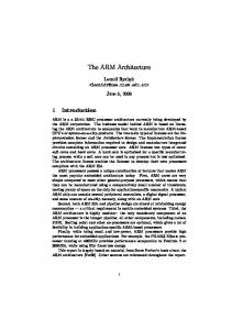
Intel’s Creative depth camera was used to get the data about the user‘s hand position. The camera SDK [5] provides the hand position and its distance from the camera. This is used to control a target ball which can move in 3D input space. Figure 4 shows how the ball moves into the scene with respect to the user’s hand.
Figure 6: The 3D input space As shown in Figure 6, the user controls the ball in 3 dimensions using his/ her hand. Placing the hand on the center of the grid stops the motion of the target ball. The grid cells Up, Down, Left, Right, Near and Far show the direction of motion. For example, if the hand is in the Up grid then the ball’s Y coordinate will be incremented by 1 as long as the hand is in Up grid. Similarly, if the hand is in Down grid then the ball’s Y coordinate will be decremented by 1 for as long as the hand is in Down grid. Likewise, the user interacts with X and Z coordinates as well.
V INVERSE KINEMATICS MODULE Inverse Kinematics is a technique in which the user specifies a target position or pose for an articulated object, and an algorithm or system computes a solution to move the articulated object from the existing position to the target position. In our case, we deal with an articulated arm that corresponds to the joints of a robotic arm such as Titan IV [23]. As shown in Figure 7A the user specifies the target position (x, y) and the joint angles θ1 θ2 and θ3 calculated using the algorithm. There are several algorithms for solving IK, coming originally from robotics applications. The most popular ones include Cyclic Coordinate Descent methods
as close to the target as possible [1] [2]. The algorithm starts by measuring the difference between the two vectors formed between the effector position Pe to Pc and from Pc to target position Pt. It then calculates the rotation and direction to reduce this difference to zero (see Figure 8). It does this for each joint, iterating from the endeffector to the root joint of the kinematic chain. The rotation is calculated by the dot product of two vectors and the direction is calculated by the cross product of two vectors defined in pseudo-code for the CCD algorithm below [1]. (1)
(2) To reach the target the equations (1) and (2) shown below are solved for each joint until the difference between the end-effector and target is zero or the number of iterations has reached its limit. Figure 7: (A) 3 Link Manipulator (B): Robot arm simulator developed in OpenGL.
The basic pseudocode of the 2D CCD algorithm is shown below:
[1, 2], Pseudoinverse methods [3] Jacobian transpose [10], [11] and Triangulation method. [12]. One of the recently introduced inverse kinematics algorithms like quadratic minimization [13] and [17] delivers robust and efficient inverse kinematics solutions .Masayuki Shimizu proposed an analytical methodology of inverse kinematic solution for 7 DOF manipulators with joint limits. This method focuses on finding the inverse kinematics solutions where the joint movements are constrained [16]. For this research Cyclic Coordinate Descent algorithm was used to solve the IK problem, because of its simplicity and computational efficiency [1] Figure 7B shows the robotic arm simulator used for this research, developed in OpenGL. The yellow ball is the target ball which the user controls by using one of the interface options: keyboard, joystick or depth camera manipulation. This simulator has 4 joints, joint 0 is the base, which can be rotated around the Y axis and joints 1, 2 and 3 rotate around the Z axis.
Pseudo-code 1: CCD algorithm (Tx ,Ty) : Target coordinates (Ex, Ey) : End Effector coordinates Xi, Yi) :Position of i-th link Ti: Target vector for i-th link = (TxXi, Ty-Yi) Vi : End Effector vector for i-th link = (Ex-Xi, Ey-Yi) Ai : Angle between Ti and Vi FOR i = n to 1 // Where n is the number of joints. Ti = (Tx-Xi, Ty-Yi) Vi = (Ex-Xi,Ey-Yi) Ai = Ti.Vi/(|Ti|*|Vi|) Rotate ith link by Ai such that Vi aligns with Ti END FOR
Cyclic Coordinate Descent: CCD solves the IK problem through optimization. Looping through the joints from end to root, each joint gets adjusted so as to get the end effector
Figure 9: 2D inverse kinematics is obtained on the X’Y plane.
Figure 8: CCD algorithm, the end-effector rotates to make θ zero.
The previous algorithm is used to get the inverse kinematics solution in 3D as well by applying a simple rotation across Y axis as shown in Figure 9. In Figure 9 “T” shows the target point on the rotated X’Y plane.
Pseudo-code 2: Rotation of the joint 0 at the base:
moving the arm’s end effector towards the target ball.
STEP 1: Get the 3D target coordinates of the target ball STEP 2: Calculate the baseAngle using arc tangent and apply the rotation to target point on X’Y plane. STEP 3: Find the solution using 2D inverse Kinematics algorithm on X’Y plane. STEP: Applying the rotation to all joints. VI
END-EFFECTOR CONTROL MODULE
The task that we are implementing with this IK system is a picking and dropping task, where objects are picked from the vicinity of the robot arm, and the user can drop them at different locations. This module uses the Intel SDK’s[5] speech processing and image processing APIs to let the user interact with the end-effector using speech commands like “Pick”, “Drop” for picking and dropping the objects from end-effector. The user can also use the “Thumbs up” or “Thumbs down” gestures for pick and drop commands. Once the joint angles have been calculated the user can interact with the End-effector and grab/ release the objects by speech, hand gesture, keyboard input or joystick command. This module also checks for any possible collisions of end-effector and obstacles. Following is a basic outline of the collision detection algorithm. Algorithm for collision detection: (Ex, Ey): Position of End-effector (Ox,Oy) : Position of Obstacle Re: Radius of Sphere surrounding Endeffector Ro: Radius of sphere surrounding obstacle d: Distance between obstacle and endeffector Calculate d; d = sqrt( (Ex-Ox)2+(Ey-Oy)2 ) IF d