will certainly encounter unknown objects, or due to sensor uncertainty, it might .... steepness of the grasp, β influences the direction of the grasp, δ defines the final distance between ... collisions by maximizing the distance of the object to the.
Robotic grasping of unmodeled objects using time-of-flight range data and finger torque information Alexis Maldonado, Ulrich Klank and Michael Beetz Intelligent Autonomous Systems, Technische Universit¨at M¨unchen, Germany {maldonad, klank, beetz}@in.tum.de
Abstract— Robotic grasping in an open environment requires both object-specific as well as general grasping skills. When the objects are previously known it is possible to employ techniques that exploit object models, like geometrical grasping simulators. On the other hand, a competent system will also be able to deal with unmodeled objects using general solutions. In this paper we present an integrated system for autonomous rigid-object pick-up tasks in domestic environments, focusing on the gripping of unmodeled objects and exploiting sensor feedback from the robot hand to monitor the grasp. We describe the perception system based on time-of-flight range data, the grasp pose optimization algorithm and the grasp execution. The performance and robustness of the system is validated by experiments including pick-up tasks on many different common kitchen items.
I. INTRODUCTION Our goal is to build a general and competent control system for mobile manipulation robots performing pickand-place tasks in human environments. We can expect to have information and detailed models of many of the objects present, and this should be employed to the greatest possible advantage; but in any open environment the robot will certainly encounter unknown objects, or due to sensor uncertainty, it might fail to recognize known ones. To deal with these issues we are developing a pick-andplace control system that employs two general classes of grasping strategies: (1) informed grasping strategies that use models of the objects to plan or infer adequate grasping actions using the model as an information resource and (2) general methods that can grasp objects successfully without having model information and just relying on single view sensor data. In this paper we investigate the second class of grasping strategies, the ones applicable without having prior models. An overview of this grasping strategy is shown in Figure 1: The robot, which is depicted in Figure 2, is ordered to grasp an object on a table, so it moves its time-of-flight camera and obtains a point-cloud of the table and the object. The object of interest is segmented from the point cloud, and a Gaussian point distribution representation is calculated (Sec. IV). This is the simplest model that can represent the position, size and orientation of the object including the perceptual uncertainty. We then use a simplified model (Fig. 7) of our robotic hand to find a good hand orientation and approach vector considering obstacles. The main contributions of this paper are: (1) A perception system based on time-of-flight range data that represents objects as Gaussian point distributions. (2) A grasp pose
Fig. 1.
Overview of the proposed system.
optimization algorithm. (3) A method to incorporate torque sensors in the fingers to detect collisions and improve grasping. Briefly said, we present a working system that uses 3D perception with a time of flight (ToF) camera and torque sensors in the fingers to reliably manipulate a large set of unmodeled objects. For a video demonstration, see [1]. II. RELATED WORK Natale et al [2] present a system that deals with great uncertainty in the position of the manipulator by using tactile feedback to explore the objects. This is inspiring work for incorporating sensors in the robot’s hand. We calibrate our robot to be able to act quickly and accurately when the sensors allow it, and follow the same idea of exploration when the estimates of position and/or size were not precise. Another very interesting work shows manipulation of textured objects based on a single view [3]. A very advanced system was presented on a HRP-2 in [4]: it additionally includes the verification of a manipulation task by vision in daily life environments, this system also uses previously known objects and visual modalities and a simple hand, while it uses the full body for manipulation. Saxena et al describe an advanced system to grasp novel objects using visual [5] and ToF [6] information. One important difference is that our system does not need training data and that it uses the torque sensors from the hand to monitor and improve the grasp. A simple grasp planning was shown by Vahedi and Stappen presented in [7] for a three fingered hand could encage a polygonal region, and could approximate a grasp in a computationally complexity in O(n3 ) (n = length of Polygon). In contrast we present here a fast probabilistic encaging of an unmodeled object including a set of unmodeled obstacles.
The work of Geidenstam et al. [8] has shown grasp planning of previously unmodeled objects, which unfortunately requires on the one hand high quality input measurements and on the other hand relatively high computation time. Geometrical-simulation grasp planners like GraspIt [9] require object meshes or CAD models to work, or at least point clouds with approximated faces and normals. Both are not necessary for our approach. III. ROBOT PLATFORM Our mobile manipulation robot ’TUM-ROSIE’ is depicted in Fig. 2. The components used for the system described in this paper are: a KUKA omnidirectional platform, two KUKA LWR-4 7-DOF lightweight arms, two DLR-HIT hands acting as end-effectors, an Amtec-Robotics PW-070 pan-tilt unit, and a SR4000 time-of-flight camera from MESA Imaging. There are two on-board computers running Debian GNU/Linux, and we use extensively the YARP[10] and ROS[11] middlewares, which also allows us to run parts of the system on additional computers. The arms are controlled over an independent Ethernet connection using KUKA’s Fast Research Interface (FRI) to send joint-velocity commands at 500Hz.
Fig. 2.
Our mobile manipulation robot grasping an unmodeled object.
Fig. 3. Robot’s camera view while grasping a cup. Objects are often partially occluded during grasping.
IV. PERCEPTION: P OINT- CLOUD SEGMENTATION AND OBTAINING THE G AUSSIAN POINT DISTRIBUTION We work towards robotic agents that excel at manipulating everyday household objects. The methods we use are detailed
Fig. 4. The robot observes a cup. On the left, an RGB camera image, and on the right, two different views from the point cloud data.
Fig. 5. On the left, a Gaussian point distribution correctly represents the cup. Middle and right: One chosen grasp pose from different perspectives.
in [12], [13], [14]. Our system has a wide spectrum of algorithms going from general obstacle detection to specific object recognition and localization, but here we will concentrate on the detection of unmodeled objects. The perception system uses data from a time-of-flight range camera mounted on the Pan-Tilt unit. Fig. 4 shows ToF data from a cup. The 3D data is very noisy and incomplete (mostly only the front face of the object can be seen). Both facts are clearly noticeable by looking at the point cloud from a different perspective as the sensor. Our robot operates in a kitchen environment, so we use the assumption that the objects we would like to manipulate will be placed on a plane, usually the table top or the counter top. The system will identify a supporting plane on the point cloud, and the unknown objects can be easily found by separating the points that protrude from that plane. Then the points are clustered based on the euclidean distance and for each cluster, the system returns one Gaussian point distribution. The mean and covariance matrix of the point distribution represent an approximated hull of the object. This representation of the cluster is very compact: 3 numbers representing the position of the center, and a 3x3 matrix that represents the shape. All the detected objects are used by the manipulation system. One of them is chosen as the object to grasp, and the rest are considered as obstacles for that grasp-action. This algorithm works reliably, even considering that the ToF camera can be very noisy in some situations. An example of the point cloud data can be seen in Fig. 5, including small colored group of axes that represent the covariance in 3D. It can be seen that the point distribution represents the original object closely. Some objects, like the Ice Tea box seen in Fig. 8 are only partially perceived by the ToF camera, so the point distribution will be smaller than the real object. In Section VI we explain how we deal with this issue.
All the kinematic chains that are involved are precisely calibrated (e.g. the mounting position of the ToF camera, or the pose of the Pan-Tilt unit). A small error of one or two degrees in the pose of the camera will translate to several centimeters of error in the estimated position of the objects. Our current calibration assures a residual spatial error under a centimeter, which is substantially lower than the expected noise of our ToF camera. V. GRASP POSE OPTIMIZATION BASED ON GAUSSIAN POINT DISTRIBUTIONS Given our simple representation of the position and shape of the object, our grasp planner has to find an appropriate pose where the robot can execute a general force-closure grasp, like a 3-finger-pinch.
(hand rotation) we get the following function for calculating T a Point Pδi = [xi , yi , z i ] on the approaching phase toward Q at distance δ : (δ − z)cαsβ + cβ xi − sαsβ yi Pδi (α, β , Q) = Q + (δ − z)cαcβ + sβ xi + sαcβ yi , (3) (δ − z)sα + cαyi where cα denotes cos(α) and sα denotes sin(α). If we introduce now a special distribution case of objects, that have a clean major axis along the robot’s Z axis (equal to the table’s normal), we get this special case for the covariance: sx c 0 (4) Σz = c sy 0 0 0 sz
This special Σ allows a general minimization for an optimal α. Which can be expressed by arg min f (Pδ (α, β ), Q, Σ)
(5)
α
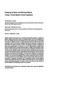
Fig. 6. We parametrize the grasp with three values: α influences the steepness of the grasp, β influences the direction of the grasp, δ defines the final distance between hand center and the object center.
Our strategy is to find a hand pose that brings the center of the palm as close as possible to the object, while avoiding collisions by maximizing the distance of the object to the points representing the fingers. These contradicting goals can be jointly solved using our representation of measurements of unknown objects as a point distribution: We model all objects as a Gaussian distribution of material around the estimated object center µ with a covariance Σ, see section IV. We can approximate the probability of a collision of a finger tip position P = [x, y, z]T with the object at Q = [µx , µy , µz ]T by (1) d(P, Q) = [x − µx , y − µy , z − µz ]T � � 1 1 exp − d(P, Q)Σ−1 d(P, Q)T f (P, Q, Σ) = p (2) 2 c det(Σ)
based on the standard Gaussian probability density function for joint random variables with c = (2π)3/2 . The random variables are here the three components of Q. Those components are not independent since we measure the end effector position in terms of the arm, while measuring the objects in terms of the camera. Given this function f we can now evaluate a certain grasp and we can calculate an optimal grasp regarding this criteria. Figure 6 shows how we parameterize the position of the hand with the angle out of the x-y plane α (approaching angle, defined positive) and one angle around the z-axis β
This minimum can be estimated by set the derivative of f equal to zero, while setting Q = [0, 0, 0]T without loss of generality: ∆ f (Pδ (α), [0, 0, 0]T , Σz ) = 0, (6) ∆α which results in two solutions solving for α independent from all other parameters: α1 = 0, α2 = π2 . The result is intuitive: if an object is placed upright on a table, we only have to evaluate if we better grasp from the top or from the side. This does not hold for any inclined objects or any objects placed on a ramp, but it is valid for most household items and all our test objects.
Fig. 7. Simplified hand model. Red circles indicate the points used in the kinematic model. The yellow circle shows the origin of the hand reference frame. The left hand is shown.
In order to characterize the hand properties we define a set of points Pδ0..9 . They are shown in Fig. 7. Pδ0 and Pδ1 describe the connection between thumb and the other fingers, which is a critical collision point. Pδ1..9 are the positions of the other fingers. All Pδi are just defined like Pδ with a constant offset in hand coordinates, which can be easily derived from Q, α and β . We defined the z-axis of the hand so that it starts at Pδ0 , and it points towards the object at Q. This axis is controlled by the two parameters α and β while the palm is along the y-axis, which is normal to the plane described by the z-axis of the object and the hand. Basically, the hand-model is a kinematic tree representing the fingertips and internal points of the palm. The simplified error function for a point under the given assumptions is then: π fs = min( f (Pδi (0, β , Q), Q, Σ), f (Pδi ( , β , Q), Q, Σ)) (7) 2
Which leads to the best configuration for an object floating in free space: 9
[β , α] = arg min ∑ fs (i, δ , β , Q, Σ) β ,α
(8)
i=0
where β is, due to the symmetry of our point distribution, a value between − π2 and π2 and α = 0 or π2 . The choice of δ which is a value between min(sx , sy , sz ) and (max(sx , sy , sz ) + f ingerlength) not only depends on this collision probability, but also on the enclosure probability, which is inversely correlated with δ . Then it requires an additional optimization for this parameter. Incorporating the table leads to further reduction of the parameter space in α and δ for small objects: µz − ztable
ztable + f ingerlength
(9)
Further objects on the table at position Q j = [µxj , µyj , µzj ] must be considered if they conflict with the arm trajectory. This only is the case, if the two following conditions hold: µz − µzj < szj r�
�2 � �2 µx − µxj + µy − µyj
Fig. 8.
Visualization of selected grasps in a scene.
VI. GRASP EXECUTION AND SUPERVISION > f ingerlength
π fsj = min( f (Pδi (0, Q), Q j Σ j ), f (Pδi ( , Q), Q j , Σ j )) 2
(11)
(12)
This adaption can be incorporated into Eq. 8, which now can calculate the desired grasp configuration in our setup in a few iterations over δ and β . The optimization process should best start at a β corresponding to the smallest extension of the object and at the smallest possible distance δ , searching for the first local minimum. This adaption of Eq. 8 follows: 9
[β , α] = arg min ∑ ∑ fsj (i, δ , β , Q, Q j , Σ j ) − aδ β ,α
(c) Resulting grasp position on the (d) Resulting grasp position on the ice tea box(top view). ice tea box (side view).
(10)
All relevant obstacles are collected in O = [Q, Q1 , Q2 ..QN ] and S = [Σ, Σ1 , Σ2 ..ΣN ]. Both variables contain as a first element the object to grasp, and subsequently all detected obstacles. Eq. 7 can be generalized for an obstacle:
N
(a) A scene seen by the robot’s RGB (b) Scene data from the ToF camera. camera. Calculated grasp poses are shown.
(13)
j=0 i=0
where N denotes the number of obstacles which can be adapted during the grasp in case of unexpected collisions of the hand with the target object. aδ is a factor charging for a further delta depending on the number of finger points and δ . The added Q j would be the finger position at the time of collision and Σ j will be the uncertainty of the hand obstacle relation at this time, which we assumed constant. If a collision is detected during the execution of the approach and grasp movement, the hand is moved back and a new calculation of the optimal grasping pose is done. To conclude this section, we have shown a simple error measurement that allows searching on only three variables for a good grasping pose taking into account possible obstacles during the approach to the grasp position.
A. Detection of collisions in the fingers As was seen at the end of Section IV, it is possible that the perception system underestimates the size of the object of interest due to occlusion, or measures the object’s position inaccurately due to sensor uncertainty. Executing a ’blind’ or sensor-less grasp procedure will not be reliable due to the important effect caused by small errors in the pose estimation or calibration. The best place to get information about the object being manipulated are the fingers themselves since they are the closest and most reliable source of contact information. The DLR-HIT hand is equipped with three torque sensors on each finger, placed near each joint. Our hand controller reads torque data constantly from the fingers, and uses it to detect collisions with the object during the approach phase. A collision can simply be detected by applying a threshold on the filtered torque streams, as can be seen in Fig. 9(b). Sensing and positioning of the arm will always have uncertainties, so we employ a haptic approach to make the grasping more robust: A detected collision event on any finger indicates that our estimation of the object’s shape and/or position was wrong, but we can use the position of the collision to improve the estimation, so the system can locally correct the grasp. See Eq. 13 where the results are taken into account. Basically, the hand is moved back, the position where the crash was detected is put back into the grasp planner as a possible obstacle, and a new grasp pose can be calculated. The system also checks if the new desired position is reachable by the hand using a position-inversekinematics algorithm, and can look for other grasp positions until it finds an appropriate one. Since this algorithm is designed to put the fingers around
Object Tape roll White Porceilain cup Blue Porcelain cup Melitta Coffee Filters Small Paper Towel Melitta Coffee Filters Big Assam-Blend Tea box
(a) Approach, collision, pull-back, grasping using the corrected pose.
Can of Peas Soup Box (Heisse Tasse) Green Teapot Peppermint Tea box Nivea Shower gel Iced Tea Leibniz cookies Paper cup
Size(WxHxD in cm)
5x5x4 6x6x4 6x6x4 2x5x7 28x7x7 4x8x20 7x10x17 11x7x7 11x7x7 22x17x12 16x7x6 17x8x3 27x10x10 22x7x4 6x6x4
Total
Success/Trials
2 4 3 2 4 4 4 4 4 1 4 1 4 4 3 48
/ / / / / / / / / / / / / / / /
4 4 4 2 4 4 4 4 4 1 4 8 4 4 4 59
TABLE I R ESULTS OF THE GRASPING EXPERIMENTS ON HOUSEHOLD ITEMS .
(b) Base torque data for the middle finger. Fig. 9. The collision with the object can clearly be detected based on the torque data. The finger was in contact with the object for 0.3 seconds.
the object as closely as possible, all that is needed is a simple enveloping grasp. We chose a 3-finger pinch on our DLR-HIT hands, but the same algorithm would work with a parallel-finger manipulator (with torque sensors installed to detect crashes on the fingers).
of objects and obstacles. (3) calculates approach and grasp poses using the grasp pose optimizer. (4) configures the vector field accordingly, moves the arm, deals with collisions. (5) executes a 3-finger pinch on the hand. (6) lifts the object, and evaluates the grasp. (7) drops the object at a pre-defined location. Errors can be detected during each step of the procedure, and the controller takes corrective action, e.g. moving the hand out of the way, and detecting objects again if the grasp was not successful.
B. Motion control In order to guide the motion of the arm and the hand for manipulation, we employ a system based on vector fields [12], where it is possible to create point attractors, as well as planar and spherical repellers. We can easily encode the available information from the environment: the desired pose of the end effector, and all the detected obstacles. The KUKA LWR-4 arms are being operated in JointImpedance mode, with a low stiffness set for each joint for safety. The arm could be pushed by a person or have a collision at any time, and the motion controller should deal with this gracefully and continue towards the desired pose while avoiding obstacles. For this reason, we do not pre-calculate any trajectories. Our current implementation has an on-the-fly reconfigurable vector field that decides the direction in which the end effector of the arm should move, and it feeds this to a damped least squares inverse kinematics algorithm for finding the joint velocities. This loop runs in real time (currently 240Hz). The vector field also observes additional constraints, like the distance of each joint to its limits, or the distance of the whole arm posture to a preferred one, and influences the inverse kinematics algorithm by changing constantly the joint-weights (affect the relative movement of the joints), or task-weights (affects how much importance is given to position or orientation in Cartesian space). For the experiments described in this paper, we used a relatively simple high-level controller that: (1) moves the hand and the arm out of the view of the sensors in the head. (2) asks the visual perception system for positions
VII. EXPERIMENTAL RESULTS The following experiments show the robustness of the proposed grasping system for unmodeled objects, as well as the entire system accuracy. A. Handling Different Objects
Fig. 10.
The household items used for testing. Results in Table I.
The test set contains 15 objects which can be seen in Figure 10. We consider a grasp attempt successful if the object was lifted from the table, and held in the hand for at least 10 seconds. The statistics about successful grasps can be found in Table I. The robot grasped correctly the majority of the random kitchen objects. The overall success was approx. 80 percent, decreasing mostly due to one object (“Nivea shower gel”), that was difficult to grasp. Since the system can recognize failed grasp attempts, it can repeat the action (including perception), and this would improve the reliability.
reach the desired position perfectly because of low stiffness and external interference. IX. FUTURE WORK
(a) Grasping
(b) Lifting
(c) Avoiding an obstacle
(d) Dropping
Fig. 12. This sequence illustrates a transport task using collision avoidance.
B. Cleaning up a cluttered scene Another experimental setup can be seen in Fig. 11, where the task is to clear the table by picking up the objects on it. The robot successfully picked up all objects one after the other.
Fig. 11.
Grasping all the objects from a cluttered scene
C. Handling Obstacles After choosing an object to grasp, the remaining clusters are configured as obstacles for the vector field. The obstacle avoidance was tested by grasping an object and ordering the robot to drop it in a position where it would likely collide with obstacles on the way. Figure 12 shows different stages of this task. VIII. CONCLUSIONS The presented system is able to reliably grasp unmodeled objects by extracting a minimal representation from the point cloud data, which can also be easily communicated to our vector field controller for the robot arm, allowing the robot to retrieve objects in cluttered situations, and move them avoiding collisions under non-excessive clutter. By using torque information from the fingers, it is possible to detect collisions with the objects during grasping, and improve the object estimate to appropriately grasp, even if the estimated position was inaccurate or the arm did not
We are currently integrating a grasp planner that uses meshes of the hands/objects to evaluate possible grasps. The idea is to use it for known objects, and fall back to the system described here when no model can be found. We also plan to extend the sensing capabilities of the hand to have more accurate information about the objects in it, as well as detect slippage very early in the grasp. With this additional information, it would be possible to correct a failing grasp attempt. We will release the code used for these experiments under a free software license, as a part of the official TUM ROS repository at http://tum-ros-pkg.svn.sourceforge.net/viewvc/tumros-pkg/stacks/grasping/ . ACKNOWLEDGMENTS This work was supported by the CoTeSys (Cognition for Technical Systems) cluster of excellence and MVTec GmbH.
R EFERENCES [1] A. Maldonado, “Youtube - robot grasping unmodeled objects using time-of-flight and torque data,” Video posted to: http://www.youtube.com/watch?v=IhnyqMoRbfw, March 2010. [2] L. Natale and E. Torres-Jara, “A sensitive approach to grasping,” 2008. [3] A. C. Romea, D. Berenson, S. Srinivasa, , and D. Ferguson, “Object recognition and full pose registration from a single image for robotic manipulation,” in IEEE International Conference on Robotics and Automation (ICRA ’09), May 2009. [4] K. Okada, M. Kojima, Y. Sagawa, T. Ichino, K. Sato, and M. Inaba, “Vision based behavior verification system of humanoid robot for daily environment tasks,” in Proceedings of the 6th IEEE-RAS International Conference on Humanoid Robots (Humanoids), 2006, pp. 7–12. [5] A. Saxena, L. L. S. Wong, and A. Y. Ng, “Learning grasp strategies with partial shape information,” in AAAI, 2008, pp. 1491–1494. [6] A. Saxena, J. Driemeyer, and A. Ng, “Robotic grasping of novel objects using vision,” The International Journal of Robotics Research, vol. 27, no. 2, p. 157, 2008. [7] M. Vahedi and A. F. van der Stappen, “On the complexity of the set of three-finger caging grasps of convex polygons,” in Proceedings of Robotics: Science and Systems, Seattle, USA, June 2009. [8] S. Geidenstam, K. Huebner, D. Banksell, and D. Kragic, “Learning of 2D grasping strategies from box-based 3D object approximations,” in Proceedings of Robotics: Science and Systems, Seattle, USA, June 2009. [9] C. Goldfeder, M. Ciocarlie, H. Dang, and P. Allen, “The Columbia Grasp Database,” in International Conference on Robotics and Automation (ICRA), 2009. [10] G. Metta, P. Fitzpatrick, and L. Natale, “YARP: Yet Another Robot Platform,” International Journal of Advanced Robotics Systems, special issue on Software Development and Integration in Robotics, vol. 3, no. 1, 2006. [11] M. Quigley, K. Conley, B. Gerkey, J. Faust, T. Foote, J. Leibs, R. Wheeler, and A. Ng, “Ros: an open-source robot operating system,” in In IEEE International Conference on Robotics and Automation (ICRA 2009), 2009. [12] M. Beetz, F. Stulp, P. Esden-Tempski, A. Fedrizzi, U. Klank, I. Kresse, A. Maldonado, and F. Ruiz, “Generality and legibility in mobile manipulation,” Autonomous Robots Journal (Special Issue on Mobile Manipulation), vol. 28, no. 1, pp. 21–44, 2010. [13] U. Klank, D. Pangercic, R. B. Rusu, and M. Beetz, “Real-time cad model matching for mobile manipulation and grasping,” in 9th IEEERAS International Conference on Humanoid Robots, Paris, France, December 7-10 2009. [14] U. Klank, M. Z. Zia, and M. Beetz, “3D Model Selection from an Internet Database for Robotic Vision,” in International Conference on Robotics and Automation (ICRA), 2009.