Robotics 2015, 4, 103-119; doi:10.3390/robotics4020103 OPEN ACCESS
robotics ISSN 2218-6581 www.mdpi.com/journal/robotics Article
Robotized Inspection of Vertical Structures of a Solar Power Plant Using NDT Techniques Torsten Felsch 1,*, Gunnar Strauss 1, Carmen Perez 2,*, JoséM. Rego 2, Iñaki Maurtua 3, Loreto Susperregi 3 and Jorge R. Rodríguez 4 1
2
3
4
Fraunhofer IFF, Sandtorstrasse 22, 39106 Magdeburg, Germany; E-Mail:
[email protected] TECNATOM, Avda. de Montes de Oca 1, San Sebastián de los Reyes (MADRID) 28703, Spain; E-Mail:
[email protected] IK4-Tekniker, Iñaki Goenaga 5, Eibar 20600, Spain; E-Mails:
[email protected] (I.M.);
[email protected] (L.S.) TORRESOL Energy, Avenida Zugazarte 61, Las Arenas 48930, Spain; E-Mail:
[email protected]
* Authors to whom correspondence should be addressed; E-Mails:
[email protected] (T.F.);
[email protected] (C.P.). Academic Editor: Huosheng Hu Received: 22 December 2014 / Accepted: 18 March 2015 / Published: 27 March 2015
Abstract: Concentrated solar power (CSP) plants are expansive facilities that require substantial inspection and maintenance. A fully automated inspection robot increases the efficiency of maintenance work, reduces operating and maintenance costs, and improves safety and work conditions for service technicians. This paper describes a climbing robot that is capable of performing inspection and maintenance on vertical surfaces of solar power plants, e.g., the tubes of the receiver in a central tower CSP plant. Specifically, the service robot’s climbing mechanism is explained and the results of the nondestructive inspection methods are reviewed. The robot moves on the panels of the receiver in the tower and aligns the sensors correctly for inspection. The vertical movement of the climbing kinematics is synchronized with the movement of the tower’s crane. Various devices that detect surface defects and thickness losses inside the tube were integrated into the robot. Since the tubes are exposed to very high radiation, they need to be inspected regularly.
Robotics 2015, 4
104
Keywords: service robot; climbing robot; solar power plant; maintenance; nondestructive testing; inspection
1. Introduction Efficient and effective inspection of large capital-intensive systems such as chemical, steel and power plants establishes the prerequisites for high plant safety. Routine inspections that ensure scheduled availability and system efficiency generate know-how relevant to maintenance. Routine inspection thus has a significant impact on the maintenance costs throughout an industrial plant’s operating period. Concentrated solar power (CSP) plants that generate electricity are typical examples of capital-intensive plants. Such power plants are expansive and contain an extremely high number of components and parts. The inspection of large plants requires considerable time and labor. The high complexity and enormous dimensions of such plants translate into specific requirements and challenges, namely: -
dangerous or difficult to access work environments, tight inspection schedules, a large number of inspection points, and diverse inspection technologies.
Service robots that autonomously inspect CSP plants were developed in the MAINBOT project funded in the EU’s Seventh Framework Programme for Research. The robots must execute various tasks, the most important of which are: -
safe and autonomous movement and navigation in a structured environment of horizontal and vertical inspection areas, mobile manipulation of different tools and testing equipment for maintenance and inspection, and sensor data fusion for comprehensive evaluation of the sensor data.
The service robots will be used in two different types of solar power plants: a CSP plant and a central tower CSP plant. Torresol Energy operates several such plants in Southern Spain. These expansive installations present a major challenge for inspection. Two different robot systems that inspect solar power plants were developed in the MAINBOT project: -
a mobile robot that inspects parabolic mirrors and a climbing robot that inspects the receiver of a central tower CSP plant.
This paper focuses on the climbing robot for the central tower of the GEMASOLAR plant (see Figure 1). The main function of the climbing robot is to transport and position the inspection system on the desired tube panel of the GEMASOLAR tower. The GEMASOLAR solar power plant—a central tower CSP plant—has 2650 heliostats (a set of reflectors that follow the sun automatically to concentrate solar radiation in the receiver atop the tower), and a 140-meter-high receiver tower. A heat exchanger constructed of tubes that convert solar radiation into thermal energy is located atop the tower at a height of 130 m. The heat exchanger has a polygonal structure consisting of sixteen panels. Each panel consists of over sixty special metal tubes. Molten salt
Robotics 2015, 4
105
is pumped through the tubes to convert solar energy into thermal energy and to store the thermal energy in big tanks.
Figure 1. GEMASOLAR Power Plant, Torresol Energy property, © Torresol Energy. Since the surface temperature of the tubes can reach hundreds of degrees Celsius and cause high stress on the material of the tubes and the components of the plant, the heat exchanger must be inspected regularly for possible surface coating wear and defects in the deeper structure of the tubes. 2. Related Work The automation of inspection in industrial plants has been a major challenge for many years. Many approaches to robot design exist for a broad range of applications and environments. The automatic access of vertical surfaces of structures opens additional maintenance, repair and servicing capabilities. Vertical mobility is used in numerous commercial applications from window cleaning to pipeline, bridge and tank inspection. The wide range of potential applications has generated a variety of different methods for robot locomotion and adhesion. In the literature, three main types of climbing applications have been studied and developed: wall climbing, pole climbing and rope climbing robots. Specific technologies that have been employed include wheeled robots with a frictional adhesion that move on cables to inspect or repair bridges and power lines [1]. Cable climbing robots are suitable for hanger ropes of long span suspension bridges. Goldman [2] presents a robot that moves on poles at construction sites and on scaffolds. The serpentine robot prototype climbs a pole by converting the oscillating motion of its joints into rolling motion of its entire body. Several studies present climbing robots for flat vertical surfaces with magnetic properties. Fernández et al. [3] present a prototype wall-climbing robot for tank inspection. Similarly, Eich et al. [4] propose a lightweight crawler with magnetic wheels including hybrid legwheels and a passive magnetic tail, which can climb tall metallic walls and navigate small obstacles. Weld inspection of vessels is another application for robots with magnetic adhesion [5].
Robotics 2015, 4
106
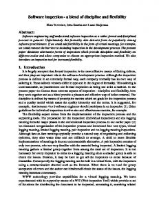
Several climbing systems using electroadhesion technology have been developed to enable wall climbing [5–8]. Inspired by climbing animals, these robots use van der Waals forces of attachment. This dry adhesion is useful for remote monitoring or inspection of concrete pillars or other structures such as bridges and tunnels. The most common type of climbing robots uses vacuum suction cups to adhere to flat and homogenous surfaces, e.g., for automated cleaning of high-rise building facades [9,10]. Guimaraes et al. [11] propose a small, remote-controlled, lightweight climbing machine for walls, ceilings or rounded surfaces. Vacuum forces induced in a central vacuum chamber surrounded by a flexible foam seal, holds the robot to hard surfaces. Leibbrandt et al. [12] present a specific version of vacuum adhesion with a climbing robot for routine inspections of reinforced concrete structures. It generates suction by creating an air vortex in a central tube. Only its wheels need to be in contact with the surface being climbed. This paper discusses a new variation of a climbing robot that employs suction adhesion and is specifically able to move and operate on the surface of the solar power plant’s heat exchanger. Eddy current (ET) inspection is often used to detect corrosion, erosion, cracking and other changes in tubing [13]. Heat exchangers and steam generators, which are used in power plants, have thousands of tubes that have to be kept from leaking. This is especially important in nuclear power plants where reused, contaminated water must be prevented from mixing with freshwater that is returned to the environment. Eddy current testing and related remote field-testing are high-speed inspection methods for such applications. Both electromagnetic methods are applied to thin tubes (up to 3 mm thick), specifically ferromagnetic materials (stainless steel, Inconel, etc.) in the former and nonmagnetic materials (carbon steel) in the latter. The test is performed with a bobbin coil that produces an electromagnetic field in the tube. This enhances the sensitivity of inspection of the inside diameter of a tube where defects are most likely to occur. By using multiple frequencies, 100% of a tube’s wall can be scanned to detect flaws at various depths. When the probe is moved across uneven surfaces, the electromagnetic field is distorted as a function of the size and location of the asperity relative to the probe. This distortion in the magnetic field alters the coil impedance relative to the asperity. This coupling effect of the eddy current probe with the material makes it essential that tubes be properly cleaned and their dimensions are known prior to inspection. The key to reliable detection of the extent and depth of such defects is correct selection of the probe material and precise calibration. Calibration must therefore be done with exactly the same material as that inspected later. Since they are accessible, tubes could be inspected from the inside. This is not possible in the receiver, however. That is why, the use of nondestructive testing (NDT) methods from the outside has been proposed in MAINBOT. This requires a different type of ET sensor. The sensor concept used in [14] (in-service oxide layer measurement in fuel rods) was modified for the inspection of receiver tubes. High frequency and low frequency ET probes were designed to measure coating and tube thickness, respectively (see Figure 2). Many other applications employ ET inspection from the outside surface (railway inspection, turbine and compressor blade inspection [15], etc.).
Robotics 2015, 4
107
(a)
(b)
Figure 2. (a) Conventional ET bobbin coil; (b) ET sensors proposed in MAINBOT. 3. Climbing Robot Design 3.1. Robot Specifications The climbing robot is designed to inspect vertical structures and can be deployed in different areas of the plant. The prototype climbing robot built is intended to inspect the tubes of a central tower CSP plant’s receiver. Figure 3 pictures the architecture of the climbing robot as well as the existing prototype. The climbing robot is moved vertically on the tower by the crane atop the receiver tower. The robot system includes a climbing mechanism that can be synchronized with the crane to bring the robot in the desired position. The robot is attached to the tower by arrays of vacuum suction cups. Four arrays are attached to the robot frame (the outer contact elements) and one array is integrated in the climbing mechanism (the center contact element). Since every climbing action entails aligning every one of the oval suction cups with the tubes of the panels, an optical sensor (tube scanner) scans the profile of the panel to determine the position of the tubes. To implement the climbing robot design effectively, its movement and performance were simulated on a virtual tower model. The undercut of the panels on the receiver tower demands special attention when the inspection system is brought into the start position. The features of the MAINBOT climbing robot are: -
robot weight: ~280 kg robot dimensions: 2.3 m × 1.6 m × 0.8 m high payload (only limited by the crane) obstacle navigation (climbing mechanism) adaptability to different surfaces, material and structures (interchangeable and adjustable contact elements) accurate tool (sensor) positioning thanks to servo controlled motion system fully and semi-automated operation modes with Web UI interface synchronized movement of robot and crane
Robotics 2015, 4
108
Figure 3. Service robot for absorber panel inspection (schematic view; picture of prototype). 3.2. Robot Climbing Mechanism The robot includes a climbing mechanism with variable step size. The load of the robot is borne by the crane atop the tower (or the object being inspected). The robot is secured horizontally by its contact elements to prevent the system from swinging. The robot is in contact with both adjacent panels in order to leave one entire panel free for inspection. The telescopic mechanism makes step width greater than the robot’s height. The climbing kinematics is also used to move sensors. The diagram below illustrates the robot’s climbing procedure (see Figure 4). Arrays of vacuum suction cups at the contact elements establish contact to the tubes of the receiver. The outer elements are in contact with the adjacent panels during inspection. The vacuum grippers are aligned with the tubes automatically in a two-stage contact process. Soft bumpers at the elements ensure collision-free movement of the robot to protect the tube surface (see Figure 5a). The contact with
Robotics 2015, 4
109
the adjacent panels leaves the entire area between the robot and the panel free, thus, allowing inspection by the NDT sensors (see Figure 5b).
Figure 4. Stepping procedure of the climbing robot. The central contact element can move in XYZ-direction relative to the robot frame. The element is in contact during vertical robot movement. A wire sensor measures any potential vertical deviation of the crane position and the vertical robot position, which can arise when their speeds differ. The position signal is used to synchronize the crane and the robot.
(a)
(b)
Figure 5. (a) Contact element of the climbing robot; (b) Working area of the sensor system. The performance of the climbing robot prototype was validated using an indoor mock-up of the receiver panel, which is composed of an array of aluminum tubes. Various tests were performed to validate the contact process, including the alignment method, the adhesion forces and the energy consumed to establish the vacuum.
Robotics 2015, 4
110
Table 1 provides an overview of the maximum adhesion forces of each element in contact with the tube surface as well as the forces without vacuum contact and with contact to a flat surface. The forces without contact result from the minimal inclination angle of the winch rope. When it is moving vertically to the next inspection area, the robot’s central element is in contact with the panel. The robot runs in synchronous mode together with the winch. Figure 6 compares uncontrolled and controlled vertical robot movement. The deviation between the robot’s vertical axis and winch position increases during uncontrolled vertical movement. Reasons for this are different target speeds and the swinging of the robot hanging from the winch. Uncontrolled movement is only possible for small vertical steps and only within the maximum range of deviation allowed. Table 1. Horizontal adhesion forces of the contact elements. Holding Forces [N] without vacuum contact vacuum contact with the tube surface vacuum contact with a flat, homogeneous surface
Top right 55
@ Contact Element Top left Down right Down left 58 62 64
Center 154
209
223
209
214
365
289
305
270
295
405
Figure 6. Comparison of uncontrolled and controlled vertical robot movement.
Robotics 2015, 4
111
The control algorithm implemented compensates for the different speeds of the winch and the robot’s Z-axis. The speed of the robot axis (slave speed) is controlled as a function of the speed of the winch (master speed). Furthermore, any initial deviation is compensated within a short time. Several tests were performed at different speeds, in different directions and under different initial conditions to verify the control algorithm. A typical motion sequence during the inspection of individual tubes is presented in Figure 7. The total time required to inspect one panel area is about 27 min. Since increasing the climbing inspection speed is expected to reduce this time by as much as 50%, most of the individual robot actions were tested on the mockup at higher speeds. Table 2 shows the time durations of individual robot actions and complete receiver inspection, comparing the measured values with the times after optimization.
Figure 7. Robot movement during the inspection of the exchanger tubes. 4. Nondestructive Testing (NDT) of the Receiver Tubes Two techniques are proposed for nondestructive inspection of the panels: visual inspection and eddy current testing. The first is used to assess coating degradation. Eddy current testing has the dual objective of measuring coating thickness and detecting internal corrosion (manifested as a reduction in tube thickness).
Robotics 2015, 4
112 Table 2. Total inspection times of the climbing robot. Robot Operation
Time Duration [s] measured after optimization 300 (estimated) 300 (estimated) 130 70 15 5
Move to panel Remove from panel Move to next area (performing one step) sensor positioning data acquisition (for tube section of 1.5 m): paint layer thickness and internal assessment with ET 50 external assessment with video 30 move to next tubes 10 Inspection of complete GEMASOLAR receiver with 2 sensors in parallel 95 h with 8 sensors in parallel 30 h
25 8 5 50 h 16 h
Tube inspection is quite common in nuclear power plants. Different eddy current sensors (bobbin coils, rotatory coils, etc.) are used to inspect in-service steam generator tubes periodically for degradation. These sensors are inserted in the tube and run along its whole length to detect stress corrosion cracking and other mechanical degradation modes that could cause tube failure. The inspection of fuel rods to measure oxide layers is another nuclear application in which eddy currents deliver the best performance. Specialized sensors are used to inspect them from the external surface. Comprehensive inspection of such components requires a combination of advanced probe technology coupled with versatile instruments and robotic systems controlled by fast computers and remote communication systems. The in-service inspection company and manufacturer of eddy current sensor and data acquisition systems, Tecnatom has contributed its extensive experience and know-how in this field to the MAINBOT project. Visual cameras and eddy current sensors were integrated into the service robot to assess the degradation of the receiver tubes: The coating thickness (µm) is measured by the eddy current testing (ET) to detect diminished heat transfer performance. Furthermore, tube thickness (