Robust Navigation Based on Bistatic Radar and BiSensors for Unmanned Air Systems (UASs) Using Integration of Multiple Sensors Fusion Architecture Yasser M. Madany
Hassan M. Elkamchouchi
Mostafa M. Ahmed
SMIEEE, Comm. and Electro. Depart., Alexandria University, Egypt
[email protected]
SMIEEE, Comm. and Electro. Depart., Alexandria University, Egypt
[email protected]
Comm. and Electronics Depart., Alexandria University, Egypt
[email protected]
Abstract—Unmanned aerial vehicles (UAVs) have become one of the most popular and promising means for both military and civilian posts and academic research areas. Localization of the UAVs and persistent tracking of a UAV have vital importance to provide a UAV with navigation information and help to cope with getting lost permanently. Indeed, inertial navigation system (INS) and global positioning system (GPS) seem to be adequate for navigation of UAVs. However, an alternative augmented navigation system for UAVs should be taken into consideration since INS has accumulated errors and GPS always has the possibility of jamming and satellite signal loss. Unmanned air systems (UASs) are playing increasingly prominent roles in defense programs and strategy around the world. For many of applications to develop into maturity, the reliability of UASs will need to increase, their capabilities will need to be extended further, their ease of use will need to be improved, and their cost will have to come down. In this paper the fusion between the data derived from the magnetometer, rate-gyro, accelerometer, pitot tube, pressure and the GPS is integrated in one system using an extended kalman filter (EKF) which uses a linear error model to estimate the errors in the states for UAV to enhance its performances. The proposed system introduces a robust navigation based on bistatic radar and bi-sensor for UAVs flight dynamics with decreases the faults in operational environment.
I.
INTRODUCTION
The position estimation (location) problem of an object is a research subject that has attracted a lot of interest during the recent years. Several applications on location of expensive computer equipment [1], [2], management of products and transportation [3], [4] are reported in the literature. Localization of UAVs is particularly interesting since they have important industrial applications. In addition, recent advances in electronics have dramatically improved the degree of integration of onboard control systems for UAVs. However, UAV localization is still an issue which requires to be improved. For outdoor applications, GPS provides low errors in location estimation but these errors are significant for UAVs. In addition GPS can only be used outdoor and far enough from buildings or large obstacles otherwise GPS signal become unreliable. Furthermore UAVs require an additional position estimation, to remain operating after GPS
978-1-4799-2035-8/14/$31.00@2014 IEEE
failure. GPS outage has been addressed by combining measurements from GPS and an inertial measurement unit (IMU) [5]–[7]. The inertial data are used as a reference trajectory, and GPS data are applied to update and estimate the state error of such a trajectory. In this paper, a robust navigation system based on bistatic radar and bi-sensor for UAVs has been introduced which can be defined as an artificial system equivalent to the human pilot for detecting and avoiding hazard situations. The proposed system modelling and simulation involves flight testing to collect observation data in order to accurately model the flight dynamics. This involves designing test maneuvers to excite the dynamic response modes and regress the collected flight data into an integrated hypothesized model with multiple sensors fusion architecture. II.
THE SENSORS FUSION ARCHITECTURE
The brain of the UAS is called the flight computer or autopilot. The autopilot, either solely or in combination with other avionics, uses onboard sensors to estimate its current position and orientation, perform flight control by translating flight commands into airframe actuator commands, and in some cases perform payload control such as, pointing a gimbaled camera [8]-[12]. The next subtitles introduce different types of sensors which have been fused in the proposed UAS. A. Magnetometer Sensor The earth’s magnetic field is three dimensional. There is a component that points to magnetic North, but there is also a vertical component. A three axis magnetometer measures the strength of the magnetic field along each of its axes. Magnetometers measure the dot product between the magnetic field vector and the sensitive axis of the magnetometer at particular points. They do not measure any rigid projectile model states directly, and require processing to obtain useful sensor feedback data. They use projectile kinematics differential equations to obtain state estimator of the body orientation Euler roll, pitch, and yaw angles (φ,θ,ψ) [13]-[15]. B. Rate-Gyro A gyro measures rate of rotation around a particular axis. If a gyro is used to measure the rate of rotation around the
0670
aircraft roll axis, it will measure a non-zero value as long as the aircraft is rolling, but measures zero if the roll stops. A gyroscope helps measure or maintains orientation, using the principles of angular momentum and gives an indication of the angular velocity (p, q, r) in the body reference frame [16]. C. Accelerometer Sensor Acceleration transducers (accelerometers) typically employ a proof mass held in place by a compliant suspension. The proof mass moves relative to the case through a distance proportional to the acceleration, when the case of the accelerometer experiences acceleration. The acceleration experienced by the proof mass is converted to a displacement by the springs in the suspension. A three axis accelerometer has the ability to gauge the orientation of a stationary platform relative to the earth’s surface. If the platform happens to be in free fall, the acceleration will be shown to be zero. An accelerometer measures vibration and linear acceleration (Ax, Ay, Az) [17]. D. Pitot Tube Basically, a differential pressure sensor or a pitot tube is used in wind tunnel experiments and on airplanes to measure flow speed. It's a slender tube that has two holes on it. The front hole is placed in the airstream to measure what's called the stagnation pressure. The side hole measures the static pressure. By measuring the difference between these pressures, you get the dynamic pressure, which can be used to calculate airspeed, Vs. On an airplane, the pitot tube can be mounted in a number of ways, including jutting out from the edge of the wing or sticking up from the fuselage [18]. E. Pressure Sensor Pressure is a quantity commonly associated with fluids that is defined as the force per unit area acting on a surface. Pressure acts in a direction normal to the surface of the body to which it is applied. The measurement of pressure has been used to provide indications of the altitude of the aircraft using an absolute pressure sensor. F. Global Positioning System A GPS antenna and receiver are typically used to provide the UAS North–East–Down position and velocity vector in global coordinates. Specifically, an off-the-shelf GPS receiver can usually provide the UAS its latitude, longitude, altitude above mean sea level (MSL), and altitude above ground level (GL), in addition to its three-dimensional inertial velocity vector. These measurements have been converted to local Cartesian coordinates [12], [19]. III.
THE PROPOSED UNMANNED AIR SYSTEM CONFIGURATION MODELLING
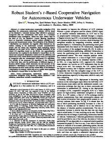
Recently the use of GPS signals as opportunistic bistatic radar signals has become increasingly popular in the radar and navigation communities for remotely sensing the Earth's surface [20]-[21]. A GPS bistatic radar uses two reception antennas: one tracking the direct signal with right-hand circular polarized (RHCP) from the satellite oriented skyward; the other observing the surface-reflected signal with left-hand circular polarized (LHCP) oriented toward the earth, as shown in Fig. 1. In addition, a system comprising two GPS receivers and one satellite transmitter can be thought of as two connect-
978-1-4799-2035-8/14/$31.00@2014 IEEE
ed bistatic radars and satellite motion is used to reach proper resolutions. Then, the concept of bistatic has been investigated for single GPS (direct and reflected signals) and dual GPSs (two receivers and one transmitter). Satellite Transmitter Direct Signal RHCP Range Cells
Specular Reflection Reflected Signal LHCP
GPS Receiver Receiver Height above Specular Point
Figure 1. Single GPS bistatic radar concept.
There are two types of bistatic GPS signals, diffuse and specular. Specular bistatic GPS signals are characterized by an optimal geometry, providing a very powerful reflection. The strength of the specular bistatic returns makes them easy to detect. The drawback, however, is the limited area of the earth’s surface they provide information on. The strength of the specular return depends on the smoothness of the surface. A smooth surface such as water provides much stronger specular returns than a rough surface such as forest. Diffuse bistatic returns are produced by scattering of the GPS signal on the surface of the earth. Diffuse signal returns originate from a much larger area which could potentially provide information over a much larger region than possible by processing just the specular returns. Similarly, the concept of bi-sensor can be applied to IMU. A UAS is a system of components, where the aircraft with its avionics, payload, and radio transponder is only a portion of that system. As a system, the UAS also includes the ground control station and its accompanying user-interface software, antennas, and radio transponders for both aircraft control and payload downlink. UAVs require an additional position estimation, to remain operating after GPS failure. GPS outage has been addressed by combining measurements from GPS and IMU with different sensors fusion. The inertial data are used as a reference trajectory, and GPS data are applied to update and estimate the state error of such a trajectory. The Kalman filter is a well-known method for localization and tracking systems and widely-used method to deal with noisy data and sensor fusion. In addition, internal states of a process cannot always be estimated directly. It is based on two main assumptions, target motion and observation models are linear and, theirs errors and initial estimated probability distribution should be Gaussian. The first assumption is not always true; however variants such as EKF can be used to remain UAVs operating. Fig. 2 shows a simplified block diagram for the proposed UAS with two identical sensors fusion architecture, including state estimation, flight control algorithms, and a mission controller. State estimation consists of fusing a combination of stateobserving sensors and forming an estimate of the vehicle kinematic state. The flight control algorithms automatically manipulate the throttle and aerodynamic control surface actuators to achieve a set of trajectory commands using the kinematic state estimate as feedback. The trajectory
0671
commands are generated by the mission controller, which could be a human operator or a set of algorithms that convert mission objectives into trajectory commands. Magnetometer Rate-Gyro
Pitot Tube
Trajectory Command
Mission Control
Throttle Control Surface Commands
Flight Control (Actuators)
Accelerometer
Pressure Sensors
3. A square spiral trajectory, as a sample of the simulation results is shown in Fig. 4 to demonstrate the UAV position, states estimation, the errors and the 3D position trajectory comparison between true, estimated positions and GPS measurement. From Fig. 4, it was found that the validation and investigation of the proposed model approach have achieved by comparing the estimated UAV tracks delivered by the combination of EKF, ADS, and AHRS with those in the original real world data, where GPS measurements are actually available, so that actual UAV tracks are known. In addition, the performance of the proposed model is sensitive to the trajectory type, so the choice for the method to obtain the states estimation must be selected carefully.
GPS
Measurement
Sensors Fusion Architecture (1)
Sensors Fusion Architecture (2) Mission
Mission Objectives
Trajectory
State Estimates UAS Dynamic Response
Kinematic States
State Estimation (EKF)
Figure 2. The proposed UAS configuration modelling based on bistatic radar with the basic elements in controlling the flight.
IV.
SIMULATION RESULTS
With the rapid developments of micro electro mechanical system (MEMS) IMU and GPS, the integrated attitude determination system (ADS) combined with MEMS IMU and GPS occupies a small volume, consumes low power, and provides high reliability solution, which is suitable for small UAV’s attitude determination. With the availability of the concept of bistatic radar and bi-sensor with multiple sensor fusion such as, gyroscope, accelerometer, magneto-meter, air data sensors, GPS, altimeter, cameras, radar, et al., inexpensive ADS with small size have been manufactured after considerable efforts. The widely used ADS, attitude and heading reference system (AHRS), are composed of a tri-axial gyroscope, accelerometer and magnetometer. Dynamic attitude is obtained from gyroscope by dead reckoning while static attitude is acquired from accelerometer and magnetometer. The key difference between an IMU and an AHRS is the addition of an on-board processing system in an AHRS which provides solved attitude and heading solutions versus an IMU which just delivers sensor data to an additional device that solves the attitude solution. In addition to attitude determination an AHRS may also form part of an INS. A form of non-linear estimation such as an extended kalman filter is typically used to compute the solution from these multiple sources [22]-[24]. The overall architecture of the proposed approach was modeled and validated in Matlab/Simulink® simulation environment. The simulation is used to obtain the performance of the proposed system configuration modelling. The proposed model has been checked for a different trajectory with five various combinations of EKF, ADS, and AHRS to get the performance for each case, as shown in Fig.
978-1-4799-2035-8/14/$31.00@2014 IEEE
Figure 3. The combination of EKF, ADS, and AHRS for states estimation.
V.
CONCLUSIONS
Considering the advantageous aspects of UAVs as presented in this paper, it is certain that UAVs play and will go on playing an indispensable role in the future operational environment. However, eliminating and minimizing their disadvantages is very important for both users and humanity. Proper state estimation is of critical importance on a UAS because it provides the feedback used in all UAS flight and payload control routines. By comparing mission trajectory with the current state estimates, the proposed UAS autopilot uses flight control algorithms to convert trajectory commands such as altitude, speed, and the desired route into aerodynamic surface and throttle commands to remain the UAV operating after GPS and/or sensors measurement failure. The proposed robust navigation system based on bistatic radar and bi-sensor for UAVs using integration of multiple sensors fusion architecture has been introduced, modeled and the simulation results obtained to illustrate the excellence performance agreements with the theoretical model expectation. Relatively, the proposed model achieved minimum errors and continuous operational environment. REFERENCES [1]
[2]
[3]
[4]
J. Yim, C. Park, J. Joo, S. Jeong, “Extended kalman filter to wireless LAN based indoor positioning,” Decis. Support Syst., Elsevier, 45, pp. 960–971, 2008. J. Yim, S. Jeong, K. Gwon, J. Joo, “Improvement of kalman filters for WLAN based indoor tracking,” Expert Syst. Appl., Elsevier, 37(1), pp. 426–433, 2010. C. Röhrig, S. Spieker, “Tracking of transport vehicles for warehouse management using a wireless sensor network,” IEEE/RSJ Inter. Conf. on Intelligent Robots and Systems, Nice, France, pp. 22–26, Sept 2008. C. Röhrig, M. Muller, “Localization of sensor nodes in a wireless sensor network using the nanoLOC TRX transceiver,” IEEE 69th Vehicular Technology Conf., Barcelona, Spain, pp. 26–29, April 2009.
0672
[5]
[6]
[7]
[8]
[9]
[10] [11]
[12]
[13] [14]
J. Wendel, O. Meister, C. Schlaile, G.F. Trommer, “An integrated GPS/MEMS-IMU navigation system for an autonomous helicopter,” Aerosp. Sci. Technol, 10, pp. 527–533, 2006. J. Kim, S. Sukkarieh, S. Wishart, “Real-time navigation, guidance and control of an UAV using low-cost sensors,” Inter. Conf. of Field and Service Robotics (FSR’03), Yamanashi, Japan, pp. 95–100, 2003. P.-J. Bristeau, E. Dorveaux, D. Vissière, N. Petit, “Hardware and software architecture for state estimation on an experimental low-cost small-scaled helicopter,” Control Eng. Pract., 18, pp. 733–746, 2010. S. Temel and N. Unaldi, “Opportunities and Challenges of Terrain Aided Navigation Systems for Aerial Surveillance by Unmanned Aerial Vehicles,” Augmented Vision and Reality, Berlin, Germany, Springer, pp. 1-15, 2013. S. Temel, “Insansiz Hava Araclarinda Bilgisayarla Grafik Algoritmalari Kullanilarak Arazi Verisine Dayali Seyrusefer Sistemi Tasarlanmasi,” MSc. Thesis, Aeronautics and Space Technologies Institute (ASTIN), Turkish Air Force Academy (TUAFA), 2008. M. S. Grewal, L. R. Weil and A. P. Andrews, “Global Positioning Systems, Inertial Navigation, Integration, 2nd Ed.” Wiley, Inc., 2007. J. Carroll, “Vulnerability Assessment of the Transportation Infrastructure Relying on the Global Positioning System,” Technical Report, Volpe National Transportation Systems Center, 2001. M. Melega, S. Lazarus, A. Savvaris, and A. Tsourdos,"GPS/INS integration in a S&A algorithm based on aircraft performances estimation,” 21st Mediterranean Conference on Control & Automation (MED), Crete, Greece, pp. 513-518, June 2013. P. Ripka,"Magnetic sensor and magnetometer", Artech House, 2001. N. Nordkvist and A. K. Sanyal, "Attitude Feedback Tracking with Optimal Attitude State Estimation", American Control Conference, pp.2861-2866, 2010.
[15] R.M. Rogers,"Applied Mathematics in Integrated Navigation Systems", American Instit. of Aeronautics & Astronautics, Inc., 2003. [16] D. Gebre-Egziabher, G. H. Elkaim, J. D. Powell, et al., “a Gyro-free quaternion-based attitude determination system suitable for implementation using low cost sensors,” Position Location and Navigation Symposium, IEEE 2000, pp.185-192, 2000. [17] L. Qin, W. Zhang, H. Zhang, et al., “Attitude measurement system based on micro-silicon accelerometer array,” Chaos, Solitons and Fractals, 29(1), pp.141-147, 2006. [18] R.Carlson,"Accuracy of UAV pitot-static system",UROP-Spring, 2012. [19] M. Melega, S. Lazarus, M. Lone, and A. Savvaris,"Autonomous sense & avoid capabilities based on aircraft performances estimation,” Proceedings of the Institution of Mechanical Engineers, Part G: Journal of Aerospace Engineering, 2013. [20] D. Masters, D. Akos, S. Esterhuizen, and E. Vinande, “Integration of GNSS bistatic radar ranging into an aircraft terrain awareness and warning system,” In Institute of Navigation GNSS, ION, 2005. [21] D. Masters, P. Axelrad, V. Zavorotny, S. J. Katzberg, and F. Lalezari, “A passive gps bistatic radar altimeter for aircraft navigation,” In Institute of Navigation GPS, ION, 2001. [22] A. Kealy, and S. S.Young,"An integrated position and attitude determination system to support real-time, mobile, augmented reality applications,” Journal of GPS, vol. 4, no. 1-2, pp. 12-26,2005. [23] I. H. Makhdoom and S. Y. Qin, “Matlab-based flight control design scheme for UAVs,” in Proc. of the 8th World Congress on Intelligent Control and Automation, pp. 1179–1184, 2010. [24] D. Meola, L. Iannelli, and L. Glielmo,"Flight control system for smallsize unmanned aerial vehicles: design and software-in-the-loop validation,” 21st Mediterranean Conf. on Control & Automation (MED), Crete, Greece, pp. 357-362, June 2013.
UAV Position Roll Angle, deg
GP S Me a s . Es t. P o s .
-200
North, m
UAV Attitude: Roll
40
0
Tr u e P o s . St a r t
-400
Es t. R o l l
20
Tr u e R o l l
0 -20
0
50
100
150
Altitude, above MeanSeaLevel, m
-800 -600
-400
-2 0 0
Pitch Angle, deg
-800
0
East, m 300
GP S Me a s . E s t . Al t
200
Tr u e Al t 0
50
300
350
400
100
150
200
250
300
350
E s t. P i tc h
20
Tru e P i tc h
10 0 -10
0
50
100
150
200
250
300
350
400
Time, s
400
30
GP S Me a s . E s t. S p e e d Tru e S p e e d
20 10
0
50
100
150
200
250
300
350
400
Time, s
UAV Attitude: Yaw
200
YawAngle, deg
Inertial Speed, m/s
Time, s
Ma g n e to m e te r E s t. Ya w Tru e Ya w
0
-2 0 0
0
50
100
150
-5
-5 20 0
40 0
0
Time, s
20 0
40 0
0
Time, s
20 0
40 0
Ve E rror, m/s
Pe E rror, m
Pitc h E rror, deg
-5
0
-5
0
-5 0
20 0
40 0
0
Time, s
20 0
40 0
0
Time, s
20 0
40 0
V d E rror, m/s
A lt E rror, m
-2 00
0
-5
0
-5 0
20 0
Time, s
40 0
0
20 0
Time, s
40 0
0
20 0
4 00
-0 .0 1 20 0
40 0
4 00
0
220
0.0 0 5 0 -0.0 0 5
(b) States estimation errors
-0 .0 1 0
20 0
Time, s
4 00
GPS Meas. Est. Pos. True Pos.
200
-0 .2 0
2 00
4 00
180 160
0 .2 0 .1
140
0
120
-0 .1 -0 .2 0
2 00
4 00
Time, s
0 .0 1
Time, s
400
-0 .1
Time, s
0
0
350
y
0 .1
Time, s
5
0
20 0
0 .0 1
Time, s
5 200
-0 .0 1 0
300
y
0 .2
Time, s
5
0
-0.0 0 5
Time, s 5
5
0
Gyro-y Bias Error, rad/s
0
j
h m s lm
-5
0
Acc el-y Bias Error, m/s2
0
250
Accel Biases
Ac cel-z Bias Error, m/s2
Vn Error, m /s
Pn Error, m
Roll E rror, deg
0
Gyro Biases 0 .0 1 0.0 0 5
A ccel-x Bias E rror, m /s2
Velocity 5
Gyro-x B ias E rror, rad/s
Position 5
Gyro-z Bias Error, rad/s
Attitude 5
200
Time, s
(a) UAV position and states estimation.
Yaw E rror, deg
250
UAV Attitude: Pitch
30 -1 0 0 0
100
200
Time, s
-600
100 200 0 -200
0 .2
-400
0 .1
-600 -800
0
-1000
-0 .1
northm
-0 .2 0
2 00
Time, s
4 00
-1200
-1000
-800
-600
-400
-200
0
eastm
(c) 3D position trajectory comparison between true,estimated positions and GPS measurement.
Figure 4. Square spiral -trajectory with combination of AHRS, EKF and Euler.
978-1-4799-2035-8/14/$31.00@2014 IEEE
200
0673