controller gain is typically set such that the maximum servo valve control signal is obtained for a position error equal to 4-. 5% of the full actuator travel, and this ...
International Journal of Applied Engineering Research ISSN 0973-4562 Volume 11, Number 15 (2016) pp8590-8597 © Research India Publications. http://www.ripublication.com
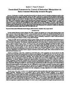
Robust pressure control improves the performance of redundant fly-by-wire hydraulic actuators Giovanni Jacazio and Laura Gastaldi Department of Mechanical and Aerospace Engineering Politecnico di Torino, Italy * Corresponding author architecture entails the force fighting problem. A very important design issue is to guarantee that no conflict originates between the actuators such to impair the flight control system performance. Force fighting can be due different causes: manufacturing tolerances, assembly, performances degradations [17-19], mechanical compliances [20], working conditions, etc. In this scenario a critical problem associated with servo valves is their offset, that can greatly differ from one servo valve to another. The servo valve offset is typically considered as the sum of two contributions: the null bias and the null shift. The null bias is defined, under standard operating conditions, as the difference between electrical null (zero input current) and hydraulic null (zero pressure differential).The typical value of null bias is 3 to 4% of the rated input current. The null shift is a temporary variation of null bias with varying environmental and operating conditions. It may reach 10% of the rated input current. The null shift is not a deterministic effect: two nominally equal servo valves may exhibit different null shifts, and also in the opposite directions. Under an adverse combination of null bias and shift, the resulting total servo valve offset can reach 15% of the rated input current. An unfavorable combination of servo valves offsets can then originate a critical force-fighting condition with adverse effects on the overall system stiffness, resolution and frequency response. Fig.1a shows the total force developed by two servo valve controlled actuators in case of identical offset. Fig. 1b shows the case when opposite offsets of the two controlling servo valves occurs: a dead band is originated in the force/current diagram, which causes a severe performance degradation.
Abstract Aircraft primary flight control surfaces are typically driven by two linear hydraulic actuators accepting the controlled flows from two independent hydraulic systems. When the actuators are part of a fly-by-wire system, actuators flows are controlled by valves, and a key issue is to ensure a pressure matching between the two actuators to prevent force fighting with a resulting loss of stiffness and dynamic performance. Different solutions have been used to minimize the pressure mismatch between two redundant electro hydraulic actuators, but limited use has been done of techniques based on generating compensation signals to reduce the difference between the pressure differentials of the two servo actuators. The advances in microprocessors computing power offer new possibilities that can be exploited to perform a good pressure matching between redundant actuators by using an appropriate control strategy without the need of a complex hydraulic design. This paper first presents a brief survey of the existing architectures of dual redundant electro hydraulic servo actuators, then describes a research activity performed on this subject. An optimal and robust equalization control strategy was devised, capable of minimizing the force fighting between servo actuators while using conventional electro hydraulic servo valves, thereby leading to appreciable weight and cost savings. Keywords: Fly-by-wire systems, equalization techniques, hydraulic actuators, servo valves
INTRODUCTION Fly-by-wire flight control systems use electrical signaling to relay the commands to the flight control actuators [13].Currently the research is moving toward a more electrical aircraft [4] (MAE), but a number of topics must still be faced, including the dependence of performance and life of electrical servo axis and of their transmission on their control parameters [5-6]. So far electro hydraulic servo valves (EHSVs) are the most common devices used to interface with the flight control computers (FCCs) and to modulate the flow to the hydraulic actuators in fly-by-wire systems [7-9]. In general it is well assessed that servo valves [10-14] offer several advantages: relatively limited cost, little weight, very small electrical input power and large chip shear capability (if the valve spool is stuck in one position due to a debris, the pressure differential between the two sides of the control valve spool generates a large force on the spool to break it loose). In order to ensure the necessary redundancy [9], [1516], two actuators are normally used in primary flight controls to drive the same aerodynamic control surface, with each actuator interfacing with one or more FCCs. Redundant
Figure 1: Force-current diagram for two servo actuators controlled by servo valves with a. identical offset, b. opposite offsets
8590
International Journal of Applied Engineering Research ISSN 0973-4562 Volume 11, Number 15 (2016) pp8590-8597 © Research India Publications. http://www.ripublication.com -
Primary flight controls have a very tight requirement for the servo actuator resolution; it depends upon the aircraft category, but most often the angular deflection of the flight control surface is in the range 0.006° - 0.025°. For the case of 60° travel of the flight control surface, the above resolution requirement corresponds to a servo actuator resolution between 0.01% and 0.04% of its full travel. The electronic controller gain is typically set such that the maximum servo valve control signal is obtained for a position error equal to 45% of the full actuator travel, and this stems from the need to provide a suitable frequency response while maintaining an adequate stability margin. As a result, considering a dead band equal to 15% of the maximum servo valve control signal this is reflected into a dead band of 0.6% to 0.75% of full actuator travel, which is about two orders of magnitude greater than the specified resolution. The dead band around the null condition also negatively affects the system frequency response to small amplitude commands introducing excessive phase lag and gain attenuation.An additional critical point created by the dead band of the actuators load force is the reduction of the system stiffness which allows flutter to develop on the flight control surface. It is therefore clear that a flight control actuation system architecture, in which two active servo valve control two servo actuators driving the same flight control surface, is not acceptable for aircraft primary flight control systems. Over the years different design solutions have been worked out for redundant configurations and have been implemented into operational aircraft [3-4]. Different types of architecture of redundant servo actuators system are briefly discussed in the following section, pointing out their pros and cons. Among the different solutions pressure equalization between the two electro hydraulic servo actuators is the most simple one, and theoretically it offers many advantages. However a fine tuned and robust control law is required, which has represented so far a limitation for a wide spread of this architecture. The results of a research activity aimed at defining an optimal and robust equalization technique for redundant actuators will be presented in the paper: a description of the implemented equalization control law and numerical results will be discussed.
-
Single flow control valve.The flows to the two hydraulic actuators are simultaneously controlled by two sections of a single control valve. Equalization between the two electro hydraulicservo actuators. Sensors are introduced to measure the differences between the two servo actuators parameters and appropriate control laws are defined to correct those differences.
Active/standby systems Active/standby systems have been a common solution in many fly-by-wire flight control systems. With this architecture (Figure 2), each actuator receives the controlled flow from an independent servo valve which accepts the electrical signals from FCC. Each servo actuator consists of a linear hydraulic actuator, a flow control valve, a solenoid valve, a shutoff/bypass valve and a control electronics; a position transducer inside the hydraulic actuator provides the feedback signal to the control electronics to close the position control loop. The actuator control electronics generates the control signal to the control valve according to a proper control law, thereby modulating the flow/pressures to the hydraulic actuator as required to respond to the pilot inputs and to the variable loads on the aerodynamic surface.The actuator control electronics also generates an on/off electrical signal (arming signal) to a solenoid valve to enable/disable the actuation system operation.When the solenoid valve is deenergized, or if no pressure is available due to a hydraulic system failure, a shutoff / bypass valve is switched into a position such to close the connection between the ports of the control valve and the hydraulic actuator, and to simultaneously interconnect the two sides of the actuator in order to allow a flow recirculation as a consequence of the movements imposed to the actuator from the other active actuator connected to the same flight control surface. Very often, the fluid recirculating between the two sides of the actuator passes through a restrictor to generate some damping for the actuator. Each of the two identical electro hydraulicservo actuators is hooked to a different aircraft hydraulic system and it is often controlled by two different control lines, thereby leading to a dual hydraulic/quadruplex electrical architecture. With the active/standby architecture one of the two servo actuators is operating while the second one is in the bypass mode. This solution is simple and eliminates the root cause of the dead band and has for instance been used by Airbus for the fly-bywire primary flight control actuators oftheir aircraft. Two main drawbacks are however associated with this architecture. Firstly, the actuators must be overdesigned since under normal operating conditions the active actuator must be capable of driving the maximum aerodynamic load plus the load created by the standby actuator. Secondly, in case of a failure of the hydraulic system providing the pressure supply to the active actuator, a time delay occurs between the onset of hydraulic system failure and the instant in which the standby servo actuator is activated and takes up the control of the aerodynamic surface. During this time delay there is a temporary loss of control of the aerodynamic surface, which does not lead to a flight critical condition since it lasts
TECHNIQUES USED FOR REDUCING MISMATCH BETWEEN REDUNDANT HYDRAULIC ACTUATORS Though generalization is often a risky business, still it is possible to group architectures of redundant servo actuators for flight control systems in the following four categories. Active/standby systems. One actuator connected to the same flight control surface is active, while the second one is in standby.In case the operating actuator fails, the other one is activated and ensures an unabated operation. Reduction of the sensitivity to the control valve offsets.Appropriate actions are taken to reduce the effects of the offsets of the control valve and hence the associated mismatch between the actuator forces.
8591
International Journal of Applied Engineering Research ISSN 0973-4562 Volume 11, Number 15 (2016) pp8590-8597 © Research India Publications. http://www.ripublication.com relatively little, but can anyhow create an unpleasant disturbance during the aircraft flight.
Return
Shutoff / bypass valve
Figure 2: Concept block diagram of a single flow control valvesystem
Shutoff / bypass valve
Solenoid valve Servovalve
Solenoid valve
Servovalve
Supply
Single flow control valve The use of a single flow control valve has been a popular technique for obtaining an even load sharing between two hydraulic actuators driving a common aerodynamic surface. The pressurized fluid flows to the two hydraulic actuators are controlled by a single control valve consisting of long spool sliding inside a sleeve interfacing with the two hydraulic systems and the two actuators [9], [15-16].A very careful and accurate machining of the spool lands allows an excellent matching between the two sections, so that equal pressure differentials are created for the two actuators as a result of a spool displacement away from null, providing that the supply pressures of the two hydraulic systems are equal. With this solution, the movement of the spool is obtained by applying appropriately controlled pressures at its two ends by means of two small servo valves.Each opposite end of the spool carries an integral piston sliding inside a cylinder whose two chambers are connected to the control ports of a servo valve, as it is shown in Figure 3.The position of the main control valve spool is measured by a transducer generating a feedback signal used to close a control valve position loop. The two
Master control valve
Return
Feedback signal
Solenoid valve Valve feedback signal
Control electronics
Supply
Return
Supply
Control electronics
Solenoid valve
Arming signal
Solenoid valve
Return
Control valve
Supply
Control valve
Control signal
Shutoff / bypass valve
Feedback signal
Shutoff / bypass valve
Arming signal
Control signal
Feedback signal
Flight control surface
Reduction of the sensitivity to the control valve offsets Pressure gain softening is another approach to minimize the effect of the servo valve offsets and improving the load sharing between two actuators driving a common flight control surface. A reduction of the pressure gain can be obtained by overcutting the spool lands in order to achieve an open-center valve configuration. This solution is effective in eliminating the dead band of the load force diagram, but it brings about two disadvantages: an average low stiffness due to the low pressure gain and large internal leakages due to the open-center configuration.For these reasons, this solution had limited applications.
Flight control surface
servo valves are of a little size since they only have to control the flows resulting from the displacement of the main control valve spool, and present low pressure gains. High gains are not necessary here because the main control valve position feedback loop does not need to be particularly stiff. The actuators servo loop stiffness is in fact ensured by the high pressure gain of the main control valve. Although this architecture is more complex, it has been widely used in flyby-wire primary flight control systems due its undisputable performance advantages. The primary flight control systems of the Tornado and of the F-18 are examples of application of this architecture. The same design concept of using a single valve for modulating the flows to two hydraulic actuators can be pursued by using a direct drive valve (DDV) whose spool is driven by multiple force motors.The spool position is measured by a transducer that provides the signal necessary to close the spool position feedback loop.Primary flight control actuation systems based on this architecture have been used in the primary flight control systems of some military aircraft such as the Eurofighter.A DDV based architecture has the merits of an overall greater reliability and of lower internal leakages, but the much greater electrical power draw and cost may thwart their use in several applications.Moreover, the lower axial force developed on the spool by the force motors when compared to that developed by hydraulic pressure raises concerns about their ability of shearing offlarge debris that could remain stuck between spool and sleeve [20].
Control signal Control electronics Arming signal
Solenoid valve
Control signal
Valve feedback signal
Control electronics
Arming signal
Feedback signal
Figure 3: Concept block diagram of a single flow control valvesystem
Equalization between the two electro hydraulicservo actuators Pressure equalization is a fourth way to improve the load sharing between two electro hydraulicservo actuators while simply using two servo valves, with each valve controlling the flow to its own actuator [17].This architecture is based upon
8592
International Journal of Applied Engineering Research ISSN 0973-4562 Volume 11, Number 15 (2016) pp8590-8597 © Research India Publications. http://www.ripublication.com sensing the pressure differentials between the two control lines of each actuator, compare the two pressure differentials and inject compensation signals into the servo valves currents such to equalize the actuators pressure differentials (Figure 4). This technique is simple in principle, but its implementation is not an easy task since a careful trade-off must be performed between the need of equalizing the actuators pressure differentials and that to avoid excessive transient uncommanded movements in case of a failure and of the subsequent shutoff after the failure has been recognized. The main areas requiring a careful scrutiny are: definition of the best strategy to change from the system null that existed prior to the failure to the system null after the failure, performance with different supply pressures of the two hydraulic systems, dynamic response and stability of the equalization loop, errors of the pressure measuring devices, maximum authority granted to the equalization loop, failure detection of the differential pressure sensors and corrective actions.
Flight control surface
OPTIMAL CONTROL FOR EQUALIZING PARALLEL HYDRAULIC SERVO ACTUATORS As emphasized before, the purpose of the research activity presented in this paper is to define an optimized solution for achieving an even load sharing between two hydraulic actuators separately controlled by individual electro hydraulicservo valves in order to exploit the positive features of these control devices while minimising the negative effect of their possible offsets. The merits of the solution that was eventually developed are thus: simple system architecture, lower cost, limited transient disturbance following a failure, possibility of operation following a seizure of a valve spool.Though the probability of a seizure of valve spool is considered very low, still system architectures based on a single flow control valve for the two actuators (Figure 3) have a failure of this valve leading to the loss of operation of the relevant flight control surface. Controlling the actuator flows with two different control valves offers a greater survivability to the flight control system.The concept schematic for the system under study is therefore the one shown in Figure 4. In order to define the general architecture of a control law aimed at equalizing the forces developed by two actuators controlled by EHSV it is convenient to refer to a linear model of the system; the actual values of the control parameters were then be fine tuned with the use of a non-linear model. This was also used for evaluating the system performance under normal operating, degraded and failure conditions. The block diagram of the linearized mathematical model of the system is illustrated in Figure 5.The input command xC is compared to the position feedback z to generate the position error e which is processed by a control law with a transfer function G1(s) to provide the control signals to the two servo actuators.The control signals (equal for both servo actuators) are modified by the equalization signal h, which is subtracted to the control signal of servo actuator 1 and added to the control signal of servo actuator 2; the modified control signals are then fed to digital-to-analogue converters to generate the input signals to the servoamplifiers with a gain GA generating the controlled currents i1 and i2 to the servo valves.The offsets of the two servo valves are represented in the block diagram by disturbance currents id1 and id2, which are added to the actual currents i1 and i2.Therefore, the two servo valves will behave in response to equivalent currents iV1 = i1+ id1 and iV2 = i2+id2.The remaining portion of the forward path of the control loop is the usual block diagram of a hydraulic servo actuator; GV(s) is the transfer function of the servo valve dynamics, GQand GP the servo valves flow and pressure gains, C the hydraulic capacitance of each actuator chamber, with the actuator assumed at mid position, kL the internal leakage coefficient, A the actuator area, k the stiffness of the actuator attachment point to the underlying structure, cV the external damping coefficient, m the total mass of the moving parts reflected to the actuators linear output.In the same block diagram δp1and δp2 are the pressure differentials across the two sides of actuators 1 and 2, F1 and F2 the corresponding actuator forces, R the load force, y the actuators linear displacement. The transfer function H(s) of the feedback is that of the demodulator filtering the electrical signal provided by the actuators position transducer, which normally consists of
dp sensor
Servovalve
Return
Control electronics
Supply
Return
Supply
Control electronics
Solenoid valve
Arming signal
Solenoid valve
Control signal
Servovalve
d p signal
Shutoff / bypass valve
Feedback signal
Shutoff / bypass valve
Arming signal
Control signal
d p signal
Feedback signal
dp sensor
Figure 4Concept block diagram of two electro hydraulicservo actuators with individual servo valves (EHSVs) and differential pressure equalization
Concerns about these design issues have been the main reason for a very limited application of this type of architecture to fly-by-wire flight control systems.A partial application of this architecture is found in the primary flight controls of the B2.The primary flight control servo actuators of this aircraft actually have their flows controlled by separate DDVs and differential pressure sensors are used by each servo actuator to provide a dynamic pressure feedback for improved dynamic performance.In addition, the signals of the two differential pressure sensors are compared with each other to create compensation signals to the two DDVs and reach a better load sharing between the actuators.DDVs, however, exhibit a much lower offset than EHSVs, therefore, the equalization issue is much less critical than with EHSVs.
8593
International Journal of Applied Engineering Research ISSN 0973-4562 Volume 11, Number 15 (2016) pp8590-8597 © Research India Publications. http://www.ripublication.com injected into the summing points of the forward paths of the two servo actuators control loops. To better understand the rationale behind the selection of the control law outlined above, it is convenient to consider a simplified case of a system in which the control transfer function G1(s) is a pure gain K1, the equalization transfer function He(s) consists only of a proportional gain KPC, and the system is in a stationary condition.For these simplified conditions, the two pressure differentials δp1and δp2 are given by expressions (1) and (2), where e is the servo actuators position error and K’L = GQ/GP is the ratio between servo valve flow and pressure gains.
anLVDT because of its robustness. The two pressure differentialsδp1 and δp2are measured by differential pressure transducers also consisting of LVDTs measuring the displacement of a spring centered cylinder subjected to the pressure differential.The output signal of each of these transducers is therefore demodulated by a filter with a transfer function HP(s).The difference between the two pressure differential signals is then fed to the equalization control law that is indicated in the block diagram of Figure 5 with the transfer function He(s), which is actually a complex function as it is shown in the diagram of Figure 6. The difference δp12= δp1-δp2between the two pressure differential signals first passes through an activation block that is commanded by the enable/disable control logic. In order for the equalization function to be activated, both servo actuators must operate
p1
p2
K1GQG A kL
K L'
K1GQG A kL
K L'
GQ e
k L K L' G AGQ K PC
1 id1 GQid 2
(1)
K L'
k L K L' G AGQ K PC
2
GQid1 GQ
k L K L' G AGQ K PC
1 id 2
K L'
k L K L' G AGQ K PC
2
kL
e kL
(2)
For the worst case of two servo valves with opposite offsets, id1 =-id2=id0, Eqs. (1) and (2) become: p1 p2
K1GQG A kL
K L'
K1GQ G A kL
K L'
e e
id 0 1 / GQ k L
K L'
2G A K PC
id 0 1 / GQ k L
K L'
2G A K PC
(3) (4)
The flow gain GQ is a parameter that is selected as a function of the actuation speed to be developed by the actuator, therefore, should no equalization be present (KPC= 0), the only possible way for reducing the difference between δp1 and δp2 is to increase the internal leakage (greater kL) or reduce the pressure gain GP.However, both these ways lead to a reduction of the value of the coefficient multiplying the servo loop error e, which implies a reduction of the servo actuator stiffness, since a greater error is necessary to obtain the same pressure differential.Introducing the pressure equalization (KPC> 0) brings about a reduction of the effect of the offset current id0 on the pressure differentials.The difference between δp1and δp2thus decreases with increasing the value of KPC, but this process cannot continue above a certain limit for it would lead to an instability of the pressure equalization loop.However, it must be considered that the servo valve offsets are the result of different contributions, as it was outlined at the beginning of this paper.Some contributions (null bias and null shift with temperature) are steady-state or quasi-steady-state factors and their effect can thus be recovered by introducing a low gain integrator (KIC in the block diagram of Figure 6), that eventually develops a signal such to compensate these contributions to the servo valve offsets.Since the maximum null bias is about 4% of the rated servo valve current, and the maximum null shift with temperature can take another 4% of rated servo valve current, the saturation limit KICM of the block diagram of Figure 6 can be set such to correspond to 8% of the rated servo valve current.However, in case the signal of one of the two pressure
Figure 5: System block diagram
Figure 6: Block diagram of the equalization control law
If both switches signals are "on", an enable signal is sent to the activation block that transfers the δp1-2 signal to the following blocks; on the contrary, the output of the activation block is equal to zero. The δp1-2 signal is processed by a modified PI controller in which the gain KIC of the integral part of the controller is varied with time when the equalization logic is activated, starting from an initial large value at switchon to a smaller one after the initial equalization transient has settled. The integrator output signal is saturated to max/ minvalues; the saturation limits are enabled if both pressure switches signals are "on"; on the contrary they are set to zero.The output signals hI and hP from the integral and proportional controllers are summed up, the resulting equalization signal h is saturated to a max/min limit and
8594
International Journal of Applied Engineering Research ISSN 0973-4562 Volume 11, Number 15 (2016) pp8590-8597 © Research India Publications. http://www.ripublication.com switches is "off", the saturation limit KICMis set to zero to fully disable the equalization logic. At the same time, the saturation limit hM of the entire control law can be set to 15% of the rated servo valve current, which is the maximum possible offset under normal servo valve operation. The rationale for this control law is to use the integral control for compensating the steady-state offsets, while using the proportional control only for compensating the rapid variation of servo valve offsets, such as those originated by variations of the return pressure resulting from variable return flows.Since the proportional control has to compensate only a fraction of the servo valve offset, it can be kept lower than it would be required for entire offset compensation, and the equalization loop stability can be maintained while minimizing the residual difference between the two pressure differentials. The gain KIC of the integrator must be kept low to prevent an adverse effect on the stability of the equalization loop, but this may have a negative factor at the start-up when the equalization logic is activated, since it would lead to a long settling time.The value of the integrator gain is thus initially set high and equal to 10 times its normal value and is reduced to its normal value as the difference δp1-δp2is reduced to a value equal to 20% of the supply pressure. From then on, the integrator gain remains constant at that value, no matter of the variations of δp1-δp2.This technique allows a large reduction of the initial settling time without affecting the equalization loop stability.
results of these simulations were used as a benchmark to evaluate how the differential pressure equalization technique could mitigate the effects of servo valves offsets.Then, simulations were run for the case of two actuators controlled by servo valves with offsets equal to 15% of the rated current, but in the opposite direction,which is the most adverse combination under normal operating conditions.These simulations were performed with and without differential pressure equalization, which allowed to evaluate the merit of the equalization algorithm. The system dynamic response was determined for significant inputs representative of the aircraft flight envelope, as it will be outlined in the following. The simulation campaign clearly showed the ability of the pressure differential equalization technique in improving the system dynamic performance. Once the control parameters were properly tuned, the dynamic behaviour of a system comprised of two actuators controlled by EHSVs with large opposite offsets became very close to that of an ideal system with servo valves with zero offset. A summary of the results is outlined hereunder. Autopilot adjustments This condition is described by the response to a sinusoidal command of ±0.1 mm at a frequency of 0.2 Hz. Figure 7 shows time versus actuator position. Three curves are plotted: the ideal case of zero offset and the cases of maximum opposite offsets with and without differential pressure equalization.The diagram clearly shows that a non-equalized system is almost non responding to the inputs, while the implementation of the pressure equalizing control defined in this research makes the system performance almost equal to the ideal case of servo valves with zero offsets.
ASSESSMENT OF THE EQUALIZATION CONTROL STRATEGY The merits of the equalization control technique described in the previous paragraph have been assessed with reference to a typical fly-by-wire system for the control and actuation of a primary flight control surface of a medium-size aircraft.The system consists of two microprocessor controlled electro hydraulicservo actuators with the main characteristics listed in Table I: Table 1: Characteristics of the fly-by-wire system Supply pressure Return pressure Actuator stroke Maximum load No-load speed Total system inertia reflected to actuator linear output Stiffness of the actuator attachment point LVDTs excitation frequency Microprocessor recursion rate Microprocessor computation time Analogue/digital converters resolution
28 MPa 0.5 MPa 100 mm 25000 N 100 mm/s 90 kg 4x10⁷ N/m 3 kHz 400 Hz 1 ms 12 bit
Figure 7: Time response to a sinusoidal command of ±0.1 mm amplitude at a frequency of 0.2 Hza) Zero offset; b) Max opposite offset without equalization; c) Max opposite offset with equalization (curves a and c are superimposed)
In order to assess the merits of the differential pressure equalization strategy, a very accurate mathematical model of the system was prepared and an extensive simulation campaign was performed.Firstly, simulations were run for the ideal case of two servo actuators supplied with identical pressures and controlled by zero offset servo valves; the
8595
International Journal of Applied Engineering Research ISSN 0973-4562 Volume 11, Number 15 (2016) pp8590-8597 © Research India Publications. http://www.ripublication.com
Figure 8: Frequency responseto a sinusoidal command of ±2 mm amplitude a) Zero offset; b) Max opposite offset without equalization; c) Max opposite offset with equalization
Figure 10: Response to half-sine load a) Zero offset; b) Max opposite offset without equalization; c) Max opposite offset with equalization
Pilot commands This condition is best described by the frequency response under commands of ±2 mm amplitude.Figure 8 shows the frequency response diagram in the range of interest for primary flight controls
Windshear This condition can occur when the aircraft is flying in proximity of ground and can be described by subjecting the servo actuator to a half-sine load variation occurring in 0.5 s with a peak of 10000 N. Figure 10 shows the dynamic stiffness diagram.
CONCLUSION An equalization technique was presented that minimises the negative effects of servo valves offsets on the hysteresis and dynamic response of dual redundant electro hydraulicservo actuators used in primary flight control systems.By using signals provided by two pressure differential transducers it is possible to perform an effective compensation of variable servo valves offsets and implement a suitable control strategy permitting a good load sharing between two electro hydraulicservo actuators acting on a flight control surface.This offers the possibility of developing simpler configurations of the servo actuators with ensuing lower weight and costs, and increased reliability. An accurate analytical model was prepared and simulations were run for cases representatives of significant flight conditions that showed the merits of the pressure differential equalization control algorithm.
Figure 9: Dynamic stiffness a) Zero offset; b) Maximum opposite offset without equalization; c) Maximum opposite offset with equalization
NOMENCLATURES A actuator area A/D analogue/digital converter C actuator chamber hydraulic capacitance cV external damping coefficient D/A digital/analogue converter e position error F actuator force GA gain GI(s) position control law transfer function GP pressure gain GQ flow gain GV(s) servo valve dynamics transfer function H(s) feedback position transducer gain HP(s) position transducer transfer function He(s) equalisation control law h equalization signal hI integral controller output hM equalisation signal saturation hP proportional controller output
Aircraft flight subjected to gusts The system response to this condition is represented by the dynamic stiffness under a fluctuating load of ±3000 N amplitude. Figure 9 shows the dynamic stiffness diagram.
8596
International Journal of Applied Engineering Research ISSN 0973-4562 Volume 11, Number 15 (2016) pp8590-8597 © Research India Publications. http://www.ripublication.com KIC KICM K’L KPC k kL i id iV m R s xC y z dp T0
control integral contribution of the equalisation law integral contribution saturation limitin the equalisation law ratio between servo valve flow and pressure gains. control derivative contribution of the equalisation law actuator stiffness internal leakage coefficient servo valve controlled current disturbance current equivalent current moving part total mass external force Laplace variable position input command actuator linear displacement position feedback actuator chambers pressure differential initial temperature
[10]
[11]
[12]
[13]
[14] REFERENCES [1] [2]
[3]
[4]
[5]
[6]
[7]
[8]
[9]
Schmitt, V.R., Morris, J.W., Jenney, G.D., (1998) Fly-by-Wire ( SAE) Pastorelli, S., Battezzato, A., Mattiazzo, G. (2008) Fly-by-wire control of a helicopter: Multibody main rotor model, 26th Congress of Int. Council of the Aeronautical Sciences, ICAS 2008 Martinez-Val, R., Perez, E., (2009) Aeronautics and astronautics: recent progress and future trends. ProcIMechE- Part C J. of Mech Eng. Science, vol. 223 n. 1-2, p 2767-2820 Van den Bossche, D., (2006) The A380 flight control electrohydrostatic actuators, achievements and lessons learnt. ICAS-Secretariat - 25th Cong. Int. Council of the Aeronautical Sciences. Mauro, S., Pastorelli, S., Mohtar, T., (2014), Sensitivity analysis of the transmission chain of a horizontal machining tool axis to design and control parameters, In: Advances in Mechanical Engineering, 2014, DOI: 10.1155/2014/169064 Mauro, S., Pastorelli, S., Johnston, E., (2015), Influence of controller parameters on the life of ball screw feed drives, Advances in Mechanical Engineering, 7 (8), pp. 1-11. DOI: 10.1177/1687814015599728 Wang, L., Maré, J.C., (2014) A force equalization controller for active/active redundant actuation system involving servo-hydraulic and electromechanical technologies Proc. IMechE, Part G: J. Aeros. Eng, vol. 228, n.10, p.1768-1787 Di Rito, G., Denti, E., Galatolo R., (2008) Development and experimental validation of realtime executable models of primary fly-by-wire actuators. ProcIMechE Part I J Syst& Control Eng, vol. 222, n.6, p 523-542 Harschburger, H.E. (1983), Development of Redundant Flight Control Actuation Systems for the F/A-18 Strike Fighter. SAE paper 831484
[15]
[16] [17]
[18]
[19]
[20]
8597
Sorli, M., Gastaldi, L. (2009) Thermic Influence on the Dynamics of Pneumatic Servosystems. In: Journal of Dynamic Systems, Measurement And Control, vol. 131, pp. 1-5. Gastaldi, L., Sorli, M., Pastorelli, S. Static and dynamic experimental investigation of a pneumatic open loop proportional valve Experimental techniques. In press DOI: 10.1007/s40799-016-01425 Jacazio, G., Gastaldi, L., Balossini, G., Magnani, A. (2013) Hydraulic actuation system with active control for the lateral suspensions of high speed trains. In: International Journal of Heavy Vehicle Systems, vol. 20 n. 3, pp. 236-252. Jacazio, G., Gastaldi, L., Balossini, G., Magnani, A. (2009) An actively controlled hydraulic carbody centering system for the lateral suspensions of high speed trains In: ASME Dynamic Systems and Control Conference, DSCC2009 Sorli M., Figliolini G., Pastorelli S., Rea P. (2005) Experimental identification and validation of a pneumatic positioning servo-system. Power Transmission and Motion Control, PTMC 2005, pp. 365-378. Straub, H.H., Creswell, R., (1991) The Boeing 747400 upper rudder control system with triple tandem valve, SAE paper 912133 Raymond, E.T., Chenoweth, C.C., (1992) Aircraft Flight Control Actuation System Design. SAE paper Wang, S.P., Cui, M.S., Shi, J., Kang, M., (2005) Performance degradation and reliability analysis for redundant actuation system, Chin. J. Aeronautics, vol. 18, n. 4, p 359-365 Jacazio, G., Pastorelli, S., Sorli, M., (2008) A prognostics model for detecting the irreversibility margin of non-reversible electromechanical actuators, Int. Conf. on Prognostics and Health Management, PHM 2008, Denver; United States art. N. 4711457 Karpenko, M., Sepehri, N., (2009) Hardware-in-theloop simulator for research on fault tolerant control of electro hydraulic actuators in a flight control application, Mechatronics, vol. 19, n. 7, p. 1067-1077 Di Rito, G., Galatolo, R., (2012) Experimental assessment of the dynamic stiffness of a fault-tolerant fly-by-wire hydraulic actuator. technologies Proc. IMechE, Part G: J. Aerospace Eng. Vol. 226, n .6, p.679-90.