A VME crate interconnect architecture has been developed for the Data Acquisition System of the KLOE. High Energy Physics experiment [1], based at INFN.
ROCK Manager: the DAQ Chain Controller of the KLOE Experiment A. Aloisio, S. Cavaliere, F. Cevenini, L. Merola Dipartimento di Scienze Fisiche, Università degli Studi di Napoli "Federico II" I.N.F.N. Sezione di Napoli, Mostra d'Oltremare - Pad. 20 - 80125 Napoli - ITALY and D.J. Fiore I.N.F.N. Sezione di Napoli, Mostra d'Oltremare - Pad. 20 80125 Napoli - ITALY
Abstract A VME crate interconnect architecture has been developed for the Data Acquisition System of the KLOE High Energy Physics experiment [1], based at INFN Laboratories in Frascati, Italy. A chain controller (ROCK Manager) can link up to 8 VME crates using a custom cable-bus. The bus protocol (Cbus) has been optimized for random-length block transfers. Data is transmitted isochronously at 10 MHz (40 Mbyte/s) using TTL differential logic. Each transaction on the Cbus is labeled by an event number, which allows the chain controller to ask for a specific data frame. Sub-event building is obtained collecting the data frames available for the requested event from all the devices on the Cbus. The chain controller has been designed around 3K and 4K family XILINX FPGAs. Dual port FIFO banks are used to decouple the VME and the Cbus data traffic. A preliminary version of the board is presented and test results are briefly discussed.
Each ROCK in the chain performs crate level readout, gathering data from slaves on an event number basis. They build data frames consisting of an event number, slave data and a parity word. In the same fashion, the ROCK Manager performs chain level read-out, collecting on the Cbus the data frames belonging to a given event number from all the ROCK boards. This architecture permits true event-driven performances by transferring the most time consuming operations – such as the data framing and the subevent assembly – to the hardware and to the protocols. S ub -Sy ste m Cr ate s L a st ROCK
C P U
S L A V E
C P U
S L A V E
S R LO VME / A C AUX V EK VME
. . .
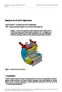
I. THE CHAIN LAYOUT The DAQ System of the KLOE experiment adopts a modular structure of VME crates tied by a vertical connection. This chain (Fig. 1) houses up to 8 crates, each with a VME master, 16 slave boards and a local read out controller, named ROCK [2]. The Cbus links all the ROCK boards to a chain controller - the ROCK Manager. The whole chain is an event-driven environment where all the DAQ slave boards and the controllers share the same trigger pulses. When a trigger is generated, slave boards perform data conversion, label the acquired data with the respective event number, and then push the frame into a data queue. Controllers store the event number in a trigger queue. They proceed to read out the slave boards on an event-by-event basis, retrieving the event number to be processed from the trigger queue.
S R L O VME / A C AUX V EK VME
C SL PA U VE
C SL P AV UE
C B u s
C P U
VMETRIGGER
SUPER VISOR
Trigger
S R L O VME / A C AUX V EK VME
S VME L A VME / V AUX E
R O C K
C P U
S P E E D I/O
H I G H
RM A O NA C G VME K ER VME
Cbus Link to the Event Builder
Fig. 1. Chain layout
Fig. 2. Board layout
II. THE ROCK MANAGER BOARD The ROCK Manager is a VME double height slave board (Fig. 2) with A32/D08(O), D16, D32 and D32:BLT transfer capabilities. It is master on the Cbus, where it performs data readout from each of the ROCK boards in the chain. The ROCK Manager block diagram is shown in Fig. 3. The board is divided into 4 main sections: VME and Cbus interface, a dual port FIFO bank, and a microcontroller. Most of the logic is implemented in XILINX FPGA parts: the VME interface and the microcontroller HUB in two XC3142A; the Cbus interface (RMAN) in a XC4005E. The FIFO bank is 32K x 32 bit words deep. The Cbus architecture allows ringlets to be implemented with distances up to 10 m and up to 8 boards which can be read out by the chain controller in an event driven / token passing fashion. The ROCK Manager starts a transaction by broadcasting the event number to be acquired and then sends out a token, which enables the closest ROCK in the chain. The Cbus interface of the responding ROCK reads from its Data FIFO bank the current event number and compares it with the value requested by the ROCK Manager. If they match, the entire frame for the requested event is retrieved and transmitted to the Manager. Data is transferred to the Cbus at 10 MHz in an isochronous manner. After this ROCK ends its frame with a parity word,
it then gets off of the Cbus and passes a token to the next ROCK in the ringlet. As soon as the next ROCK in the chain receives the token it goes through the same process as the first until the last ROCK in the chain is reached. At this point the last ROCK in the chain will send its frame of data with an endof-chain-frame bit (EOCF) driven low after its last data word is transferred. The ROCK Manager receives EOCF and terminates the data cycle. Each of the ROCKs senses this end-of-cycle and moves toward their idle state. EOCF has also another function: the last ROCK in the chain (in control of EOCF), will not release EOCF until it sees that each of the preceding ROCKs in the chain have all returned to their idle state and are ready to start a new transaction. This is accomplished by using the token passing lines as a means to pass a “done and ready” signal up the chain to the last ROCK. The ROCK Manger can then, if there is an event number pending, start the whole process over again. In this way there is a sort of handshaking between end-of-superframe and start-of-super-frame between all of the ROCKs in the chain and the ROCK Manager. In the case of an event number mismatch at ROCK readout, the Manager will flag an error condition on the Cbus. The ROCK Manager arranges the data into its dual port FIFO bank in a frame by frame manner. Each frame begins with a start-of-super-frame word (SOSF) containing the event number and the chain address.
Fig. 3. Block diagram
This is then followed by the ROCK frames, each containing its own event number, data words and parity word. The data structure is ended with an End-of-SuperFrame word (EOSF), containing the total word count of the super-frame and parity verification bit for each of the ROCKs that responded with data. ROCKs without data for a specific frame did not transfer any data and thus that super-frame does not contain anything corresponding to that particular ROCK's crate address. It is also possible to have an empty super-frame at the ROCK Manager level (none of the ROCKs in the chain had any data for that specific event number). This would consist of only a SOSF word, followed by an EOSF word. The Manager also performs a parity check on each of the ROCK data frames, flagging an individual error bit per ROCK, as well as an overall error condition if needed. To check for correct configuration and installation of the chain, and for general purpose testing, a "Ring-test" can be performed. During a Ring-test, the ROCK Manager broadcasts to all of the ROCKs, requesting their crate identities. The ROCK Manager then proceeds to write into the data FIFO a SOSF word containing its chain address. Each ROCK board will then transmit its crate address in the same fashion as a data transfer. The ROCK Manager then writes an EOSF word, containing the total word count (the number of enabled crates in the chain), into the FIFO for future inspection. In this way, the system configuration identity and chain integrity can be verified.
III - TEST RESULTS The final version of the ROCK Manager board is presently under test in Naples. The board’s VME interface has been fine-tuned to exceed the 10 MHz data transfer rate in block transfer. A new generation of TTL bus drivers [3] has been also adopted to achieve an incident wave switching behavior on the VME backplane The on-board microcontroller (TMS370) performs a real-time monitoring of the board performances during BLTs on the VME and controls the temperature in different sections of the PCB. Monitored data can be displayed on a console terminal via a RS232 interface or can be read by the VME. To evaluate all the ROCK Manager features in a real environment, we have tested a fully loaded Cbus ringlet, with 8 ROCK boards and a total cable length up to 15m. We are now involved in the KLOE DAQ System integration and testing at the Frascati Laboratories, where the experiment is expected to start taking data in 1998.
V - REFERENCES [1] The KLOE Collaboration, " KLOE A general purpose detector for DAΦNE", LNF - 92/019 (IR). [2] A. Aloisio et al. , "ROCK: The Readout Controller For The KLOE Experiment", IEEE Trans. On Nucl. Science, 43, 1, 167(1996) [3] ETL Specification P2/Draft 0.4a VITA, 1993