ROSUnitySim: Development and Experimentation of a Real-time Simulator for Multi-UAV Local Planning
Journal Title XX(X):1–14 c The Author(s) 2015 ⃝ Reprints and permission: sagepub.co.uk/journalsPermissions.nav DOI: 10.1177/ToBeAssigned www.sagepub.com/
Yuchao Hu, Wei Meng
Abstract In this paper, we present a novel real-time 3D simulation system, ROSUnitySim, for miniature unmanned aerial vehicles (UAVs) local planning in cluttered environments. Different from commonly used simulation systems in robotic research, e.g., USARSim, Gazebo, etc., in this work, our development is based on robot operation system (ROS) and with a different game engine, Unity3D. Compared with Unreal Engine, which is used in USARSim, Unity3D is much easier for entry level developers and has more users in industry. On the other hand, as we know, ROS can provide clear software structure and simultaneous operation between hardware devices for actual UAVs. By developing data transmitting interface, communication module and detailed environment and sensor modeling techniques, we have successfully glued ROS and Unity3D together for real-time UAV simulations. Another keypoint of our work is that we propose an efficient multi-UAV simulation structure and successfully simulate multiple UAVs, which is a challenging task, running 40-Hz LIDAR (Light Detection And Ranging) sensing and communications in complex environments. The simulator structure is almost the same with real flight tests. Hence, by using the developed simulation system, we can easily verify developed flight control and navigation algorithms and save substantial effort in flight tests. Keywords Unity3D, Simulator, Unmanned Aerial Vehicle, Navigation, Guidance, Robot Operating System
1
Introduction
Recently, small scale UAVs have recently gained great interest and attention from the academic research groups worldwide because of their great potential in both military and civil applications and many groups have constructed their own UAV platforms 1–5 . Especially, navigation and guidance of UAVs in GPS-denied environments is a still challenging task 6 . Nevertheless, generally speaking, the implementation of UAVs is costly and time consuming. Simulation technologies have been widely used by academic research as a cost-effective way to accelerate processing procedures. They are especially important in the case of UAV development due to the complexity involved in outdoor environments and network communications. Therefore, simulation is an effective way to detect and prevent unnecessary Prepared using sagej.cls [Version: 2013/07/26 v1.00]
malfunctions of hardware, software and automatic flight control systems 1 . Simulation technologies can provide great help to verify the algorithms and identify potential problems before flight tests and to make the physical implementation smoothly and successfully 7;8 . Some well-known recent works have demonstrated the capabilities of 3D simulations, such as OpenSim 9 , Virtual Robot Experimentation Platform (V-REP) 10 , Delta3D 11 , USARSim 12 and Gazebo 13 etc.. OpenSim is one of the earliest attempts for 3D robotic simulator in 2001. It is a 3D simulator for autonomous robots that uses OpenGL for real-time rendering of
Temasek Laboratories, National University of Singapore Corresponding author: Wei Meng, Temasek Laboratories, T-Lab Building, 5A, Engineering Drive 1, Singapore 117411 Email:
[email protected]
2
the robot environment. But the development is no longer active since October 2008 and also it is not good at real-time rendering of robot environments. V-REP is a commercial product and not opensource 10 . Gazebo is a mature and good opensource simulator but it is developed and supported mostly on Linux and not meant for hybrid simulation 13 . To further address the challenges of hybrid simulation, the Unified System for Automation and Robotics Simulator (USARSim), a high-fidelity simulation tool based on Unreal technology gained more researchers’ attention, as it represents robot automation and behavior, as well as renders user interface elements precisely 12 . However, USARSim based simulation tools have not been updated regularly recently. According to our experience, the available simulation systems are not suitable for multi-UAV real-time tests, especially when the 3D environments are of large-scale and complex. As there are many 3D simulators available as stated above, why we still need to develop a new UAV simulation system? The main reason is that the most of the open-source simulation systems are difficult to handle multiple UAVs simultaneously sensing in complex and high fidelity environments. In addition, it is hard to modify the developments in USARSim. Another reason is that for industrial applications, it is required to develop a complete simulation system, including environment sensing modeling, flight control and navigation algorithms. The UAVs are expected to cooperatively and autonomously operate in GPS-denied foliage or urban environments. Light Detection and Ranging (LIDAR) based simultaneous localization and mapping (SLAM) algorithm needs to be simulated in real-time. According to our knowledge, the most of the simulation systems are not ‘real’ enough. Firstly, the environments, especially, the collision level of the trees and buildings needs to be modeled as real as possible. Secondly, UAV sensors such as LIDAR, camera, are required to be modeled as real and need to run in a highfrequency level in a dense and harsh environment. In this paper, a novel hybrid 3D simulator is developed based on Robot Operating System (ROS) and a game engine, Unity3D. ROS 14 is an open-source framework designed to provide an abstraction layer to complex robotic hardware and software configuration. It provides libraries Prepared using sagej.cls
Journal Title XX(X)
and tools to help software developers create robot applications and has found wide use in both industry and academia. Gazebo which was mentioned above also origins from the ROS. Unity3D is a more flexible and powerful development platform for creating multiplatform 3D and 2D games and interactive experiences. This game engine which supports almost every platforms is chosen to be the simulation server. Besides game developments, Unity3D could also be employed by academic research 15 . It has been developed as simulators in geographic information systems 16 , the communication system for Moon base simulated scenario, and wind energy development 17 . These implications prove that Unity3D can also be used in academic area with vivid and highly interactive performance. The main reason of choosing Unity3D as the visualization tool is that it is easier for entry-level researchers to develop their UAV applications, especially, to build the real-time sensor models, physical models, etc. In addition, since the programming language for Unity3D is C#, it is easier for the researchers to understand and further development. The main contribution of this paper is that we have developed an application driven multiUAV simulator based on ROS and Unity3D. To the best of our knowledge, our work is the first one to involve the Unity3D technique to the UAV sensing and planning simulation research. Specially, we focus on a novel and effect way to simulate multiple UAVs simultaneously. In our work, the interface between the ROS and the Unity3D has been developed based on TCP/IP protocol. LIDAR sensor, which is one of the most popular sensors used in GPS-denied environments and the key component for SLAM algorithm is modeled in details in the Unity3D script. Environment modeling including trees, terrain, buildings, etc. are also developed and will be introduced in our simulation technique section. The preliminary version of our simulator has been presented in 18 . In this earlier work, we gave a brief description of the structure of the simulator: ROSUnitySim. In the current version of the work, we have made extensive extensions and new
In this work, we focus on sensor modeling, local planning in GPS-denied environments. GPS is not perfectly carried out by our simulator.
Smith and Wittkopf
3
contributions: (1) The structure of the simulator has been improved to support efficient multi-UAV simulations. (2) The detailed technical issues, such as communication protocol, client/server structure, the interface between the ROS and the Unity3D have been added. (3) Performance analysis of the simulator has been provided. (4) More experiment results and analysis have been included to verify the efficiency and success of the simulator. The remainder of the paper is organized as follows. The main structure of the developed ROSUnitySim is stated in Section 2. Some key technical issues involved are presented in Section 3. Simulator performance analysis is addressed in 4. In Section 5, both simulation results and flight test results have been reported. Section 6 addresses the impact of our work. Section 7 concludes the paper. 2
ROSUnitySim Development
Before going to illustrate the detailed techniques in our developed ROSUnitySim, the structure of the simulator is briefly introduced. As addressed above, in this work, ROS and Unity3D have been combined together to work out a real-time high fidelity simulator closed as much as possible to its real-world case. The main difficulty of UAV simulation is how to simulate multiple UAVs efficiently in a real-time manner.
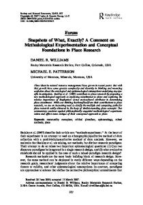
serve as communication media function, such as MANET and other commercial products for ad hoc communication. Fig. 2 shows a more detailed system level structure, which is used by our project. Network and virtual machine technology are used to support the whole simulation system. This structure is mainly for the purpose of easy expand. In one workstation/PC, one or more UAV can be simulated. And if necessary, more workstations/PCs can be added easily to provide more powerful computation resource. The virtual machines and Unity3D server/client also can be setup in different workstations/PCs, because all the communication system between them is based on network. Hence the developed simulator system is scalable. Users can setup their own structure based on their requirements. In the follows, we will give brief introductions to each portion of ROSUnitySim. Network Server Windows Virtual Machine Ubuntu
Unity3D Server Engineering View
Communication Server
UAV Unity3D ROS Client
…
UAV Unity3D … ROS Client
GCS
Clients Windows Virtual Machine Ubuntu ROS
Port
Unity3D Client Sim Environment
UAV Dynamic Model & Controller High Level Algorithm Communicator
Unity3D Server
UAV Status
Sensor Model
Unity Socket
Port
Virtual Machine
Unity3D Client
Virtual Machine
UAV Unity3D ROS Client
Unity3D Client ... ...
… Windows Windows ... ...
Communication Server (stand alone in Linux)
Figure 2. System Level Structure GCS
Figure 1. Structure of ROSUnitySim
In Fig. 1, the main structure of ROSUnitySim is presented. As seen from the figure, a game development structure, server and client mode has been adopted. By using this kind of game mode, our simulator can easily handle multiple UAVs if CPU of workstation is power enough. For each UAV, it has a ROS section and a Unity3D section. The Unity3D server and clients will serve as sensing environments as real cases. Communication server section will Prepared using sagej.cls
2.1 Unity3D Section
Unity3D is a game development ecosystem: a powerful rendering engine fully integrated with a complete set of intuitive tools and rapid workflows to create interactive 3D and 2D content; easy multi-platform publishing; thousands of quality, ready-made assets in the Asset Store and a knowledge-sharing community 19 . Unity3D allows game developers to create games that delight players on any platform. The high fidelity model, live environment and capability to be adapted
4
Journal Title XX(X)
to any platform which can be achieved by Unity3D make it the best choice of our 3D highfidelity simulator. Moreover, natural environment and weather conditions can be simulated in the Unity3D, too, to monitor the possible complex outdoor influence on UAV in physical test through simulations. Though, it may still be far away from the actual light, but we can continue employ the potential of the Unity3D in environment simulation. Another crucial advantage of the Unity3D compared to our existing simulator is that the collision regions of objects can be as narrow and detailed as the shape of the objects themselves. 2.1.1
3D Environment Modeling In order to
improve the confidence level of the simulation system, 3D virtual environments need to be modeled as real as possible. There are two parts need to be considered to model the objects in the simulator. The first one is mesh, which determines the visual shape of the object. The more meshes are used, the more accurate the object is. But more meshes need more compute resource to render. So the balance should be considered based on the requirements. For visualization purpose, the corresponding textures will be added to the surface of the mesh. Fig. 3(a) shows the tree’s meshes(blue parts) and rendered results with the textures in Unity3D. The other one is collider, which is used for raycasting, collision detection and other physic simulations. Just like mesh, how much detailed collider should be modeled depends on requirement. Reducing detail level of the mesh or the collider may be an alternative choice if the Unity3D takes too much compute resource. In the case of UAV model as shown in Fig. 3(b), which we developed for simulation purpose, components like propeller, body frames and motor are implemented. This model can be easily adapted into the test of physical control if required. In Fig. 4, one UAV is flying autonomously in our developed 3D virtual urban environment. In the figure, we can also see camera view of the UAV and 2D sketched map on the left and right bottom of the figure, respectively. 2.1.2
(a) Modeling of tree
UAV Sensor Modeling All hardware sen-
sors mounted in our UAVs are modeled in the simulator, including laser scanner, camera and so on. LIDAR Prepared using sagej.cls
(b) UAV 3D physical model
Figure 3. Tree and UAV modeling
Figure 4. UAV flies in city
The LIDAR sensor used in our UAV system is Hokuyo UTM-30LX. The main features modeled in the simulator are: (1) Detectable range is .1m30m (2) Scanning angle 270 degrees (3) Scan speed 25ms (4) Compact Size: W60xD60xH87mm (5) Small weight, 370g. There are two LIDAR sensors mounted on our UAV platform. One of them is placed static on the top of the platform. The main purpose of this LIDAR sensor is used by SLAM to estimate the location of the UAVs. Another LIDAR sensor is mounted on the front part
Smith and Wittkopf
5
(a) LIDAR sensor in operating
Horizontal Lidar Sensor
Nodding Lidar Sensor
(b) Real LIDAR sensor
Figure 5. LIDAR sensor
of the UAV platform. Specially, this LIDAR sensor is keep tilting (nodding up and down) according to a certain speed to obtain 3D obstacle information. These two LIDAR sensors’ sensing data is quite important, since these data will be used for localization and mapping, and also for 3D path planning. As seen from Fig. 5(a), two LIDAR sensors of one UAV are operating simultaneously in a forest environment, where red color representing nodding LIDAR and blue color representing horizontal static LIDAR. For the comparison purpose, placement of two LIDAR sensors mounted on our real UAV platform is shown in Fig. 5(b). According to LIDAR sensor’s specification, there are total 1081 data for each 270 degrees scan. The scanning frequency is around 40 Hz. In Unity3D, one straightforward technique is to use Physics.Raycast scripting API to develop customized LIDAR sensor model. In our Raycast script, scanning range and angle are calculated based on UAV’s state. Both LIDAR sensors developed can be run simultaneously. Usually, for the Raycast in Unity3D, it runs in the main thread. When we run several UAVs in the same workstation, Raycast calculation for each UAV can be done in different instances. According to our experience, if the simulated 3D map is Prepared using sagej.cls
quite complex, then the Raycast will take almost all CPU resource. In our development, we have implemented some novel idea, for example, for Raycast, the calculation will only consider the environment information near each UAV and the detail level of collider may be reduced to speed up the calculation. To let LIDAR sensing as real as possible, in Unity3D, we can set the sampling frequency to a fixed value, for example, 40 Hz, even though sometimes workstation can support higher frame rates. For the measurement error, we can add some noises into scan data to simulate the real laser’s data. Also collider detail level should be considered. Camera The camera sensor development is easy in the most of game engines. In our system, one camera is mounted static on the front of the UAV platform. The camera model is from the original camera of Unity3D. Field of View (FOV) is 60 degrees, and perspective projection is used. The main purpose of the camera is target detection. Fig. 6 shows the rendering of a camera. To speed up the processing, only the objects near the camera will be rendered, so output of a camera just includes these rendered objects. Any objects out of range will be ignored.
Figure 6. Camera Render
Figure 7. Fast Rendering
6 2.1.3
Journal Title XX(X) Fast Rendering For real-time simulation
tests, rendering speed is a very important requirement, which determines if the whole system can touch the frequency of the real system. To increase the rendering speed, some modifications are required to be applied. For example, if the performance of laser based algorithms need to be tested, then the unrelated elements can be removed, such as textures, small detailed objects, lights, shadows and so on. Fig. 7 shows one example where all leaves and textures are not rendered, and the objects out of the laser range are also removed. Avoiding to rending unnecessary objects can boost performance of the rendering speed, which can save the CPU resource efficiently. If the camera based algorithms need to be tested, the textures should be remained, but the level of details can be reduced where objects are far from the camera.
to select. The number of UAVs should be set for initialization. In client interface, as shown in Fig. 8(b), ROS data and image port should be set for communication between the Unity3D and the ROS, and the parameter of IP address and port is point to server. After connection being established, the whole simulation will be running. During the actual simulations, the server and the client both allow three kinds of user views, walkthrough, flythrough and UAV. Users can control the view position for the walkthrough and the flythrough modes to monitor the moving speed and trajectory of the UAV from macro perspective. As stated on the left top corner of Fig. 4, it illustrates how the walkthrough view looks like. The walkthrough view is similar to people walking so that it will be blocked by objects, while the flythrough mode will not be influenced by the simulated environments. The UAV view is from the back of the activated UAV and follows the movements of the UAV. Users cannot adjust the view angle and position for the UAV view. It is appropriate view to investigate the movements of the UAV more specifically in terms of stableness and smoothness. Furthermore, as shown on the right bottom of Fig. 4, the server has a global map which allows users to investigate the global position of the UAV as indicated by the red circle in the map. 2.2 ROS Section
(a) Server
(b) Client
Figure 8. Server and Client Configuration Interfaces
2.1.4
User Interface Fig. 8(a) shows the server
configuration interface of the Unity3D simulations. There are some environment types for users Prepared using sagej.cls
ROS is an open source operating system for robots, which is originally developed in 2007 at the Stanford Artificial Intelligence Laboratory 14 . The modular architecture and easily syncing threads make ROS flexible and convenient. Same nodes can be multiply used for different operations. For developing convenience and easy to setup, we choose the ROS as a high level algorithm developing and running environment. For the hardware side, the on-board x86 computer MasterMind is powered by the ROS/Ubuntu. While in the simulation environments, MasterMind is replaced by a virtual machine, which can create an isolated environment in workstations to run the ROS/Ubuntu. Except some hardware drivers, this virtual environment can be considered the same as that in the real hardware. In the ROS section of ROSUnitySim, we can build all the algorithms which will be implemented
Smith and Wittkopf
in CPU sections of the UAVs, i.e., MasterMind and Gumstix, etc.. For our case, we develop ROS nodes, e.g., SLAM, path planning, Octomap conversion, UAV dynamic model, Control logic, and Communicator, etc. Here we give a brief introduction to several nodes which play important roles in our simulation system. 2.2.1 Simulated UAV Dynamic Model and Control In order to simulate UAV control sections,
including inner loop and outer loop control laws, we have used our identified quadrotor model, including Roll/Pitch dynamics, Yaw dynamics, and Heave dynamics. For the outer loop control, we have implemented Robust and Perfect Tracking (RPT) control law 20 . We have put all control parts together to serve as simulated UAV dynamic model and control. The output of this node is UAV’s reference pose. Actually, in the most game engine based simulators, the UAV dynamic model is not provided by their physic engines. If users want to use these simulators, they have to build up their own UAV model for simulations. Unity3D does not have aerodynamic physic engine either. For consideration of easy modification and extension, the UAV dynamic model is executed in the ROS with controller as a single node. 2.2.2
Control Logic Control logic node is an
important part especially when UAVs are handling complex tasks. In our case study, it will mainly serve as task manager, i.e., global planning, multiUAV collision avoidance, information sharing, etc.. 2.2.3
Communicator When Control logic node
wants to share information with other UAVs, the communicator is the only path. In the simulations, it will connect to communication server, which is like a virtual router simulated by software, to exchange data with other UAVs’ communicators. More detailed technique will be discussed below. In real hardware environments, the communicator and communication server will be replaced by MANET or other similar products. 2.2.4
7
the coordinates to the ROS standard frame with x forward, y left and z up. The node of the UAV dynamic model and control is responsible for generating the pose of the UAV and sending it to Unity client via the Unity socket node. Hence the Unity socket can be seen as a bridge between the ROS and the Unity3D. A customized driver, which connected to Gumstix or Pixhawk will take its place when the system works in a real hardware environment. Additionally, to ensure the data transferred correct, checksum technique is achieved. 2.3 Communication Section 2.3.1 Communication Protocol The purpose of
the communication protocol is to allow communication among UAVs and ground control station using a variation of the TCP/IP communication protocol implemented in both C and C++. At any time, any station can begin transmission of data to any other stations, whereby the data being transmitted will in one of two pre-defined formats: command data format and sensing information format. The communication server module is stand alone in Linux system to connect with ROS. The basic structure of the developed communication module is presented in Fig. 9. As seen from Fig. 9, in the ROS section, each UAV has a communication node to send and receive information from GCS, and other UAVs. To simulate real world case, this brings us to addition of the “Communication Server” module, which acts as a router, which all the stations are connected to. The main functionality provided by this module is to be able to receive a data packets from any source station, and retransmit the data packets to the intended destination station. UAV Batch1 (ROS)
GCS (ROS)
Independent Routing Server (C Application)
UAV Batch2 (ROS)
Unity Socket Unity socket node, which
connects to Unity client via TCP/IP, mainly focuses on data exchange between the ROS and the Unity3D. All the sensor data, such as laser, IMU and sonar, generated by the Unity3D is sent to Unity socket, and then Unity socket will transform Prepared using sagej.cls
UAV Batch N (ROS)
Figure 9. Basic structure of communication module
8
Journal Title XX(X)
2.3.2
Communication Server Module Hand-
shake Protocol When any station attempts to connect with the Communication Server, the server expects to receive an “identifier” packet containing the station’s unique ID, before it allowing the socket to remain open for further communications. The unique ID is in the format of a character array of size 2, because it requires 2 separate variables to identify its batch and plane numbers. However, it is not practical to store the ID based on the data format of a 2-dimensional array, which is why we use a basic hash algorithm: liner identity = 4 × (batch num) + plane num (1) to reduce the 2D arrays, based on their maximum values, to a corresponding linear identity. Finally, we will need to store an internal mapping of which socket is open with which station. As such, we store the socket identifier for the open connection together in an array, by setting the hashed (linear) identity of the station as the array index. 2.3.3
Multi-thread Programming The connec-
tion (socket) between the server and each station should hold equal priority. As such, to ensure fairness, we allocate each connection to a single thread in the process, and schedule each thread using the round-robin scheduling protocol. 2.3.4
Preventing Socket Clash While the re-
transmission of data follows the “store and forward” principle, where the server stores individual packets until the entire message is received before forwarding it to the destination, the data itself is not actually backed-up on the server. As such, a failure scenario would be if two or more stations try to transmit a message to the same destination within a short time span. The solution we have implemented to prevent this issue is to use MUTEX to lock the transmission process within each individual socket. Now, we do not lock the entire transmission function itself, because this is not optimal as forces the system to only be able to transmit to one station at a time. For example, consider the scenario that within a short time span, these 2 transmissions are attempted: • Station 1 transmits to Station 3 (slightly sooner than below) • Station 2 transmits to Station 4 (slightly later than above) Prepared using sagej.cls
In this case, if we have a single MUTEX on the transmit function, then Station 1 will lock the MUTEX before it transmits to Station 3. Then, when Station 2 attempts to lock the MUTEX before it transmits to Station 4, it will be blocked because the MUTEX has already been locked by Station 1. This is not ideal because it will not cause problems if there are simultaneous ongoing transmissions to different destinations. Instead, what we do is to declare multiple MUTEX variables that can be locked, and each Station has its own dedicated MUTEX. This way, only when there is an ongoing transmission to a specific station, will its corresponding MUTEX be locked. 3 Key Technical Issues 3.1 Client/Server Structure based on Unity3D
During development of the simulator, we found that the Raycast API of Unity3D engine only can be used in main thread, which means if all the UAVs’ laser data is generated in one Unity3D instance, just one CPU core can be used to handle the process of data generation. Because the Raycast API of the Unity3D is inefficient, this traditional structure will cause the simulation running slowly. In addition, the computation resource of other CPU cores is also not fully used. To overcome these issues, we found two potential solutions. One is the technology of Compute Shaders in the Unity3D, which uses GPU to handle the computing tasks. In this solution, each raycast will be parallel computed in different cores of GPU, so it can reduce the total time of processing all 1081 laser ray lines. However, to use this technology, we must transfer the environment information from CPU memory to GPU memory and then send the results from GPU memory to CPU memory, which is very slow and will take about 20ms. There is not enough time to process other things such as raycasting itself, because we want the frequency to touch 40Hz. Moreover, when multiple UAVs are added to the simulator, the situation will be worse. Because Unity3D limits multiple threads, all APIs including Compute Shaders must be called in the main thread and it can use only one CPU core’s resource, the simulation will be slow in a multiple UAVs environment. The other solution is using a Client/Server structure, just like network games. In this structure,
Smith and Wittkopf
the main task of the server is information receiving, storage and distribution via network, so every client can share its UAV state to other clients through the server. The server is also responsible for rendering the environment and showing the state of UAVs. For the client part, just one UAV is handled in one client instance, so it only processes two lasers’ data and one CPU core’s resource is sufficient for computing raycasting in 40Hz by using Unity3D built-in APIs. To further improve the performance, the client part is not rendered as detailed as the server, it just remains the basic environment information. For example, textures, light and shadow are removed in client, and colliders are kept for raycasting computation. This multiple instance structure fully uses CPU resource, and it’s also very easy to extend two or more workstations to support more UAVs’ simulation, because all the communication functions are based on network instead of local memory. Due to these advantages, we chose the second solution, and it can handle as more as three UAVs in a workstation with 6 CPU cores. 3.2
Interface Between ROS and Unity3D
As described above, the whole environment part of the simulation is implemented in the Unity3D, which can be separated to the client and the server. For controlling the UAVs, ROS is chosen to process the high level algorithms to control the UAVs’ behavior such as SLAM, path planning, task manage and so on. So ROS needs to receive sensor information from the Unity3D part and sends the states of UAVs to the Unity3D. For this communication structure, the client part of the Unity3D is considered as the server, and ROS part is the client. The exchange of data packets are achieved by TCP/IP protocol. To make sure the data transferred correct, a checksum algorithm CRC16 is used to verify every package of data. This interface between the ROS and the Unity3D has been developed which can support multiple UAVs applications. The ROS node, Unitysocket will communicate to the preset IP address which should be the address of the Unity3D server. For every spin, the ROS client receives laser scan data (1081 data array for 270 degrees, the same as real 30m URG laser scanner) and publishes it as LaserScan message onto the topic “laser/horizontal/scan”. Prepared using sagej.cls
9
It also publishes the transformation required by the ROS based on the state of Unity3D UAV model. This node computes the transformation of vertical laser scanner based on the x, y and z rotation of Unity3D laser model. With the help of TCP/IP protocol, wireless communication between different Unity3D servers and clients is possible. Originally a local interface which allows Unity3D and c++ control logic to assess same memory for data exchange was implemented. However, this interface can only be used in Windows platform, which means it can’t communicate with ROS that usually runs in Ubuntu. Using network protocol instead, not only solve this issue, but also realize communication between remote server and client. Currently, we have managed to develop an ROS/Unity3D interface, which can support multi-UAV data transmissions. Additionally, for images captured from simulator’s camera transmitting, another channel is created, which means the camera data processing is standalone. The Unity client listens to a special port, and when a image receiver connect to it from ROS, it will send images at certain frequency. We know that image transmission and processing is a high load task, so this design separates image task from other tasks. 3.3 Distributed Computation
Thanks to the network based client/server structure, the whole simulation task can be separated to several subtasks. These subtasks can be assigned to any PCs or workstations as long as they are in the same network. For Unity3D part, the server and each client are designed as standalone instances, so they can be setup either in several common PCs or a powerful workstation. And in ROS, every node also can be put in different computers, which is more flexible. It’s useful when simulating multiple UAVs. From the results of our experiment, a six cores workstation can only handle three UAVs. If we want to process more UAVs at the same time, more PCs or workstations can be added easily without any software modification. Furthermore, in most situations, three common dual-core PCs have more powerful parallel computation ability than six-core workstation, but their total price is cheaper than workstations’. So for economy consideration, the distributed computation supporting
10
Journal Title XX(X)
provides more choices for simulating multiple UAVs. 4
Performance Analysis
4.1
CPU Usage
Figs 10 and 11 show the performance of each Unity3D instance, when the FPS is not limited. We can see the CPU proceeding time of each frame of both the Unity3D server and client is below 16ms, which means that the sensors’ data generation speed can be as fast as 60Hz, or even more.
Figure 10. Unity3D Server CPU Usage
Table 2. One UAV in Workstation #1
Figure 11. Unity3D Client CPU Usage
To reduce the CPU usage, the FPS in the Unity3D is limited to 40Hz, which meets the frequency of simulated laser scan. In a workstation, one server and three clients are executed, the graphics configure of each instance are 640x480, the fastest speed. In idle condition (not start ROS part), the CPU usage of server is 2%, and that of each client is 7%. Then start ROS part, each ROS instance takes about 20% CPU usage, while the Unity3D’s CPU usage keep the same. The whole CPU usage is about 85%. So our simulation system can support three UAVs real time simulation in one workstation. 4.1.1 Performance for Multiple Simultaneous UAVs and Computers To test the performance for
multiple UAVs and computers, two workstations are set up as shown in Table. 1. Three virtual Table 1. Configuration of Workstations
# CPU type Freq. #1 E5-2630 v2 2.6GHz #2 E5-2630 v3 2.4GHz
Cores 6 8
Cache 15M 20M
machines are created in each workstation. The configuration of each virtual machine is 3 cores Prepared using sagej.cls
and 3GB memory. We use Windows built-in program called Performance Monitor to log the CPU usage. The duration of each test is 60 seconds. First we start Unity server, and then add the first, the second and the third UAV into the simulator in the workstation #1. Finally, another three UAVs in workstation #2 are added into the simulator. From Tables. 2, 3 and 4, we can see that the more UAVs, the more CPU usage needed by each instance. That’s because every time a UAV is added into the simulator, the communication module in each instance has to handle one more UAVs’ data. Tables. 4 and 5 show the performance of simulating 6 UAVs in 2 workstations. It’s obvious that workstation #2 has lower CPU usage, because of its more powerful CPU. Note that the load of each virtual machine is based on the complexity of the high level algorithm program, so it will not be the same for different tasks and algorithms. While for Unity server and clients, the performance will not be largely different in different situations.
Program Unity-Server Unity-Client #1 Virtual Machine #1
CPU Usage(%) 1.4 2.6 13.3
Remark Server UAV #1 UAV #1
Table 3. Two UAVs in Workstation #1
Program Unity-Server Unity-Client #1 Unity-Client #2 Virtual Machine #1 Virtual Machine #2
CPU Usage(%) 2.3 3.1 3.2 13.5 12.5
Remark Server UAV #1 UAV #2 UAV #1 UAV #2
Table 4. Three UAVs in Workstation #1
Program Unity-Server Unity-Client #1 Unity-Client #2 Unity-Client #3 Virtual Machine #1 Virtual Machine #2 Virtual Machine #3
CPU Usage(%) 2.6 3.7 3.8 3.6 13.0 12.5 12.4
Remark Server UAV #1 UAV #2 UAV #3 UAV #1 UAV #2 UAV #3
Smith and Wittkopf
11
Table 5. Three UAVs in Workstation #2
Program Unity-Client #1 Unity-Client #2 Unity-Client #3 Virtual Machine #1 Virtual Machine #2 Virtual Machine #3
CPU Usage(%) 2.1 2.2 2.1 8.5 8.1 8.2
Simulation System Unity3D
Remark UAV #1 UAV #2 UAV #3 UAV #1 UAV #2 UAV #3
Real System Ranger Driver High Level Algorithm Height
Laser Driver
Scan
IMU
SLAM
3D Mapping
Pose
Map
3D Path Planning
Filtered Ref
Path
Task Manager
4.2 Different Proceeding between Simulation and Real System
Keeping the algorithm code the same between simulation and real system is important for testing, which can reduce the error caused by modified codes and increase the simulation system’s reality. The code of high level algorithm running in our simulation system can be easily moved to real system without any modification. The different proceeding paths between the simulation and the real system are shown in Fig. 12. Black part is for high level algorithms, which is the public part of both simulation and real systems. Actually it is the interested part that needs to be tested in the simulation and the real environments. As the special part of the real system, ranger driver, laser driver and FCU (Flight Control Unit) get height, scan and IMU data from real sensors and then send to the high level algorithms. Additionally, FCU receives current UAV pose and reference waypoints from the high level algorithms and controls UAV’s pose based on them. For the simulation system, sensor data is generated by the Unity3D, which simulates the environment state and gets UAV’s state from its dynamic model. Simulator has its own controller to replace the FCU’s function. Like FCU, the dynamic model and controller collect UAV’s current pose and reference waypoints, and generate UAV’s state. In both the real system and the simulation system, the high level systems are the same, only some data links are changed. Thanks to the ROS communication structure, this modification is quite small, only some topics’ names need to be changed. In the simulator, different launch files are created to set these topics’ names, for different purposes, such as simulation, flight test, ground test and so on. For different cases, just use related launch file and no need to modify its source codes. This feature is very useful in real projects. Prepared using sagej.cls
Reference
FCU
Dynamic Model & Controller
State
Figure 12. Simulation and Real System
5 From Simulator to Real Flight Test
Here, we provide a demonstration example using our developed simulator. One UAV is supposed to search the forest autonomously without GPS information. Based on onboard two LIDAR sensor, UAV needs to run SLAM algorithm to work out its relative location information. In addition, 3D path planning algorithm is run for UAV navigation and guidance.
Figure 13. Unity3D view of forest search
Figure 14. ROS view of forest search
By solving the technical issues in Unity3D and developing UAV model and control algorithms in
12
Journal Title XX(X)
ROS, our hybrid simulation system can be used to test and verify various UAV navigation and guidance methods in cluttered environments. 5.1
Simulator Demonstration
For our forest search application, the main purpose of flight test is to verify that whether ROS and Unity3D can work together smoothly. Important issues include sensor data sampling frequency, communication latency between ROS and Unity3D, etc. The workstation we used for our simulation system is a six-core, E5-2630v2 processors. The graphic card of this PC is GTX 780 Ti. Currently, according to our test, this workstation can handle 3 UAVs simultaneously running 40 Hz LIDAR sensing in a complex 500 m × 500 m forest map developed in Unity3D. In Figs 13 and 14, UAV views in Unity3D and ROS are shown respectively. In the ROS view in Fig. 14, we can also see 3 UAVs’ local path planning and also reconstructed 3D octomap. In Fig. 13, we can see that 3 UAVs are running simultaneously in the same workstation. In some case, for multi-agent system, we need to test the cooperative control logic. Hence, how many UAVs can run in the same workstation is an important evaluation factor for the developed simulator. The simulation demonstration videos can be watched and downloaded from the following Youtube links: https://youtu.be/CIrKFFXL5Xk, https://youtu.be/06UFkBluICo. 5.2
Flight Test
× 60 m near to our campus. The tree density there is sparser than that in our simulation 3D environments. Finally, we also succeed in the flight test. In the near future, we will conduct multi-UAV cooperative forest search flight test in a 500 m × 500 m forest area. The flight test demonstration video can be watched and downloaded from the following Youtube link: https://youtu.be/rLggamUHuf4. 5.3 Analysis of the Real and Simulation Flight Tests
To compare the real and simulator flight data, real and simulation experiments have been conducted in the same area of the forest. Fig. 16 shows the appearance of the forest in Unity3D, and Fig. 17 provides a more clear view of trees’ position. Figs. 18, 19 and 20 present the results of this experiment. In the experiment, UAV started from zero point, flied clockwise, and returned to the original point. From these figures we can see that the UAV’s moving trajectories and reconstructed maps in the real flight and the simulator are close enough which indicating that the system has the ability of simulating a real-time UAV flight. Some interesting findings: Because of the unavoidable differences between dynamic model and real UAV/environment, the dynamic behavior of simulating flight has a certain difference from that of real flight, which can be observed in Figs. 19 and 20. One interesting finding is that in the simulator environment, the UAV completes the task faster and slightly smoother than that in the real flight. One of the reasons is that the simulator environment is ‘cleaner’. Due to the limited memory in our workstation, it is not possible to model the leaves of the trees, and other obstacles in much details.
Figure 15. Flight test in a foliage environment
Currently, after successful tests in ROSUnity3D, we have finished flight test for single UAV in real foliage environment. The test scenario is shown in Fig. 15. The test field is around 60 m Prepared using sagej.cls
Figure 16. Trees in the simulator environment
Smith and Wittkopf
13 Y Direction
30
sim real
25
Position (m)
20
Figure 17. Simulated tree trunk
15 10 5
real measured obstacles sim measured obstacles real trajectory sim trajectory
Trajectory and Map 50
40
0 −5 −50
0
50
100 150 Time (s)
200
250
300
30 X Axis (m)
Figure 20. Y Axis Performance 20
10
cost occurs. It should be useful in the academic arena.
0
−10
7 Conclusion and Future Work −20 50
40
30
20 10 Y Axis (m)
0
−10
−20
Figure 18. Real and Sim Trajectory and Map X Direction 35 sim real
30
Position (m)
25 20 15 10 5 0 −5 −50
In this paper, we gave a brief introduction to our newly developed ROS/Unity3D hybrid UAV simulation system. By developing the sensor modeling, especially LIDAR sensor, interface between ROS and Unity3D, we have managed to make the simulation system run smoothly when there exists more than one UAV. Since the simulation structure is almost the same with real system, the developed simulator is quite useful for real UAV application tests, especially for multiUAV applications. In the near future, we will release the whole system to public for research development. Acknowledgements
0
50
100 150 Time (s)
200
250
300
The authors would like to thank Veldis Experience Pte Ltd for helping us build 3D urban and forest maps.
Figure 19. X Axis Performance
References 6
Impact
ROSUnitySim has the capacity to help UAV researchers to evaluate their developed algorithms, UAV models, inner loop control, control logic, etc. The researchers can always challenge their developed method in extreme conditions. For example, in Unity3D, a challenging environment can be built in high-fidelity. Another important issue is that both ROS and Unity3D are free softwares. Hence no additional Prepared using sagej.cls
1. Cai G, Chen B, Lee T et al. Design and implementation of a hardware-in-the-loop simulation system for small-scale UAV helicopters. Mechatronics 2009; 19(7): 1057–1066. 2. Bortoff SA. The university of toronto rc helicopter: a test bed for nonlinear control. In Control Applications, 1999. Proceedings of the 1999 IEEE International Conference on, volume 1. pp. 333–338. 3. Dittrich JS and Johnson EN. Multi-sensor navigation system for an autonomous helicopter. In Digital Avionics Systems Conference, 2002. Proceedings. The 21st, volume 2. pp. 8C1– 1. 4. Gavrilets V, Shterenberg A, Dahleh M et al. Avionics system for a small unmanned helicopter performing aggressive
14
5.
6.
7.
8.
9. 10.
11.
12.
13.
14. 15.
16.
17.
18.
19. 20.
Journal Title XX(X) maneuvers. In Digital Avionics Systems Conference, 2000. Proceedings. DASC. The 19th, volume 1. pp. 1E2–1. Cai G, Chen BM, Peng K et al. Modeling and control of the yaw channel of a UAV helicopter. IEEE Transactions on Industrial Electronics 2008; 55(9): 3426–3434. Zhang X, Xian B, Zhao B et al. Autonomous flight control of a nano quadrotor helicopter in a GPS-denied environment using on-board vision. IEEE Transactions on Industrial Electronics 2015; 62(10): 6392–6403. Cicirelli F, Furfaro A and Nigro L. An agent infrastructure over HLA for distributed simulation of reconfigurable systems and its application to UAV coordination. Simulation 2009; 85(1): 17–32. Javaid A, Sun W and Alam M. Uavnet simulation in uavsim: A performance evaluation and enhancement. In Testbeds and Research Infrastructure: Development of Networks and Communities. Springer, 2014. pp. 107–115. Opensim. Http://opensimulator.sourceforge.net/. Freese M, Singh S, Ozaki F et al. Virtual robot experimentation platform v-rep: a versatile 3D robot simulator. In Simulation, Modeling, and Programming for Autonomous Robots. 2010. pp. 51–62. McDowell P, Darken R, Sullivan J et al. Delta3D: a complete open source game and simulation engine for building military training systems. The Journal of Defense Modeling and Simulation: Applications, Methodology, Technology 2006; 3(3): 143–154. Lewis M, Wang J and Hughes S. USARSim: Simulation for the study of human-robot interaction. Journal of Cognitive Engineering and Decision Making 2007; 1(1): 98–120. Koenig N and Howard A. Design and use paradigms for gazebo, an open-source multi-robot simulator. In IEEE/RSJ International Conference on Intelligent Robots and Systems(IROS 2004), volume 3. pp. 2149–2154. Robot operating system. Http://wiki.ros.org. Liao H and Qu Z. Virtual experiment system for electrician training based on Kinect and Unity3D. In Mechatronic Sciences, Electric Engineering and Computer (MEC), Proceedings 2013 International Conference on. pp. 2659–2662. Wang S, Mao Z, Zeng C et al. A new method of virtual reality based on Unity3D. In 2010 18th International Conference on Geoinformatics. pp. 1–5. Falcone A, Garro A, Longo F et al. Simulation exploration experience: A communication system and a 3D real time visualization for a moon base simulated scenario. In Distributed Simulation and Real Time Applications (DS-RT), 2014 IEEE/ACM 18th International Symposium on. pp. 113– 120. Meng W, Hu Y, Lin J et al. ROS+unity: An efficient highfidelity 3d multi-uav navigation and control simulator in gpsdenied environments. In Industrial Electronics Society, IECON 2015-41st Annual Conference of the IEEE. pp. 002562– 002567. Unity3d. Http://unity3d.com. Cui JQ, Lai S, Dong X et al. Autonomous navigation of uav in foliage environment. Journal of Intelligent & Robotic Systems 2015; : 1–18.
Prepared using sagej.cls